In this article:
- Nuances of designing water supply networks
- JV requirements for the design of water supply and sewerage networks
- Types of water supply networks
- Stages of designing water supply networks
- The importance of developing a water supply network project by professionals
Designing water supply networks is a complex process that must be entrusted to professionals. Depending on the purpose of the building, at the design stage, water consumption standards, the type of pipes and equipment used, the design capacity and much more are calculated.
What will be included in the final documentation is influenced by various factors: the type of water intake, the height and purpose of the structure, distance from the source, etc. In our article we will tell you what the design of water supply networks consists of, what stages this process is divided into and why it is necessary to select quality performers.
Water distribution unit in the apartment.
After the water metering unit, it is necessary to correctly distribute water to all consumers: sink, bathtub, toilet, washing machine, dishwasher, water filter, refrigerator with water or ice supply, these are the most common appliances used in apartments. So, in order for water to reach all devices, it is necessary to install a distribution unit, which is otherwise called a collector. Typically, a given collector should have exactly as many connections as you have appliances that consume water, but it happens that there may be several appliances per connection, which can lead to some inconvenience. This connection of devices is called serial.
Design of water supply and sewerage
engaged in the design of engineering systems. One of the priority areas of our work is the development of projects for water supply and sewerage systems.
Individual water supply and sewerage in a house, apartment, office, restaurant... this is an opportunity to organize an engineering system that will work properly in any conditions. Our design is a high-quality and competently compiled package of documents that will easily allow you to quickly install the system.
Example of a water supply and sewerage project for a house
Back
Forward
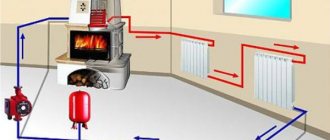
Water supply scheme for a private house
The water supply of country private houses consists of several elements. First of all, it is a source of water. And:
- pump for supplying water from the source to the consumer;
- a hydraulic accumulator, which creates a certain pressure in the system;
- cleaning filter system;
- installation of water heating equipment;
- collector system.
Central water supply or your own well?
It is no secret that home owners in provincial villages very often face the problem of lack of centralized water supply. And in those places where it exists, the water quality is not always satisfactory.
There is only one way out - drilling a well.
Well for water
If a well has to be drilled in an already constructed building, then all possible nuances for its operation should be taken into account. It is best to place the well in a technical room free of foreign objects. After all, this engineering structure will require periodic maintenance. It takes up quite a lot of space and needs good protection from adverse weather conditions.
Axonometric diagrams of sanitary systems
To perform axonometric diagrams of plumbing systems of buildings and structures, frontal isometry with a left-handed axis system is used. This makes it possible to use undistorted measurements on all axes. To designate axonometric diagrams of cold and hot water supply networks, system marks are used, placed directly above the diagrams. The full names of the systems (for example, “System diagrams B2, T3”) are indicated in the relevant specifications.
The figures below show axonometric diagrams of the hot (T3) and cold (B1) water supply pipeline systems of the building. The schematic representation of the water supply system shows shut-off valves, pipe diameters, branches to the risers, places where water drains, as well as pipes for moving from one pipe diameter to another. The level of the first floor is marked using a horizontal line near the risers. In addition, the B1 water supply diagram contains a designation that to arrange its input, pipes with a diameter of 50 millimeters should be used, and the elements should be connected using sockets.
Axonometric diagram of water supply pipelines
Axonometric diagram of hot water supply pipelines
Residential building plan
Drawing of a residential building plan with inputs and outputs
The image shows a plan of a residential building that includes outlets of the sewer system, inputs of the heating system, cold and hot water supply with their reference to the angular coordination axes. In addition, it shows the diameters of the outlet and inlet pipelines, and also shows the sewerage wells KK-1, KK-2 and KK-3. According to current codes and standards, the plans must indicate pipe diameters, required elevations and dimensions of sloped pipes, sewer wells and network profiles.
Residential basement plan
The fragment below of the basement plan of a residential building includes an image of the sewer (K1) and water supply (B1) systems. The place where the water supply is introduced into the building is indicated, as well as where the sewage system is discharged into the sewer well (KK-1). In addition, the plan shows the sewer risers (StK1-1…StK1-3) and water supply (StV1-1…StV1-3). On the part of the water pipeline that is located in the water metering unit, a control valve (Ø 15), a water meter (Ø 40) and a pair of valves are mounted. On the water supply line coming from the B1-3 riser, there are outlets that follow the hand pump of the heating system, the sink and the watering tap. In addition, on the part of the sewer pipeline going to the outlet, the diameters of the pipes, cleaning locations, slopes and lengths of straight sections of the pipeline are indicated.
Fragment of the basement plan of a residential building
Recycling water supply system
This scheme is not in demand in household construction, but is very useful, for example, at a car wash. Due to repeated use, significant savings in valuable resources are achieved.
A mandatory element of such complexes is the equipment of settling tanks and filters. The benefits include reduced consumption and wastewater, which has a negative impact on the environment. In large industries, steam can be used as a source. This results in large volumes of distilled water needed in many production processes.
Ground floor plan
This plan shows the risers of sanitary units located in the grooves of the main walls: water supply (StV1-1...StV1-3), sewer (StK1-1...StK1-3) and hot water supply (StV1-1...StV1-3). The diameters of these pipeline systems are also indicated.
Fragment of the ground floor plan
The designed pipeline networks, which are plotted on the plans, are the basis on which axonometric diagrams of plumbing systems are made. These diagrams provide a clearer picture of how the various elements of a building's piping systems are positioned in relation to each other.
Selection of materials
Pipes made of copper, metal-plastic, and polypropylene are popular for internal water supply.
A water supply and sewerage project includes the selection of pipelines with the required parameters. The industry produces a wide range of pipes for drinking water and waste liquids.
Pipeline materials:
- metal-plastic,
- cast iron,
- steel,
- copper,
- polyethylene,
- polypropylene,
- polyvinyl chloride,
- fiberglass,
- asbestos,
- reinforced concrete.
The most common products are made of polymers, metal-plastic, and stainless steel. Internal water pipes are made of PPRC polypropylene, metal-plastic, PEX cross-linked polyethylene, corrugated stainless steel. Internal drain pipes are made from PP polypropylene, gray PVC and HDPE high density polyethylene.
For external water supply systems, products made of PE polyethylene and polyethylene with a PE-RC protective layer are used. External drainage systems are made of orange polyvinyl chloride, corrugated polyethylene and corrugated two-layer PP polypropylene.
The designer decides on the type of pipe, based on the technical specifications of the project, the advantages and disadvantages of the material, and also takes into account the wishes of the customer.
Ventilation system equipment
In order to comply with sanitary standards and make living in the house as comfortable as possible, the sewage system must be equipped with ventilation.
To prevent stagnation of gases in pipes and their penetration into living quarters, a vent pipe is installed.
A fan pipe is a simple vertical structure that resembles a riser in appearance. It is placed on the roof so that the fumes escape into the atmosphere.
You can refuse to install additional ventilation equipment, but provided that the private house is no higher than 2 floors and the load on the sewer network is minimal.
If many people live in the building, there are more than 2 bathrooms, and wastewater is discharged to a treatment facility, then the installation of a waste pipe is required. Thanks to it, the atmosphere in the house will be healthy, and the water from the water seals will not disappear anywhere due to the pressure difference in the network.
Cottage water supply equipment
If a water supply system from a well or borehole is being designed, then, first of all, the type of alluvial equipment is determined. For a well, deep and surface models are used; for a well, submersible and surface models are used. The latter are installed on the surface next to a well or borehole, hence their name. The latter are lowered into the hydraulic structure.
Submersible ones are installed at a shallow depth - not lower than 10 m. Deep ones can be lowered to 200 m. Therefore, their design is more powerful and airtight.
How to calculate pump power
The calculation is based on the number of plumbing fixtures in the house and their performance. For example:
- kitchen sink – 12 l/sec;
- washbasin – 12 l/s;
- shower – 0.25 l/sec;
- toilet - 0.1 l/sec.
Here you must definitely add taps located in the yard and used for watering the garden. Their consumption is 0.3 l/s.
The total value of all plumbing fixtures is the performance of the installed pump. But this type of equipment has one more important parameter - pressure. It determines how far or how high the pump can deliver water. This is an important parameter because the water intake is installed from a depth. For example, if a well is drilled to a depth of 20 m, then the pressure of the selected pump should not be less than this value.
Based on the two obtained indicators, you can select the required pump from the catalog. It is clear that the higher these two characteristics, the more expensive the pumping equipment. For example, deep models are the most expensive:
| Pump brand | Flow, m3/h | Head, m | price, rub. |
| Grundfos SQ 3-105 | 4,4 | 147 | 65000 |
| Waterstry SPS 7025 | 18 | 163 | 94000 |
| Waterstry 3ST 2- 90 | 2,8 | 116 | 13000 |
| Grundfos Package SQE 5-70 with frequency control | 8 | 106 | 115000 |
Additional type of equipment for autonomous water supply
Since water from wells and boreholes is not always clean, it is therefore very important to take care of its purification. Today, filters for various purposes are used for this, providing different degrees of purification. Usually these are coarse and fine filters. The former retain large impurities (sand, pebbles, etc.), the latter - small ones. They are installed in this sequence.
In addition to these types of filters, there are others:
- for water softening;
- for ionization;
- for disinfection.
Another element of an autonomous water supply network is a storage tank. Its purpose is to store water in case the electricity supply is cut off in a country village, which happens quite often. In such a situation, the pumps will not be able to work, and water will be supplied to the network from this tank. Its volume depends on the parameters of water consumption by the residents of the house. Usually in a small cottage a plastic container with a volume of 1 m3 is installed.
As for the location for installing additional equipment, it is best to use a utility room - a basement, a separate room isolated from living quarters. The main thing in the project is to take into account that the distance from the well or well to the internal water supply network should be as short as possible.
Stages
- Collection of initial data
Design involves collecting the necessary information (this may be the topography of the area, the presence of other utility networks that impede the installation of sewerage, technical conditions of operating organizations, customer wishes, etc.). A technical specification is drawn up by creating a topographic plan of the territory of the future facility and a list of wastewater disposal methods. Accounting is carried out of the water supply systems available in the designated area, data on the expected volumes of wastewater and the conditions for connection to the city sewerage networks.
- Project development
Design includes the necessary calculations (volumes of drains, diameters, slopes, etc.). Technical decisions are made, which are agreed upon with the Customer (or technical services), and then transferred to paper in the form of plans, drawings, diagrams and explanatory text.
- Coordination of the project with regulatory authorities
Includes checking the sewerage project for compliance with the requirements set out in SNiP 2.04.01–85, SNiP 2.04.02-84 and SNiP 2.04.03-85, and obtaining permission from regulatory authorities to carry out installation in accordance with the project.
- Development of working and as-built documentation
Involves drawing up technical documentation for a sewerage project. The list includes a description of the purpose of the project, initial data, basic technological design solutions, a list of equipment and a diagram of sewerage networks.
To obtain advice on design, please call the phone number and email address listed in the Contacts section.
What does a drainage system project include?
The project is a package of technical documentation with a complete description, engineering calculations and installation recommendations. It also includes:
- estimate and specification indicating recommended units, materials and devices;
- data on the economic efficiency of the system, its safety and reliability;
- detailed layout of pipes, units, pumps, and other elements.
The documentation developed during the design of the sewer system becomes a “road map” for the installation specialists. Accordingly, the operational characteristics of communications directly depend on the correctness of the design.
If you need a flawlessly functioning, reliable and durable sewerage system, order its design from!
free consultation with a specialist
Features of wiring in a multi-storey building
The number of risers does not increase due to the presence of the 2nd or 3rd floors, but the connection diagram becomes more complicated, since branches are present on all floors. For multi-storey buildings there is a “code” set out in SNiP documents.
According to the rules, functionally identical rooms should be located on top of each other. This mainly applies to bathrooms, since there is usually only one kitchen in a private house
The length of the risers increases and the presence of a drain pipe becomes mandatory. It extends above the roof approximately 1.2-1.5 m in height. Instead of a fan pipe, a vacuum valve is sometimes used.
The protection of the riser in the ceilings is carried out using compensators necessary to suppress linear expansion. The rest of the installation principles, as well as connecting the taps, remain the same.
In one-story cottages and country houses, the basement is usually used as a cellar or storage room. In multi-storey buildings, garages, swimming pools, and guest rooms are often located in the basement
There are rules for basements and ground floors equipped with toilets. If the toilet is located below the level of the treatment plant, a fecal pump will be required to move the wastewater.
The pumping system is more expensive than the gravity one and is energy dependent, which has its disadvantages, especially with frequent power outages.
Legislative framework on which design is based
If when creating systems in private ownership there are not many restrictions, then when constructing apartment complexes there are strict regulations, adherence to which reduces the likelihood of future emergency situations. For individual households, a whole package of standards and rules has also been developed according to which a water supply plan is created.
These acts take into account seasonal climate changes, the interconnection of water intake and sewerage systems, and accident-free operation when working together with other communications (electricity and gas supply).
The installation of a central water supply requires coordination with all services (electricians, gas workers, signalmen, architects).
Initial data for project development
To draw up a project for an engineering system, various initial data and documents are required. The most important document for developing a water supply system is the technical specification.
The content of the technical specifications for the development of a water supply and sewerage project depends on the type of object:
- The source of the water supply system is the centralized water supply of the settlement/well/borehole.
- Location of water supply and sewerage risers.
- A list of domestic water consumption points located in the premises, indicating their location - taps in the kitchen and bathroom, toilets, showers, connection points for washing machines and dishwashers.
- Household water consumption points, indicating their location and capacity - fountains, SPA, fire extinguishing systems, irrigation systems, taps installed in the area adjacent to the house.
- Requirements for equipment and materials (when connecting the system from a central water supply network, you must indicate the types of pipes, the material from which they are made, the location of their installation, and diameter).
- Characteristics of pumping equipment, if required to ensure water supply.
- Centralized sewerage or septic tank.
- For external water supply and sewerage systems, topographic survey and technical conditions for connection to centralized systems.
If you don’t know how to fill out a design specification or this task causes you some difficulties, you can call the specialists and clarify what information will need to be included in the document, as well as how to format it correctly.
The second document important for design is the technical specifications. Technical conditions need to be taken only in case of organizing a connection to central water supply or sewerage networks; the document is not required for the design of autonomous systems.
The following documents, which are provided by the owner, are also important for designers:
- an architectural plan of the facility indicating water supply points, central system entry points and water intake points; the architectural plan can be provided in paper or electronic format;
- floor plan of the building's interior;
- geological basis of a land plot owned by the owner, which must contain a topographic description of the area, soil parameters and installed engineering systems.
Timely provision of the necessary documents will allow specialists to calculate the exact cost of the design.
Having all the information necessary for design, specialists will be able to quickly begin to complete the task assigned by the Customer. Depending on the characteristics of the building in which we have to work, depending on its size and other characteristics, designing a water supply and sewerage system can take from 3 days to 3 weeks.