To increase comfort and convenience when operating lighting devices, a pass-through switch is used: the connection diagram clearly displays the operating principle of the switching device. With its help, you can control the lighting of the room from any point. The design features and installation rules of the product are described in detail in this article.
Pass-through switches are used to organize control of lamps from several places
Design and principle of operation of a pass-through switch
Pass-through switches are designed to turn lighting on and off from different ends of a room or flight of stairs. This means that you can turn on the light, for example, when entering a room, and turn it off in another part of it. This operating principle allows for significant energy savings.
Turning on lights from different places is not only very convenient, but also allows you to save quite a lot of energy
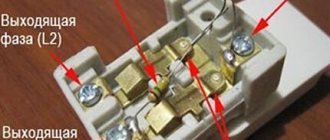
The pass-through switch does not differ in appearance from a regular one. Its front movable panel also shows up and down arrows. A typical switch has one input and one output. In contrast, a pass-through device has one input and two outputs. This indicates that the current is not interrupted here, but is redirected to any of the outputs.
Despite the fact that experienced electricians will be able to identify a pass-through switch by eye, reliable manufacturers produce products with a drawn electrical diagram of a double pass-through switch, triple or single, which is located under the device body.
You can also determine that it is a single pass-through device before your eyes by examining the terminals with copper contacts. There should be three of them. To make sure that the terminals are not mixed up with each other, you should use a multimeter. The device should be put into beep mode and its input and output should be ringed. If the multimeter emits a signal when you touch a contact, there is a contact at that location.
Scheme of distribution of connections in the network
Another difference from a simple switch is that the pass-through device has three-wire switching, and not two-wire, like a regular one. This is a kind of switch that redirects voltage from one contact to another.
Pass-through switches usually work in pairs to control one light source. A zero and a phase are supplied to each. Changing the position of the switch key closes the circuit, which causes the light bulb to light up. When the first or second switch is turned off, the phase wiring opens, and the contact of the paired switch closes, and the light goes out. That is, when the keys on both devices are in the same position, the lighting turns on, in different ones it turns off.
You can control lighting not only from two places, but also from three or more. To do this, it is necessary to add one or more cross switches to the general circuit for connecting a pass-through switch from two places.
Reason one: PUE requirement
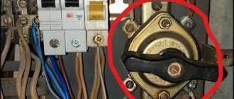
The PUE clause 4.1.9 states: “Chopping-type devices must be installed so that they cannot close the circuit spontaneously, under the influence of gravity. Their moving live parts in the off position, as a rule, should not be energized.”
Let's give an example from life. Electricians at the substation inspected the protection devices in the 0.4 kV switchgear. To cut power, they turned off the disconnect switch supplying the 10 kV substation. The disconnector was switched off from top to bottom and was locked with a padlock for safety. During the work, a high-voltage insulator fell from the support where the disconnector was located and hit the switch. If it had been in the upper position when turned off, it could have turned on due to an impact (it would have fallen down), and the electricians would have come under voltage. Fortunately, this did not happen, since the switch was installed in accordance with the requirements of the PUE.
Let us also add that in circuit breakers, in order to lift the button up, it is necessary to apply force, since there is a rigid spring inside. But to turn it down, just press a little and the button fires itself.
Advantages of installing a pass-through switch
Pass-through switches allow you to control room lighting from two or more places, which is an undeniable convenience. This is especially valuable for multi-story houses with flights of stairs. Here you can install the first switch on the first floor and the next on the second, which will turn on the light downstairs and turn off the upstairs.
The use of walk-through switches for controlling the lighting of staircases is especially important.
A good solution is to install one switch at the entrance to the bedroom, and a second near the head of the bed, which will allow you to enter, turn on the light, get ready for bed, lie down and turn off the light. It is also advisable to install switches at the entrance to a house or apartment and at the end of the corridor.
Helpful advice! Using special motion sensors or a timer built into the switch, you can automatically turn off the lighting when leaving a certain place.
Walk-through switches have significant advantages compared to conventional devices:
- high reliability and safety of operation;
- instant shutdown of the power supply to the premises, if necessary, from any point;
- optimal energy consumption;
- low cost;
- simple installation that does not require the involvement of specialists;
- no complicated settings.
The presence of walk-through switches allows you to turn on the lamps below with one switch, and when going up the stairs, turn them off with another
Basics
To turn on magnetic starters and contactors, push-button posts are used. These are devices that have 2 or 3 buttons such as “Start” and “STOP” or “Forward”, “Back” and “STOP”, there are other less common options. These buttons are a non-latching button with a normally closed and normally open pair of contacts.
Starters and contactors are electromagnetic switching devices. In order for its power contacts to close, voltage must be applied to the coil. It will attract the core (anchor) on which the contacts are attached (the design may vary). When you remove the voltage from the coil, the device will turn off and its power contacts will open.
In addition to power ones, these devices have block contacts (usually several groups of them). They are not able to withstand heavy loads, but are designed to implement a self-retaining circuit and indications. The fact is that if you simply apply voltage to the coil through the push-button post, the device will turn on, but when you release the button, it will immediately turn off. This is necessary, for example, in winches and other lifting mechanisms, but not in circuits that operate for a long time without stopping, such as lights and electric motors of ventilation systems.
To avoid this, a self-retaining circuit is needed - a normally open block contact is connected in parallel with the “START” buttons on the push-button station.
Typically, such switching devices are used to connect high-power electrical appliances to the network: heating elements, motors, or, in our case, large lighting installations.
How to make a pass-through switch with your own hands
Despite the fact that at first glance, regular and pass-through switches have minor differences, their cost is significantly different. You can buy a pass-through switch 1.5-2 times more expensive than a simple switch. Therefore, many craftsmen strive to make a switching device themselves.
To get a pass-through single-key switch, you need to use conventional single-key and two-key devices of the same size and manufacturer.
Helpful advice! When purchasing a two-key pass-through switch, the diagram of which is printed on the body of the device, you should make sure that it has the ability to move the terminals in places in such an order as to ensure that the circuit is broken and closed independently of each other.
The process of converting a simple switch into a walk-through switch consists of the following steps:
- on a surface-mounted single-key switch, the key equipped with clips is removed;
- the switch core is carefully squeezed out;
- the housing clamps on the internal mechanism of the switch are pressed out;
- one of the terminals is removed from the socket;
- one contact is reinstalled opposite the other;
- a rocker arm is installed on the contacts;
- the body is put back together.
Using pass-through switches will be convenient if the house has long corridors
You can also assemble one switch from two simple ones. They should be placed next to each other so that when the top part of the key is pressed, one is activated, and the bottom – the other. The keys should be connected with a plate that is glued on top. It is imperative to install a jumper between two adjacent contacts.
Regulations
To date, no regulatory document has clear instructions on how to install a light switch, but by analogy with other switching devices, the light should turn off when the lever or key is moved down.
These requirements are contained in PUE 7, paragraph 4.1.9. It is stated here that switches and disconnectors must be mounted in such a way as to prevent switching on when heavy objects fall on the handle or when exposed to their own weight. Accordingly, the on position for these devices is the top one, and the bottom position is off.
How to correctly install a light switch - up or down was indicated in the Construction Norms and Rules (SNiP and GOST R 50571. 1-93), where it was stated that household switches should turn off the light when you press the bottom edge of the lever or key, but in 2010 year, these documents were replaced by new ones that do not contain this requirement.
Nowadays, whether the light is turned up or down on a switch is a matter of preference for the home's occupants or designers.
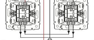
Connection diagram for a pass-through switch with 2 places
The circuit of a pass-through switch from two places is carried out using two pass-through single-key devices that work only in pairs. Each of them has one contact at the entry point, and a pair at the exit point.
Before connecting the pass-through switch, the connection diagram clearly displays all the stages; you should de-energize the room using the appropriate switch located in the control panel. After which it is necessary to additionally check that there is no voltage in all wires of the switch. To do this, use a special screwdriver.
Helpful advice! A similar check must be performed at the installation sites of switching devices.
To complete the work you will need: flat-head, Phillips and indicator screwdrivers, a knife, side cutters, a level, a tape measure and a hammer drill. To install switches and lay wires in the walls of the room, appropriate holes and grooves must be made in accordance with the device layout plan.
Unlike conventional switches, pass-through switches have not two, but three contacts and can switch the “phase” from the first contact to the second or third
Important! It is impossible to install a pass-through switch in place of a simple switch.
Wires must be laid at a distance of at least 15 cm from the ceiling. They can be placed not only in a hidden way, but also placed in trays or boxes. This installation makes it possible to quickly carry out repair work in case of cable damage. The ends of the wires must be inserted into installation boxes, in which all connections are also made using contactors.
Procedure for installing pass-through switches at 2 points: connection diagram
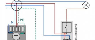
All actions for installing switching devices are carried out on the basis of a connection diagram of 2 places of pass-through switches, which can be found on the Internet. It differs from the installation of conventional switches, since there are three wires instead of the usual two. In this case, two wires are used as a jumper between two switches located in different places in the room, and the third is used to supply the phase.
Any type of lamp can be used as a lighting source in such a scheme - from conventional incandescent lamps to fluorescent, energy-saving and LED
Five wires must be suitable for the distribution box: power supply from the machine, three cables going to the switches, and a connected wire directed to the lighting fixture. When constructing a connection diagram for a single-key pass-through switch, three-core cables are used. The “zero” and grounding wires are led directly to the light source. The brown phase wire, which supplies current, passes through the switches, according to the diagram, and is output to the lighting lamp.
Helpful advice! To avoid problems with future wiring, it is recommended to use copper wires with a cross-section of at least 2.5 mm2.
The switches are connected at the break in the phase wire, and the zero, having passed through the distribution box, is directed to the lighting fixture. Passing a phase through the switch will ensure safety during repair and maintenance of the lamp.
Installation of a pass-through switch consists of the following sequence of actions:
- the ends of the wires are stripped of insulation;
- using an indicator it is necessary to determine the phase wire;
- using twisting, the phase wire should be connected to one of the wires on the first switch (white or red wires are used here);
- the zero terminals of the switches are connected by wires;
- connecting a separate wire of the second switch to the lamp;
- in the junction box the wire from the lamp is connected to the neutral wire;
When installing pass-through switches yourself, you need to take care of safety precautions
Helpful advice! If twists are made, they should be soldered and wrapped with electrical tape.
Independent search for the cause of the malfunction
If an energy-saving lamp used in a lamp or other product begins to blink, then you need to start fixing the problem immediately. Since each lighting device has resource limitations in terms of the number of starts.
That is, each such cycle reduces the operating time, and if they are repeated frequently, then in just a few days the service life will be reduced by many months, or even years. In addition, as mentioned above, if the wiring is faulty, there may be a threat to the health of the home owner, his family and friends, which should not be allowed.
Troubleshooting should only be carried out by a trained technician, using a special tool in compliance with all safety measures provided for in the governing documents.
The troubleshooting procedure should begin with the simplest methods that do not require costs. And if they don’t give results, then move on to more complex ones.
So, first of all, you need to check the functionality of the light bulb itself. Why can it be moved to another place, tested with neighbors and acquaintances. If the blinking continues, then you just need to replace the lighting fixture.
When, after installing the lamp in a new location, the malfunction does not appear, then the switch should be replaced. In order not to waste money, you can take it from another place for testing and, preferably, it should be without a backlight. When the cause is identified, you should simply buy and install a new switch.
If this does not produce results, then the owner of the premises should look for a problem in the wiring. But when performing any electrical work, it is important to remember that all of it is potentially dangerous. Therefore, you need to follow measures to prevent and avoid risky situations, have sufficient skills and have the appropriate tools.
The information in the following article will help you find out the reason why the LEDs glow after disconnecting from the power supply.
Pass-through switch: connection diagram from three or more places
If there is a need to control lighting fixtures from different places, then you should implement a 3-point pass-through switch connection diagram. This is true for multi-story buildings, large halls, long corridors with several exits. To do this, you will need, in addition to the two conventional pass-through switches, a cross switch. In such a switching device there are not three, but four contacts: one pair of input and two output, which switch simultaneously. To do this, use a four-core cable.
Connection diagram for three pass-through switches
In the connection diagram for pass-through switches from 3 places, conventional switches are used at the first and last point, between which a cross switch is installed.
Helpful advice! Since wiring in the distribution box with each additional point involves a large number of wires, it is recommended to label the wires.
The connection diagram for pass-through switches from three places will look like this:
- “zero” and grounding are output to the lamp;
- connecting the phase to the input of the first pass-through switch;
- using wires, the output contacts of the first switch are connected to the input pair of crossover switch terminals;
- connecting the output wires of the crossover switch to a pair of terminals at the output of the second pass-through switch;
- the wire from the second switch is supplied to the lamp;
- the second wire, which comes from the lamp, comes to the junction box at “zero”.
If lighting control is planned from a larger number of places, additional cross-switches are introduced into the overall circuit, which are connected according to the above principle.
A three-wire cable is supplied to each pass-through switch, and a four-wire cable is supplied to the crossover switch. All wires used for connection must be of the same cross-section. Switches that can operate at normal currents of 6.10 and 16A must have the same rating. A visual diagram for connecting pass-through switches from 3 places can be seen on specialized websites on the Internet.
The procedure for connecting a pass-through switch is not much different from connecting a conventional switch
Contactless key reader
This option is much more convenient and reliable.
Probably everyone has a drop key on their keys for a gate or intercom:
On the wall we will need to place a key reader with a built-in controller, for example, Matrix IIK
From the outside it looks like a white rectangle with a small LED. You need to supply 12V power to it; there is a relay on the board. There are two operating modes: sending a short pulse when a programmed key is applied, or turning the relay on/off when a key is applied. You can program all your keys. Any EmMarine format keys (drop keys) are supported, as well as contactless cards of this format. There are models that support more copy-protected, but less common Mifire cards.
Works with both contactors and pulse relays. The most interesting thing is that this reader can be hidden by completely covering it with wallpaper, for example. The reading range is about 1-2 centimeters. The main thing is not to cover it with metal elements.
That is, firstly, it can be invisible, secondly, you do not need to carry a separate key or card, and thirdly, it cannot be activated accidentally.
This reader is intended for access control systems; it has a connector for connecting an “exit button”, upon pressing which the controller will also change the state of the relay or give an impulse. You can display this button somewhere and use it as a backup option in case you lose the key.
Connection diagram for a two-key pass-through switch
Using pass-through switches, you can control not only one lamp, but also a group of several lighting fixtures. To do this, connect pass-through two-key switches. Each of them has six contacts. Common wires are determined according to the same principle as for conventional devices, but a larger number of wires need to be wired.
The difference between the double pass-through switch wiring diagram is that more wires are used here. The phase is supplied to both inputs of the first switch. Wires should go out from the two inputs of the second switch to two lamps. In the case of organizing lighting control from three or more points, two cross switches should be installed for each of them, since they are only available as single-key switches.
Connection diagram for a pass-through two-key switch
In this case, according to the principle of connecting double pass-through switches with crossover switches, the first pair of contacts should be connected to one crossover, and the second to the other. If necessary, the devices are connected to each other. The output of both crossover switches must be connected to the last two-key transfer device.
Control circuits
Electromagnetic contactors do not have mechanical locking in the on position. To ensure that the rod is held during operation, a self-retaining circuit is used. This is a fairly convenient technique that allows you to switch the coil power circuit with various protection and automation devices of the electric drive. The exception is assemblies controlled by PLC or relay automation.
The simplest self-retaining circuit includes one additional blocking normally open contact. The coil power circuit is connected through a normally open contact of the start button. The second circuit is connected in parallel; it consists of a series-connected blocking contact and a normally closed contact of the “Stop” button. Thus, when the contactor is turned on, a blocking contact is closed, which is held during operation and supplies power to the coil. If it is necessary to stop, the coil power circuit is opened with the “Stop” button.
Contactor self-retaining circuit: L1, L2, L3 - three-phase power supply phases; N - neutral; KM - magnetic starter coil; NO13-NO14 - additional normally open contact; M - asynchronous motorThere are also more complex control schemes
Thus, the use of a normally closed contact of the start button of one contactor can be used to prevent the simultaneous operation of two starters, which, in particular, may be important when constructing reversing circuits or may be due to other technological needs. The same principle can operate when using a normally closed blocking contact of one contactor, which is connected in series with the start button contact of another.
Scheme of reverse engine starting: KM1, KM2 - coils of magnetic starters; NO KM1, NO KM2 - normally open contacts of starters; NC KM1, NC KM2 - normally closed contacts of starters; KK - thermal relay
The self-retaining circuit can also include limit switches, dry contact sensors and various protective devices. Automatic activation of the contactor is also possible; for these purposes, the button is replaced or duplicated by parallel activation of limit switches or sensors. Thus, the complexity and control schemes of an automated electric drive are practically unlimited.
Well-known manufacturers of pass-through switches
The Legrand company occupies a leading position in the electrical goods market. The demand for Legrand pass-through switches is due to the high quality of the products, ease of installation, ease of further operation, stylish design and flexible pricing policy. The only drawback is the need to adjust the installation location. If it does not coincide with the product, difficulties may arise during its installation, which is carried out according to the connection diagram for the Legrand pass-through switch.
Legrand pass-through switches
A subsidiary of Legrand is the Chinese company Lezard. However, the products have only a stylish design left from their native brand. The build quality is much lower, which is due to the low cost of the products.
One of the leading domestic manufacturers of electrical goods is the Wessen company, which is part of the Schneider Electric company. All products are manufactured using the latest technologies on modern foreign equipment and comply with European quality standards. The models have a universal, stylish design that allows each element to fit into any interior of the room. A distinctive feature of Wessen switches is the ability to replace the decorative frame without dismantling the device.
Another equally well-known manufacturer is the Turkish company Viko. The products are characterized by high quality workmanship, reliability and durability, and comply with electrical safety requirements and European quality standards. In the manufacture of the device body, fireproof durable plastic is used, which is designed for a large number of operating cycles.
A pass-through switch, unlike a regular switch, has three conductive wires
The Turkish brand Makel offers high-quality, reliable, safe and stylish products. Thanks to the ability to connect a cable without the need to use a distribution box, installation of switches becomes simpler, and further operation becomes comfortable and safe.
Popular range of pass-through switches
Legrand pass-through switches from the Velena series are distinguished by their stylish design and a variety of color variations. Here are one- and two-key products that have a dust- and moisture-proof layer. You can buy a switch from 300 rubles.
The Celiane series includes products with circular keys inscribed in a square. They can be non-contact with levers or silent. The cost of switches starts from 700 rubles. The Exclusive Celiane range features a limited number of switches handcrafted from marble, bamboo, porcelain, gold, myrtle and other materials. Frames are made exclusively to order. The price for the product starts from 5.9 thousand rubles.
Color solutions for switches from the Celiane series
The most popular series of switches from Lezard are Demet, Mira and Deriy. Here are products made from non-flammable polycarbonate, which meets electrical safety requirements. The conductive elements are made of phosphor bronze, which is characterized by high conductivity and low heating. You can buy a pass-through single-key switch from 125 rubles.
The W 59 Frame series from Wessen uses a modular principle, allowing you to install from 1 to 4 devices in one frame horizontally or vertically. The price of the product is 140 rubles. Single and double pass-through switches from the Asfora series are distinguished by a simple design, but high quality workmanship, which can be purchased for 450 rubles.
Among the popular series of the Makel company we can highlight Defne and Makel Mimoza. The device body is made of high-quality plastic, equipped with an internal reliable mechanism. The cost of products starts from 150 rubles.
When you press the on/off button, the moving contact of the pass-through switch switches from one contact to another, thereby creating the conditions for a new circuit in the future
The operating principle and installation of switching devices do not pose any significant difficulties. It is necessary to first study the connection diagram and follow the recommendations of electrical safety rules, which will make it possible to carry out reliable and safe installation of devices, thereby ensuring convenient and comfortable control of lighting devices in the house.
How to connect a pass-through switch: video connection diagrams
Pass-through switch: diagram for connecting a device from different places
Share the news on social networks
- Related Posts
- Threshold for tiles and laminate: how to properly place it between coverings
- Comfortable bathroom
- Standard sizes of interior doors. Accurate measurement of structures
« Previous entry
Using thermal relays with magnetic starters
The possibility of triggering the thermal relay (1) is provided in case of an emergency. The circuit contact (4) is broken, followed by disconnection of the coil and return of the core to its original state by special return springs. After disconnecting the contacts in this way, the dangerous voltage is removed in the emergency area.
Connecting a magnetic starter together with a thermal relay provides reliable protection of electrical units from possible overloads. These devices serve as an effective addition to automatic machines, the bimetallic strips of which cannot always protect during an accident. Although, the principle of operation of a thermal relay is the same as that of the thermal element of an automatic protective switch. However, the thermal relay does not automatically switch off, but only sends a set signal to perform this operation. It must be accurately and competently recognized, and put into practice in a timely manner.
A thermal relay equipped with power contacts can be directly connected to a magnetic starter without the use of conductors. However, products from different manufacturers may not match, fit or interact with each other.
Each thermal relay is equipped with two groups of contacts, independent of each other - normally closed and normally open. To break the circuit, a closed contact is used, operating through the STOP button. All working contacts are present in the circuit intended for control. They are connected directly next to the coil, but can be placed in other convenient places.
The actuation process of the thermal relay is completely invisible from the outside. Returning to the original state is carried out using a small button located on the panel. You do not need to transfer the contacts immediately, but only after the relay has cooled down, otherwise they will not be securely fixed. Before the very first use, it is recommended to press the button to avoid careless switching during transportation.
Wiring: open or hidden option
Despite the fact that installing a switch may seem like a very simple matter, there are a large number of nuances that a novice electrician must know.
First you need to decide on the type of wiring.
Open wiring is still used in everyday life. It is especially loved by designers who create interiors in retro or loft style.
Electrical wiring is an essential element present in every home.
There are two types of it:
- Open. The wires are laid on top of the wall. They can be secured with decorative rollers or covered with plastic cable ducts.
- Hidden. The wire is laid inside the wall. To do this, channels are cut into its surface into which the cable is laid. After installation, the grooves are sealed with mortar.
Each type of wiring uses a different type of switch. For an open system, choose overhead models that are placed directly on the wall. They are easily recognizable because they are very visible on the surface.
This type of switch was the first to appear and has changed little over the past decades. For closed wiring, internal or built-in models are used.
They are installed in a recess that is previously prepared in the wall. The dimensions of the hole are selected depending on the dimensions of the switch. It is attached inside the recess using special spacer legs.
There is another type of built-in devices - with mounting plates. This option is more convenient to install. After installation, the internal switches practically do not protrude above the wall plane.
Switch instead of master button
The most basic load sharing is organized using an additional switch in the electrical panel. No, not like that