To perform basic electrical work, it is absolutely not necessary to call a specialist. Knowing how to connect an LED switch, you can install it yourself. Agree, this skill will be especially useful if there are major repairs and updating of electrical wiring.
We will tell you about the connection diagram, installation method and difficulties that may arise during installation. You can also improve an ordinary switch with your own hands by making it backlit.
How a backlit switch works and works
We will describe the design of an LED switch using the example of a two-key backlit device.
The mechanism consists of the following elements:
- one input, two output terminals;
- current limiting resistor;
- moving contacts.
The design also includes a housing, a decorative panel and key pads.
Some models of backlit switches have a ready-made connected backlight mechanism. They also produce models in which the backlight conductors need to be connected to the terminals independently.
When the contacts of the LED switch open, the current flowing through the phase wire flows to the resistor, then to the LED or neon lamp. Next, the voltage passes through the lighting fixture and exits through zero.
Since the backlight is connected through a current-limiting resistor, the voltage in the network decreases and is enough for illumination, but not enough for the chandelier to operate.
This is how an LED switch works. If the lighting lamp burns out or is unscrewed, the circuit will be open and the backlight in the device will not work (+)
After the switch contacts close, the current, which always moves along the circuit with the least resistance, passes through the network that powers the lighting lamp - in this circuit the voltage is practically zero. The current also flows to the backlight circuit, but it is so small that it is not enough even to operate a neon lamp.
The circuit includes a current-limiting resistor and an LED or neon lamp. Otherwise, the design and connection method are the same as for a conventional device (+)
Step-by-step replacement instructions
Before work, turn off the power supply
You can replace the switch with a dimmer yourself. You need to follow the replacement instructions - turn off the lighting, remove the switch and install the regulator.
Before performing any electrical work, turn off the power supply to the room. To do this, you need to turn off the electricity in the panel on the site or inside the apartment.
First of all, you should remove the decorative panel from the switch. Then the internal mechanism connected to the wires is pulled out. The last step is to disconnect the conductors. The cores must be carefully pulled out of the terminals, keeping them intact.
If the wires are in good condition, there is no need to perform preparatory procedures. You should study the dimmer connection instructions, which outline the basic requirements and wiring diagram for the wires. Then you need to apply power and check the functionality of the regulator. If connected correctly, the brightness will gradually increase and decrease.
Application of LED Switch
A backlit switch is installed where it is dark even during the daytime, and constant use of the lighting device is impractical. It is also used in rooms where access is required at night.
A switch with LED backlight, just like a regular one, can be solid-body or consist of one, two or more keys
The more light sources, the more keys on the switch will be required. To control lighting consisting of more than three lighting fixtures, dial switches are used, which are installed in one row.
To control lighting from several places, purchase a special backlit switch.
Other causes of flickering
The above methods for eliminating the flickering of lamps with LED lamps are related to the switch. But there are exceptions when the light flickers and the switch is compliant.
In conclusion, it should be noted that if you postpone the search for a solution to the cause of the flickering light bulb, the energy-saving device will soon fail.
LED lamps are designed in such a way that each blink means the device is turned on. The service life of the lamps is tied to the number of switches on/off: the more often it flickers, the faster it will burn out. While repairing the lighting fixture, you can replace the LED with an incandescent lamp or temporarily install a regular switch.
Source
How to choose an LED switch
When buying an LED switch, there is no need to chase expensive ceramic devices, since the power consumption of lighting devices is generally not very large.
For domestic use, it will be sufficient to use a high-quality plastic LED switch with a reliable contact group. The service life of such devices is about 40,000 switchings.
For hotel rooms, illuminated switches are used, which are controlled using a key card. They can be with or without a shutdown time delay
The choice is also made based on the design of the device, the type of inclusion - they produce keyboard and rotary, push-button, touch and cord.
Depending on the installation method, internal and external devices are distinguished. The case material can also be different - plastic, glass, copper, stainless steel are used, and slate, gold plated and even leather are used as decorative coatings.
But what you really need to pay attention to is the protection class (IP) - it indicates the possibility of using the equipment in certain conditions.
For example:
- An IP class of 20 indicates that the device is poorly protected from dust and moisture. Such equipment is used in residential premises.
- Class IP 45 and higher is used for marking switches suitable for connection in rooms with high humidity - baths, saunas, kitchens, toilets, etc.
- An IP class of 65 means that the switch can be used outdoors. Such electrical equipment has increased protection from dust and moisture. Installed outside the building - under the porch, canopy, on covered verandas. It has more massive keys, and at the point where the electrical wire enters there is a rubber seal.
The higher the class, the more protected the device is from external factors. This applies not only to switches, but also to sockets, toggle switches, and other electrical equipment.
Pulse relay for installation in a distribution box
In addition to panel-mounted options, there are also mounted ones, for installation behind a suspended ceiling or directly into a distribution box.
With their help, you can organize the switching of lighting in your apartment from single-key switches to pulse switches. You replace the switches in the wiring boxes with buttons and switch the wires in the junction box.
This is what this diagram looks like when connecting a pulse relay directly in the distribution box under the ceiling.
Scheme No. 3
At the same time, little changes in your electrical panel, and you get an excellent lighting control option, similar to walk-through switches.
When connecting several lamps at once from a standard impulse switch in a switchboard room, rather than just one light bulb, be sure to install a cross-module or terminal blocks.
It is unlikely that it will be possible to run two or three cables per relay (the limitation on the thickness of the wire will not allow it). You'll have to scatter them across different pads.
What other types of pulse relays exist? For example, there is a time delay function.
It can be used to delay both when the light is turned on and when it is turned off. You leave your own cottage in the evening and press a special button in the house.
This gives you time to calmly walk along the illuminated paths to the gate and only after that the light will automatically turn off.
This method does not even require the installation of separate switches on the street.
You can also connect an exhaust fan in the bathroom to such relays. When leaving the bathroom, you press the button, and the fan continues to run for the period of time you set.
What are the disadvantages of impulse relays? Some models from certain manufacturers are sensitive to voltage surges.
What does this mean? And the fact that the light on some lamps will turn on and off spontaneously when the voltage is unstable.
Many people are also annoyed by the constant clattering and clicking when the relay operates. Electrical mechanical varieties are especially prone to this. They consist of a lever and contact system, a coil, plus a spring.
You can distinguish them by the lever on the front side. With its help, the relay is manually moved from one position to another.
The electronic ones have a built-in board with a microcontroller. There's not much to rattle about in them, and they're less noisy.
To reduce problems, choose relays from well-known and long-established brands. Such as ABB (E-290), Schneider Electric (Acti 9iTL), F&F (Biss) or the domestic Meander (RIO-1 and RIO-2).
ABB has a very large selection of adding all sorts of overlays and additional “goodies” to the main E290 model.
Meander RIO-2 has a useful function for working with conventional single-key switches.
To do this, this relay needs to be switched to mode No. 2 and a light switch (3 in total) must be connected to each of the inputs Y, Y1 and Y2.
As a result, you will get a cross-switch operating mode based on conventional single-key switches. When you press any of them (on or off), the output will change and the contacts on the relay itself will switch, turning on or off the light bulb.
How to carry out installation correctly
The illuminated switch mechanism involves a small lamp that glows when the switch is turned off. A small neon lamp or LED along with a resistance element can be used to illuminate the device. The backlight has wires that need to be connected to power during installation.
Preparing for installation and mandatory safety precautions
Without basic knowledge of safety precautions, it is better not to start working with electrical equipment at all. Illiterate electrical installation can lead to electric shock, failure of electrical appliances, and fire.
Basic rules of behavior when working with electricity:
- all work must be carried out in a de-energized network;
- it is unacceptable to overload the power grid;
- check the markings of the wires for compliance with the connected network;
- It is better to replace a damaged section of the network rather than repair it;
- Do not touch connected equipment with wet hands.
A regular indicator screwdriver or multimeter will help determine the nature of the conductors - where is the zero and where is the phase. The indicator is sufficient if the electrical network is single-phase. To analyze a three-phase network, use a multimeter.
Bringing one of the multimeter tentacles to the phase, the other is fixed on any of the conductors. The range for alternating current is set to 220 W. Zero upon contact will show a value of about 220 W, grounding is always lower
Installation example of a 2-gang switch with backlight
The main design differences between LED switches are in the backlight mechanism. It can be ready to use and does not require any action to connect it. Another type of design requires connecting wires that power an LED or neon lamp.
Let's consider a more complex option - how to connect a backlit device, in which the conductors need to be connected independently.
A design feature that allows easy access to the backlight wires can be useful if you need to turn it off
First of all, pry up the keys with a screwdriver or other suitable tool and remove them. Separate the core (internal mechanism) from the body.
Next, determine the correct position of the switch using an indicator. To do this, by touching the contacts with a screwdriver on one side and an indicator on the other, check whether the device is on or off.
If the indicator lights up, it means it is turned on. In this state, turn it so that the keys with the pressed side are located on top.
For a regular indicator screwdriver to work, you need to hold it correctly - the metal part must touch the contact plate, and the top must be touched with your thumb
One of the wires coming from the indicator is connected to the input terminal, and the second is connected to the key contact. If there are several keys, then the wire is connected to the first of them, starting from the left. Simultaneously with the wire going from the indicator to the input terminal, the phase conductor is also connected.
The two outlet phase wires that go to the chandelier are connected to the output terminals simultaneously with the second backlight wire, making sure that it does not fall out of contact.
With this connection method, the backlight will turn on after opening the contacts using the first key. The second will not have any effect on turning off the backlight, and the light will remain on even when the lighting is on.
In order for the indicator light to go out when you press any of the keys, you need to make a jumper yourself that will connect the indicator to both keys.
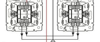
If you do not take into account the connection of the backlight, installation proceeds as in a conventional device. A phase conductor is led through the junction box to the switch and connected to the input terminal L, inserting it into the hole and screwing it in with a screw.
Next, two outlet phase wires are connected to the device contacts L1 and L2, which also lead to the chandelier through the junction box. One of them is connected to one lamp, the other to the other two. The zero passes through the junction box in the wiring box, then goes to all the chandelier lamps, closing the contact.
As a result of correct connection, the first key will turn on one lamp, the second two, and two turned on keys will lead to the activation of the entire lighting device. When switched off, the LED (+) should light up.
Step-by-step instruction
Before you begin the process of installing a switch with your own hands, I would like to remind you of one very important rule. Switches always and everywhere operate only on phase breaks
They should not break the zero. Therefore, when switching wires to switch contacts, it is so important to accurately determine the phase conductor. If you confuse zero and phase, the switching device will not stop working. But the lamp socket will always be energized. When replacing a burnt-out light bulb, there is a risk of electric shock to a person.
Switches always and everywhere operate only for phase interruption. They shouldn't break zero
Therefore, when switching wires to switch contacts, it is so important to accurately determine the phase conductor. If you confuse zero and phase, the switching device will not stop working
But the lamp socket will always be energized. When replacing a burnt-out light bulb, there is a risk of electric shock to a person.
So, the mounting box is installed in the wall, two wire strands are inserted into it. You can begin direct installation of the switching device:
- The first step is to determine the phase wire. Take an indicator screwdriver and touch both wires one by one. If the indicator window on the screwdriver lights up, it means that this wire is a phase; you can carefully mark it with insulating tape.
- Now turn off the circuit breaker that supplies voltage to the room or the common one to the apartment. Again, using an indicator screwdriver at the work site, check that there is no voltage. Touch it to the newly discovered and designated phase wire; the screwdriver should not glow.
- Take the switch in your hands, using a flat-head screwdriver on the left or right, lightly pry the key and remove it.
- Unscrew the two screws that secure the protective frame and remove it.
- There are two contact screws at the top of the operating mechanism. On many models they are marked. For example, the numbers “1” and “3”, or the English letter “L” and an arrow pointing down, respectively, these symbols indicate incoming and outgoing contacts. Unscrew these screws.
- Strip the wires inserted into the socket box from 1 cm of insulation. Insert the phase wire into the hole in the incoming contact, and the second core into the hole in the outgoing one. Tighten the screws and check that the wires are well secured. If there is any loosening, be sure to tighten it tighter, because poor contact will lead to burning and further damage to the switch. But there is no need to overdo it here, so as not to break the screws.
- Right there on the working part there are two more spacer screws. Unscrew them, place the working mechanism in the mounting box, carefully align them horizontally and fix them in this position by tightening the spacer screws. Check your work, try to slightly shake the working part. If it is securely fixed in the socket box, install a protective frame on top, screwing it with two screws.
- Attach a key to the drive of the operating mechanism and check how the installed switch works. To do this, turn on the input machine. Press the switch key, the light bulb in the lighting fixture should light up. When you press the key back, the light should go out.
In modern models of switches, plug-in contacts are often used instead of screw ones; they have proven themselves quite well. The wire must be inserted into the contact hole; it must fit tightly and rest against it. If you try to pull the wire back, then with a certain force it should not be pulled out, this means that the contact is good. Just don’t use all the strength you have! And so that if necessary, you can pull the wiring out of the contact hole, there are special levers there.
For more information about installing the switch, watch this video:
https://youtube.com/watch?v=FP3_fqpoNdQ
The essence of installing a two- or three-key switch is the same, the only difference will be in the connection diagram itself. And if you figure out how to properly install a regular switch with your own hands, then you can probably handle more complex switching devices.
Why do energy-saving lamps blink?
The LED switch is not compatible with energy-saving lamps. A device conflict manifests itself in a short-term flashing of the lamp when it is off or in the so-called smoldering mode, when the lamp does not turn off completely, but barely glows.
The service life of an LED or energy-saving lamp in the wrong mode is significantly reduced and ranges from one to two months
This happens because inside the fluorescent lamp there is an electronic converter (capacitor), which, gradually recharging from the current passing through the backlight lamp, flares up.
A similar phenomenon occurs with LED strip power supplies, which also have a capacitor and are powered by a small current coming from the backlit switch.
Manufacturers of energy-saving lamps indicate that the use of their products is not compatible with the use of LED switches and dimmers.
You can get around this limitation by controlling the operation of the lighting device using a relay. From the switch, the command first goes to the relay, which directly controls the lighting.
The relay is produced by many manufacturers of electrical goods: Schneider Electric , ABB , Siemens . You can place it under the chandelier cap, behind the cornice in which the LED strip is installed.
You can use another solution to the problem - disconnect the neon lamp or LED from the power supply. This can be done by disconnecting the backlight wires from the terminals. But then the LED switch will lose its advantages.
Let's consider solutions that still allow you to combine lighting and the use of energy-saving lamps.
Resistor resistance and power
The above resistor parameters correspond to a 220 V network voltage. It happens that the LED lamp is powered from a line of a different rating. Then you will have to calculate the resistance and power of the resistor yourself.
We calculate the resistance using the formula R=∆U/I, in which ∆U is the difference between the actual voltage in the device’s power supply line and the lamp voltage, I is the LED current.
The light bulb will work normally if the resistor value is in the range of 150 - 510 kOhm.
We calculate power using the formula P=∆U×I, where the letter values are similar to the above explanations.
Knowing these formulas, it is easy to make the necessary calculations of the resistor value.
DIY illuminated switch
During the operation of electrical equipment, it sometimes turns out that in some of the rooms it would be nice to have a backlit switch. To do this, you don’t have to buy a device - you can improve your old one yourself.
What you will need for this:
- regular switch;
- LED with any characteristics;
- 470 kOhm resistor;
- diode 0.25 W;
- the wire;
- soldering iron;
- drill.
Using a soldering iron, they begin to assemble the circuit. The cathode of the diode (marked with a black stripe) is connected to the anode of the LED (the anode has a longer leg). The resistor is soldered to the positive terminal of the LED and to the wire that will serve as the connection to the switch. The second wire is connected to the cathode of the LED.
If you do not have a resistor of suitable power at hand or there is not enough space for placement, then it can be replaced with two resistors of lower power by connecting them in series (+)
Next, connect everything to the on-off mechanism. The phase conductor that leads to the lamp is connected to the terminal along with one of the wires leading to the LED. Another wire is connected to the input terminal along with the phase wire, which supplies current from the mains.
It is necessary to carefully insulate the exposed sections of the wire and prevent the conductors from touching the housing; this is especially important to do if it is metal.
Check the connection diagram of the backlit switch for functionality as follows: the key, closing the contact, causes the chandelier or lamp to light up; when it is off, the LED lamp lights up. If the circuit works correctly, you can install the device in the housing.
To make the lighting visible, place the LED lamp into a drilled hole at the top of the housing. This is not necessary if the body is light - the light will break through it.
The switch can be illuminated using a neon lamp. The circuit uses a HG1 gas-discharge lamp and any type of resistance with a nominal value of 0.5-1.0 MOhm with a power of more than 0.25 W (+)
Connection rules
Regardless of the type, installing an illuminated switch is the same. The differences are only in a couple of nuances.
Illuminated switch connection diagram - advice from electricians
The glow-in-the-dark switch is very convenient to use, so the user, if possible, strives to purchase just such a model.
Once upon a time, these devices were equipped with a phosphorescent element, but this option has disadvantages: the glow gradually weakens and may go out completely; in a room where daylight penetrates poorly, for example, in a corridor, a phosphorescent element is of no use at all, since it has nothing to “charge” with.
Therefore, today switches are equipped with electric backlighting, which works stably in any conditions. It will be discussed in our article, the topic of which is an illuminated switch: connection diagram.
Scheme for connecting an LED to a switch in an apartment
Circuit diagram and appearance of the switch
As you can see, the device consists of only two elements - a current-limiting resistor and a light source.
Many people who are not related to radio electronics may be confused by this scheme. After all, we put the LED in a 220V AC switch, although the LED itself is designed for a voltage of 2-12V DC. And the main lamp, in theory, should also glow with this connection.
Switch with on indicator
Switches with indicators differ from LED switches in a completely different principle of use - the lamp in them lights up when the lighting is turned on. The main purpose of a pilot light is to signal that lights are on in a basement, attic, storage room or outdoors.
Used to control energy consumption. The indicator can be set for each of the keys or only for one of them.
The connection and operation diagram of a switch with a backlight function is built according to the following principle. The test lamp is connected in parallel to the switch terminals. When the circuit is completed, current flows through the indicator and the light fixture - both light up. If the switch is off, no current flows to either the indicator or the lamp.
Indication of switched-on lighting can be done in combination: 1 indicator lamp per key or one lamp for each key (+)
Single color
Connecting a single-color LED strip is not difficult. All you need is to purchase the components of the backlight, cut the required length of LED strip, solder it to the power supply and insulate the exposed contacts. Now we will consider in detail each of the connection stages.
Selecting a connection diagram
To independently connect an LED strip to a 220 volt network, you must first select a diagram for connecting all the elements. If you decide to make lighting using no more than 5 meters of product, then just connect the strip to a 220 x 12 V power supply, and connect the power supply to your home network via a cord with a plug.
However, it often happens that you need to connect more than 5 meters of LED strip - 10, 15 or even 20 meters. In this case, it is prohibited to connect all segments sequentially, because the first 5-meter section will overheat and at the same time the voltage in subsequent sections will drop significantly. Such a connection will shorten the life of the LED backlight. We examined all the most popular LED strip connection diagrams in detail in the corresponding article. For example, let's provide them again.
Consecutively (allowed if you need to add a small segment):
With two power supplies (if the tape is long):
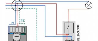
Please note that you can connect the LED strip via a switch or dimmer, which is very convenient when creating additional lighting in the kitchen or other room. In this case, the light switch is connected in front of the power supply in a phase break, as shown in the diagram below:
The dimmer must be connected after the power supply, as shown in this example:
We’ve sorted out the diagrams for connecting LEDs to a 220v network, now let’s move on to the process of connecting the circuit elements.
Connecting components
In the simplest example, we have a 220/12v power supply and 5 meters of single-color LED strip. To connect all elements to 220 volts, you need to perform the following steps:
Cut the appropriate length of the product. We have already talked about how to properly cut LED strip. You need to cut the conductor in strictly designated areas, indicated by a dotted line or a scissors icon, as shown in the photo below: Prepare the wires for connection. If the length is no more than 5 meters, you can safely choose a wire with a cross-section of 1.5 mm 2. If the tape is long, we recommend calculating the wire cross-section by power and current in order to select the appropriate value. Prepare a soldering iron, rosin and solder. Degrease the contact pads of the LED conductor using cotton wool and alcohol. Strip the wires for connecting the product by 2-3 mm for soldering. Tin the wires and pads for soldering. Solder the wires to the LED strip. It is best to use tin-lead solder for soldering.
It is important not to confuse the colors of the wires, otherwise the LEDs will not light up. The black or blue wire must be connected to the “-” terminal, and the red wire to the “+”. Insulate the soldering area using heat shrink tubing
By the way, instead of heat shrink, you can also use a glue gun, which will reliably protect the exposed contacts. Connect the wires from the tape to the power supply, also guided by the color markings. Connect a cable from a 220 volt network to terminals L, N and PE. Do not forget to turn off the electricity in your house or apartment before doing this.
That's all the step-by-step instructions for dummies on how to connect an LED strip to a power supply and network with your own hands. It should be noted that you can connect the product even without soldering, using special connectors, as in the photo below.
The disadvantage of such adapters is that over time the contact will deteriorate, which cannot be said about more reliable soldering of wires. You can see how to connect an LED strip using connectors and soldering in the video below:
Main mistake
It is worth noting a common mistake made when splicing two segments - many connect them in series. It is believed that it is enough to connect the two ends of the tape in a direct way and obtain the required length. This switching is incorrect, since the tapes must be connected in parallel.
In practice, this error leads to an increase in resistance in the circuit: towards the end of the chain, the LEDs will glow very dimly or not work at all. In this case, excess voltage will be supplied to the initial sections of the tape, which will lead to rapid failure of the lighting elements.
Also, increased voltage is fraught with increased temperature of the LED strip, which is also not a plus. It has been practically proven that incorrect connection of two pieces of tape leads to their rapid wear and significantly reduces their service life.
PKI zone illumination source pinimg.com
We use connectors
It is worth immediately noting that this method is simpler, more expensive and quite reliable.
Before you start connecting, find the contact pins. On different types of tape they are similar and are located along the cutting line. The location of the cut is indicated either by a black (white) line or the same line with a scissors icon (see above).
Connectors come in two varieties:
- For single color ribbon;
- for RGB.
The second factor by which connectors can be classified:
- Connectors with wires;
- butt connectors.
Wired connector
A connector for connecting an LED strip to wires is a type of connector that is needed for rotating connection of fragments or connection to a power supply.
To connect the LED strip and connector, you must first prepare the strip. If it is covered with a layer of moisture-proof coating, remove it to such an extent that only the contacts remain uncovered.
To clean the contact pads from oxides, wipe them with a hard eraser, a toothpick or the wooden end of a match - a soft material will not damage them, but will remove oxidation.
After preparation, place the contact pads under the spring-loaded contacts. The wires on such connectors usually have different colors:
- Plus – red wire;
- minus – black.
However, when connecting, check which of the contacts is connected to which of the wires.
This is what the RGB connectors look like. There are no differences in connection.
Wireless connector for butt connection
How to connect an LED strip without soldering into a joint? To do this, you need special connectors without wires.
Please use solderless LED strip connector. This is very convenient when replacing a failed fragment; such a connector is practically invisible and is perfect for installation work when you no longer have a whole coil, but only leftovers and trimmings.
Disadvantages of this connection method:
- Connectors, although inexpensive, still need to be purchased;
- Over time, the contacts oxidize and the circuit breaks (more details on why the LED strip does not work).
Possible problems
If you follow the rules and do everything according to the instructions, there will be no problems. The problem can only arise if you buy a “semi-finished product” . In it, the light bulb lies next to the switch in the package. But it’s hard to call it a problem. Rather, at the moment it is a small obstacle. In this case, you need to connect the two wires of the light bulb to different wires of the socket box.
If the switch is single-key. When connecting a two-key device, the indicator lamps are connected by one wire, and the others are connected to different phases. It doesn't matter which ones.
A switch with an LED differs from a regular switch only in the light bulb . No need to worry about spooled kilowatts. The backlight consumes a tiny fraction of electricity. Only works when the lights are off.