A fan is one of the unnoticeable but extremely important devices that help create favorable conditions for work, relaxation and simply having a good time.
Without it, computers, refrigerators, air conditioners and other equipment will not be able to function. To ensure the most efficient operation of various devices, use a fan speed controller.
From our material you will learn about what types of regulators there are and the features of their operation. We will also tell you how to assemble the device yourself and what you will need for this.
speed controller
into the open circuit +12V, as shown in the figure. Attention! If your fan has 4 terminals, and their colors are: black, yellow, green and blue (for these, the plus power is supplied via the yellow wire), then the regulator is connected to the gap in the yellow wire.
A ready-made, assembled fan speed controller is installed in any convenient place on the system unit, for example, in the front of a plug in a five-inch bay, or in the back of a plug for expansion cards. To do this, drill a hole of the required diameter for the variable resistor you are using, then it is inserted into it and tightened with the special nut that comes with it. You can put a suitable handle on the axis of the variable resistor, for example from old Soviet equipment.
It is worth noting that if the transistor in your regulator gets very hot (for example, if the power consumption of a cooler fan is high or if several fans are connected through it at once), then it should be installed on a small radiator. The radiator can be a piece of aluminum or copper plate 2 - 3 mm thick, 3 cm long and 2 cm wide. But as practice has shown, if a regular computer fan with a current consumption of 0.1 - 0.2 A is connected to the regulator, then there is no need for a radiator, since The transistor heats up very little.
- Simple scheme
- With temperature sensor
- To reduce noise
- Video
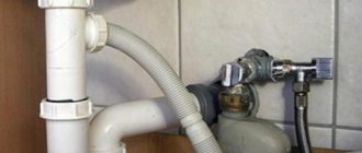
Connecting the controller to the hood
The device is installed indoors. It is produced taking into account the recirculation of air masses to cool the internal circuits.
It is prohibited to place the regulator in an area with poor air convection, direct sunlight, or above a heating device. The operating position of the device is strictly vertical, so the generated heat will be dissipated
To install the regulator correctly, you must carefully read the instructions for the device.
Most models are designed for self-installation by the user and do not require special knowledge.
The contacts on branded products are marked, and the delivery set includes recommendations for connecting, operating, and maintaining the device. Circuits differ for different devices
Installation of wall and in-wall devices is carried out using screws and dowels, which are selected in accordance with the dimensions and weight of the device. Fastening elements are usually included in the kit, as is a wiring diagram for the fan controller.
The general pattern and sequence of actions is as follows:
- The regulator is first mounted, then connected to the cable that supplies current to the fan.
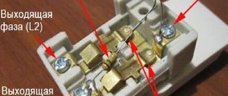
- The wires are divided into “phase”, “zero”, “ground” and cut, connected to the input and output terminals. It is important not to confuse them and make all connections according to the instructions.
- The last stage is to check the cross-sectional size of the power cable and connection for compliance with the maximum permitted voltage of the device.
The process of installing wall regulators is similar to the principle of connecting sockets and light switches. You can use the old fan switch seat to mount the controller. In this case, the switch must be removed.
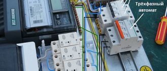
When the control module and the regulator itself are located in different housings, installation of the devices is complicated. The control unit is powered from the electrical panel, and the executive module is connected via a low-current wire
If the controller has thermal contacts, it is recommended to connect it to motors with external thermal protection contacts connected to the TK terminals of the regulator. This circuit will reliably protect the main device.
When the thermal contacts open due to overheating, the controller circuit is broken, the engine immediately stops and the warning light comes on.
A motor without thermal contacts requires the installation of separate thermal protection. Additionally, a jumper on the TC can be added to the circuit, but the rated current of the regulator must be 20% greater than the maximum motor current.
Fan speed controller - simple diagram
The circuit proposed below provides simple adjustment of fan speed without speed control. The device uses domestic transistors KT361 and KT814. Structurally, the board is placed directly in the power supply, on one of the radiators. It has additional seats for connecting a second sensor (external) and the ability to add a zener diode, which limits the minimum voltage supplied to the fan.
List of required radioelements:
- 2 bipolar transistors - KT361A and KT814A.
- Zener diode - 1N4736A (6.8V).
- Diode.
- Electrolytic capacitor - 10 µF.
- 8 resistors - 1x300 Ohm, 1x1 kOhm, 1x560 Ohm, 2x68 kOhm, 1x2 kOhm, 1x1 kOhm, 1x1 MOhm.
- Thermistor - 10 kOhm
- Fan.
Fan speed controller board:
Photo of the finished fan speed controller:
Conclusions and useful video on the topic
How to connect the regulator to the fan. The example shows a thyristor controller, but the connection principle will help you understand the algorithm for working with a step device:
Features of connecting a duct fan via a speed controller + two more methods are discussed in the following video:
Step-by-step fan speed control makes the system less energy-consuming, quieter, and more precisely controlled. The controller ensures the safety of the main equipment and increases its service life. This is facilitated by safe start-up, protection against short circuit, overcurrent, overvoltage, and open-phase operation.
The cost of purchasing the device is offset by savings on energy consumption. It is only important to select the regulator parameters for the fan being serviced. Most manufacturers have model correspondence tables that you can use when purchasing them yourself. Consultation with the store manager does not fit either. .
Do you have any questions about the topic of the article? Ask them to our experts and other site visitors - the feedback block is located below. Also here you can share your own experience and theoretical knowledge, and participate in discussions.
Fan controller with temperature sensor
As is known, the fan in AT-format computer power supplies rotates at a constant frequency, regardless of the temperature of the high-voltage transistor housings. However, the power supply does not always deliver maximum power to the load. The peak of power consumption occurs when the computer is turned on, and the following maximums occur during intensive disk traffic.
- How to make a controlled 1.2-35 V regulator board
If we also take into account the fact that the power of the power supply is usually selected with a reserve even for maximum power consumption, it is not difficult to come to the conclusion that most of the time it is underloaded and the forced cooling of the heat sink of high-voltage transistors is excessive. In other words, the fan wastes cubic meters of air, creating quite a lot of noise and sucking dust inside the case.
You can reduce fan wear and reduce the overall noise level generated by the computer by using an automatic fan speed controller, the diagram of which is shown in the figure. The temperature sensor is germanium diodes VD1–VD4, connected in the opposite direction to the base circuit of the composite transistor VT1VT2. The choice of diodes as a sensor is due to the fact that the dependence of the reverse current on temperature is more pronounced than the similar dependence of the resistance of thermistors. In addition, the glass housing of these diodes allows you to do without any dielectric spacers when installing power supply transistors on the heat sink.
- 2 bipolar transistors (VT1, VT2) - KT315B and KT815A, respectively.
- 4 diodes (VD1-VD4) - D9B.
- 2 resistors (R1, R2) - 2 kOhm and 75 kOhm (selection), respectively.
- Fan (M1).
Resistor R1 eliminates the possibility of failure of transistors VT1, VT2 in the event of thermal breakdown of the diodes (for example, when the fan motor is jammed). Its resistance is selected based on the maximum permissible value of the base current VT1. Resistor R2 determines the response threshold of the regulator.
It should be noted that the number of diodes of the temperature sensor depends on the static current transfer coefficient of the composite transistor VT1, VT2. If, with the resistance of resistor R2 indicated in the diagram, room temperature and the power on, the fan impeller is motionless, the number of diodes should be increased.
Feasibility of using the device
When the fan constantly operates at maximum speed, the resource of the device is quickly exhausted. The power of the device decreases and it fails. Most parts cannot withstand such a load, wear out, and break. Installing a speed controller increases the service life of the fan.
In addition to saving working life, the regulator also performs another important function - it reduces the noise from the operating ventilation system.
In office premises with a large concentration of office equipment, the noise level reaches, and sometimes exceeds, permissible noise levels. This is due to the fans operating at full power. It is difficult to concentrate and work normally in such conditions.
Another compelling reason for installing a regulator is energy savings . The result of reducing the number of revolutions of the blades and changing the total power of the device is a reduction in energy consumption.
Fan speed control circuit to reduce noise
Unlike the circuit, which slows down the fan speed after the start (for sure start of the fan), this circuit will increase the efficiency of the fan by increasing the speed when the sensor temperature rises. The circuit also reduces fan noise and extends its service life.
Parts required for assembly:
- Bipolar transistor (VT1) - KT815A.
- Electrolytic capacitor (C1) - 200 µF/16V.
- Variable resistor (R1) - Rt/5.
- Thermistor (Rt) - 10–30 kOhm.
- Resistor (R2) - 3–5 kOhm (1 W).
The adjustment is made before attaching the temperature sensor to the radiator. By rotating R1, we make the fan stop. Then, by rotating in the opposite direction, we ensure that it starts up when we squeeze the thermistor between our fingers (36 degrees).
If your fan sometimes does not start even with strong heating (bring a soldering iron to it), then you need to add a chain C1, R2. Then we set R1 so that the fan is guaranteed to start when voltage is applied to a cold power supply. A few seconds after charging the capacitor, the speed dropped, but the fan did not stop completely. Now we fix the sensor and check how it all rotates during real operation.
Rt - any thermistor with negative TKE, for example, MMT1 with a nominal value of 10–30 kOhm. The thermistor is attached (glued) through a thin insulating gasket (preferably mica) to the radiator of high-voltage transistors (or to one of them).
Video about assembling the fan speed controller:
The noise produced by fans in modern computers is quite loud, and this is a fairly common problem among users. A fan or cooler speed controller can help reduce the noise emitted by computer fans of the system unit. There are various controllers on sale that have a variety of additional functions and capabilities (temperature control, automatic speed control, etc.).
Disable/enable automatic speed control in BIOS
Depending on the type of motherboard, version and type of its BIOS and other factors, the program may not work if adjustment is enabled or disabled in the BIOS automatically or based on specified templates.
Therefore, it is possible that if you encounter problems with the program and it works (or does not work), or you want to entrust control to the motherboard, you may need to enable or disable the adjustment system built into the BIOS. Approximately, depending on the version, it is done like this:
That is, Q-Fan in the Enable position enables automatic control based on the specified parameters in the BIOS, and Disable disables this parameter. Depending on the BIOS type, as you can see in the screenshots above, this parameter may be located on different tabs and look different. It is also possible that you need to switch the CPU Fan Profile from Auto to Manual or vice versa.
Unfortunately, it is impossible to consider all the variations, but one way or another, this tab is necessarily present on any computer (except, perhaps, laptops) and you can find it there. In particular, it is not always called Q-Fan, it could be something like CPU Fan Contol, Fan Monitor and similar.
In a nutshell, something like this. Let's move on to the afterword.
speed controller
into the open circuit +12V, as shown in the figure. Attention! If your fan has 4 terminals, and their colors are: black, yellow, green and blue (for these, the plus power is supplied via the yellow wire), then the regulator is connected to the gap in the yellow wire.
A ready-made, assembled fan speed controller is installed in any convenient place on the system unit, for example, in the front of a plug in a five-inch bay, or in the back of a plug for expansion cards. To do this, drill a hole of the required diameter for the variable resistor you are using, then it is inserted into it and tightened with the special nut that comes with it. You can put a suitable handle on the axis of the variable resistor, for example from old Soviet equipment.
It is worth noting that if the transistor in your regulator gets very hot (for example, if the power consumption of a cooler fan is high or if several fans are connected through it at once), then it should be installed on a small radiator. The radiator can be a piece of aluminum or copper plate 2 - 3 mm thick, 3 cm long and 2 cm wide. But as practice has shown, if a regular computer fan with a current consumption of 0.1 - 0.2 A is connected to the regulator, then there is no need for a radiator, since The transistor heats up very little.
Mounting options
- Invoice – for external installation;
- Secret (built-in) – for indoor installation;
- For DIN rail mounting.
Main manufacturers – Shuft, Vents, Polar Bear, Systemair, Luftmeer
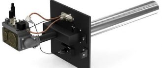
For EC fans
To regulate the operation of energy-saving fans with EC motors, EC controllers or control units for EC fans are used. To control such controller blocks, it is necessary to purchase a regulator with a 0-10V control signal.