A batch switch is the simplest type of device for turning off/on electricity. This is a switch, familiar from Soviet times at the entrance to the apartment in the switchboard. Often also used in electrical installations, control panels, where a manual control principle is required. For homes, the device is positioned as less modern, without the function of protecting wiring or auto-de-energizing during overloads. Nevertheless, packages fulfill their tasks, which is why they can still be found in electrical panels of houses. Replaced with modern and compact automatic circuit breakers (CBs) with a protection function.
Why do you need a packet switch: purpose
The device is used to control small load currents.
It is often used to disconnect electrical machines, power circuits, and loads due to switches assembled in one housing. The second name for a batch switch is a disk switch, which is used to switch the load between power supply circuits.
How it works: operating principle
The operator, who turns the handle, starts the work of the movable washers. The movement is transmitted to the contact group and opens or closes the circuit.
The packetizers have only two positions – on and off. If you choose the cam option, you can use the programming option; switching contacts in this case depends on the position of the switch.
Application area
- In electrical boxes and access panels - they control the load, turning it on and off. Some models have transparent windows to visually see the contacts.
- They are installed in control panels and substations to make it easier to take readings.
- It is actively used by drivers of electric power equipment (cranes, excavators). The speed and direction of work are controlled by this device.
What types of packages are there?
They are classified according to their degree of protection. And the purpose of this or that PV depends on this:
- Open. Designed for installation in dry, dust-free and inaccessible places. They do not tolerate high levels of humidity. As a rule, they are installed in iron boxes, shields and niches.
- Protected. They prevent not only accidental touches, but also objects from falling onto bare contacts. The housing is made of plastic and protects the bag from dust and moisture, so it can be installed outside the electrical panel.
- Sealed. Durable aluminum housing provides better protection against moisture. Such bags are installed not only in very damp rooms, but also in open areas.
Based on the type of fastening, bags are manufactured in 4 options:
- The fastener is located behind a 4 mm panel. Snaps into place with a front clip. The wire entry is at the rear.
- The fastener is located behind the 24 mm panel. It is also fixed with a front bracket, and the wires are connected from the back.
- The package switch is attached to the housing itself.
- The fastener is located in the cabinet, and is latched with a rear bracket. The wire entry is located at the front.
On a note! It is easier and more reliable to mount the connected package on the DIN rail into the distribution panel.
How are package switches and switches arranged?
The design assumes the presence of a switching mechanism and a group of contacts.
All of them are in the shell. The contact terminals extend from the housing and are shaped like knives. The spring connects and disconnects the contacts. The spring is controlled using a switch. By turning the handle, the spring begins to influence the mechanism. The washer and moving contacts rotate. The stop located in the cover blocks the movement of the washer. Plates made of fiber, and movable contacts are attached to them. As the material heats up, gas is released through the openings of the bag. At the same time, non-ionized air enters the housing, which extinguishes the arc.
Simplicity of design and ease of operation determine the purpose of the switch. The choice of model depends on the conditions in which the device will be used - at high humidity, in dry rooms, for shields.
Automatic backup
Sometimes they install a backup machine, but this is not necessary, especially when the line is further protected by an RCD+AV or RCBO. If you decide to install such a device, then you are guided by the standard rule: the optimal rating is less than that of the main device and more than that of group switches further down the line (for example, if there are RCD+AV combinations to protect the boiler, etc.). Example: the main device is 32 A and the backup device is 25 A, if the group devices are 20 A. If such a ratio is impossible, then at least the value should be no lower, that is, correspond to the input AB. In this case, the backup will have the role of a disconnecting device (during line repairs); in emergency conditions, it will snap off simultaneously with the main device.
Classification and labeling
Classification depends on various characteristics:
- Depending on the location of the cables, they are divided into front and rear connections.
- according to the degree of protection from external factors - open, protected, sealed devices.
- according to key design features - packet-cam, drum.
Despite the existing variety of switches, they all have common performance characteristics.
The spring mechanism can withstand 130 shifts. Wear-resistant models can withstand up to 200 switching operations. But the frequency of operation should not be more than 50 times per hour.
Marking allows you to determine the level of protection, type of placement, rated current. Otherwise, you can come across the following designations: “P” – switch, “P” – packet, “G” – sealed; 1-4 – specified number of poles; “N” – direction; "strength." (silumin) and “pl.” (plastic) – used to indicate the material of the case.
More modern analogues of the device
The old package switches have been replaced almost everywhere with automatic machines. This is logical, because the requirements for energy consumption and durability of devices have changed. Nowadays, RCDs (residual current devices), automatic and differential circuit breakers, and contactors are widely used.
Option #1: residual current device
The device is designed to prevent current leaks. It reacts to differential current, which contributes to overheating of electrical cables, which can lead to a short circuit and fire of the wiring. Leaks can also cause electric shock to a person.
The device cannot be considered a 100% analogue of a bagger, however, when combined with a circuit breaker, it performs even more functions
An RCD must be installed to avoid the risk of electric current leakage if it begins to pass by consumer devices. The device functions as a leak indicator, which simply turns off the electricity in case of problems.
The residual current device itself does not protect against overloads or short circuits. This is only possible if it is connected in combination with a circuit breaker.
Option #2: circuit breaker
These devices replaced the batch switch. They perform the same functions, but are more convenient to use, durable and wear-resistant.
Automatic switches can also be one-, two-, three-, four-pole. They differ in the type of drive (it can be manual, spring, motor), type of connection and other technical and operational characteristics.
A selective circuit breaker does not require additional power to make or open its contacts. The device is electro-mechanical and is designed to perform its functions in the best possible way.
Circuit breakers offered for sale are marked and classified in accordance with GOSTs 9098–78 and 14255. These documents establish requirements for the technical characteristics of devices.
Option #3: differential machine
This is a combined machine that simultaneously performs the functions of two devices - an RCD and a circuit breaker. The differential automatic machine perfectly replaces the packetizer, is suitable for household electrical networks and is successfully used in enterprises.
Differential circuit breaker is a “2 in 1” device: a circuit breaker and an RCD located in a common housing. It flawlessly copes with the tasks of both devices and at the same time is compact and easy to use.
The functional and design differences between the diffavtomat and the RCD are given here; we recommend that you familiarize yourself with the very useful information.
The differential circuit breaker prevents leaks, short circuits, and minimizes the risk of electric shock. The design of the device includes thermal and electromagnetic releases. The first prevents overloads in the network, and the second is needed to turn off the electric current in the event of a short circuit.
Option #4: contactor - a type of electromagnetic relay
The device is necessary for remote control of on/off modes of electrical circuits. Electromagnetic relays do not operate in the event of a short circuit and are designed for rated currents only. This is their main difference from circuit breakers.
The devices are characterized by exceptional electrical and mechanical wear resistance. They are installed in the mechanisms of elevators, vehicles, and used in enterprises
In modern residential buildings, outdated package switches are rarely installed. Almost everywhere it is practiced to install automatic circuit breakers or connect an RCD in combination with a circuit breaker. But there are cases when a good old bag can be indispensable, for example, if you need to turn off the current supply during electrical installation work.
Connection diagram
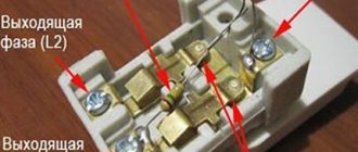
Compactness allows you to install a package switch in the panel. For this you need a DIN rail. If the model is old, you will even have to use self-tapping screws. Modern models provide other fastenings. The phase and zero from the electric brush are connected to the two input terminals of the package switch. Output terminals are connected to the machines in the brush.
When connecting, read the manufacturers' technical documentation.
It is not recommended to experiment blindly. On old domestic circuits, the phase is indicated in blue, and zero in red. Imported manufacturers may have different designations. There are many videos online that demonstrate the connection diagram.
Once every six months, the bags are cleaned and checked for functionality.
What to do first
You bought a certain number of wires from the network of a new house, completed the wiring, its ends are connected to a control panel that has not yet been built into the wall, and there are automatic machines nearby. Remember: it is better to install one automatic packetizer or RCD at the entrance to the electric meter. There is no such thing as too much protection. Next, make a plan for connecting the wires to the arranged packages.
It is advisable to relieve the network by dividing it into zones - with heavy loads and normal ones: kitchen, living room-bedroom, corridor-toilet, veranda-basement. You will get confused with packets; the instructions for them describe currents, loads, and wiring cross-sections. Methods of contact with terminals and so on.
When will replacement be required?
The service life depends on how the locking washer looks.
This is the main part of the switch; if it fails, the device requires replacement. Packet switches cannot be repaired. If damaged, immediate replacement is required. But you won’t have to debug the device throughout the entire period of operation.
Despite the decline in popularity of such models, manufacturers still delight with new developments. Each time the products are improved and shortcomings are eliminated.
And if package switches are less common in everyday life, then in production you simply cannot do without them. Compactness and ease of installation, resistance to damage, ease of maintenance are the main advantages of the package switch.
The short service life is the main disadvantage of the switch.
It is worth paying attention to the models: Legrand (France), Iek (Russia), ABB (Sweden, Switzerland). The products of these companies are characterized by reliability and quality.
Cable Requirements
You can already understand that not every cable is suitable for connecting such equipment. This is logical, since under heavy overloads it will simply burn out and can cause equipment failure or a fire. Therefore, when choosing a cable for an electric stove, you should rely on the following important characteristics:
- Rated voltage;
- material that serves as the basis for wire cores;
- cable section;
- ease of connection to the device.
If we take the rated voltage for devices of well-known brands, then its value must be exactly no less than that provided by the conventional electrical network where the device needs to be connected. Now let's say a little more about the described indicators.
Probably one of the most important aspects that will play a role is the material used to make the cable cores. It's best if they are copper. This metal itself can be soldered if necessary. And the copper power wire is more flexible than its aluminum counterpart. But the cost of a copper solution will be higher. If the choice falls on an aluminum analogue, then you need to understand that its installation should not be carried out in materials that burn. You can find out what the electrical wire is made of thanks to special markings on the product itself.
If we talk directly about numbers, then, as a rule, most solutions from well-known brands (Samsung or Electrolux) are designed for electricity consumption of just under 4 kW. For this reason, the safety margin of the wire needs to be selected based on power somewhere with a focus on this indicator.
To ensure that the device operates as safely as possible, you should also pay attention to the following points:
- If you need to lay the cord directly from the panel to the electric stove, a cord with a standard cross-section of 1.5 square meters is sufficient. mm.
- If other electrical appliances will be connected between the device and the panel, then you should have a cable with a cross-section of at least 2.5 square meters. mm. This option will provide the necessary reserve in case of connecting some other household appliances.
Another important parameter is the phase connection. It will depend on the number of cores in the cable. The wire can be 3 or 5 wires. The number of cores will depend on the power supply network in the room. And it can be either 1-phase or 3-phase. If the first option, then you will need to purchase a wire with three cores, and if the second - with five.
You should also find out whether the purchased equipment supports the type of connection that was selected. For example, stoves with a power of up to 5 kW are usually connected to a 1-phase network, while more powerful ones have a 2 or 3-phase connection. The type of cable that can be used will also be important, but more on that below.
Starting the motor in reverse
For individual equipment to function, it is necessary that the motor can rotate both left and right.
The connection diagram for this option contains two MPs, a push-button station or three separate keys - two starting ones “Forward”, “Back” and “Stop”.
To implement this option, another signal circuit is added to the circuit with one MP. It includes the SB3 key, MP KM2. The power part has also been slightly changed
From short circuit the power circuit is protected by normally closed contacts KM1.2, KM2.2.
The circuit is prepared for operation as follows:
- Turn on AB QF1.
- The power contacts of MP KM1, KM2 receive phases A, B, C.
- The phase that supplies the control circuit (A) through SF1 (signal circuit breaker) and the SB1 “Stop” key is supplied to contact 3 (keys SB2, SB3), contact 13NO (MP KM1, KM2).
Next, the circuit operates according to an algorithm depending on the direction of rotation of the motor.
Engine reverse control
Rotation begins when the SB2 key is activated. In this case, phase A is supplied through KM2.2 to the MP coil KM1. The starter starts turning on with the closing of the normally open contacts and the opening of the normally closed ones.
The closure of KM1.1 provokes self-catching, and the closing of the KM1 contacts is followed by the supply of phases A, B, C to identical contacts of the motor windings and it begins to rotate.
Before starting the motor in the opposite direction, it is necessary to stop the previously specified rotation using the “Stop” button. To twist in the opposite direction, you only need to use the KM2 starter to change the dislocation of some two supply phases
The action taken will disconnect the circuit, control phase A will no longer be supplied to the KM1 inductor, and the core with contacts will be restored to its original position by means of a return spring.
The contacts will disconnect and the voltage supply to the motor M will stop. The circuit will be in standby mode.
It is launched by pressing the SB3 button. Phase A through KM1.2 will go to KM2, MP, will work and through KM2.1 will be self-retaining.
Next, the MP, through contacts KM2, will swap the phases. As a result, the motor M will change the direction of rotation. At this time, connection KM2.2, located in the circuit supplying MP KM1, will disconnect, preventing KM1 from being turned on while KM2 is operating.
Power circuit operation
The responsibility for switching phases to redirect the rotation of the motor rests with the power circuit.
The white wire connects phase A to the left contact of MP KM1, then through the jumper it goes to the left contact of KM2. The starter outputs are also connected by a cross-jumper and then phase A of the motor is supplied to the first winding through KM1
When the contacts of MP KM1 are triggered, the first winding receives phase A, the second winding receives phase B, and the third receives phase C. In this case, the motor rotates to the left.
When KM2 is triggered, phases B and C are relocated. The first goes to the third winding, the second to the second. There are no changes in phase A. The engine will begin to rotate to the right.
Electrical panel for the meter and machines - choosing an installation location
Let's start with the simplest part - where to place the switchboard in the apartment? It is most convenient to place it near the front door in the hallway. In this case, you will not have to pull the power cable far from the site. The best height option is at the eye level of an adult. And it’s convenient to take meter readings and turn off the machines if necessary.
For those who support pushing everything under the ceiling, “for greater security, like they used to hang meters,” let’s say the following. Old electric meters with fuse plugs were simply mounted on the wall without boxes, and therefore were hung from the ceiling.
A modern electrical panel has a durable casing and is locked, so children will not get in unless you leave the key in a visible place.
When choosing a location for installing a panel in a private house or cottage, you need to consider where and how the cable from the overhead line or underground supply line is or will be installed. Data on external networks can be obtained from local energy sales.
Buy a ready-made one or assemble an electrical panel yourself
As they say in the old song “what progress has come”, you can buy a ready-made shield with a full filling or assemble a ready-made one. If your electrician suggests such a “proprietary” assembly design, then do not be alarmed. The panels are assembled by enterprises and electrical installation companies, including on order or for standard residential wiring projects.
The main point that needs to be clarified is whether your master has worked with ready-made shields before or this is his first experience. If he has installed a dozen or two such assemblies and knows their features, then feel free to agree. But if you are a “guinea pig” for the first experiment, refuse. It’s better to let him assemble it himself, with his own hands, the old fashioned way.
Device design
This design received its name due to its structure. Identical parts of communication elements are assembled on one long axis. The photo of the packet switch shows the detailed structure of this installation.
The housing is made of high-quality insulating material. There are additional holes on the surface for electrical contacts. There are arc suppression chambers here. In the center there is a movable washer, which is also made of high-quality insulation. It has legs made of electrodes. These several elements, which are located on the long axis, help to activate the mechanism.
The biscuits bag consists of an insulating body. On its surface there are moving and stationary parts of the contacts. Additional springs on the insulation rest against the center of the figured washer.