Most options for connecting one device to another will not require complex skills from the master, such as independently laying additional wires or installing grounding in an apartment where there is none. However, in this case, some restrictions are imposed on the operation of the connected sockets: certain types of electrical appliances cannot be connected to the network. To connect the outlet yourself, you need to understand the structure of the apartment's electrical wiring and be able to identify the functions of the wires located in the niche.
Installation sequence
There are no fundamental differences in connecting conventional and combined electrical fittings. For most modern interlocked electrical appliances, the fit size of the internal part of the unit, intended for hidden wiring, corresponds to the size of single sockets and switches.
The only thing that may be required when laying out a cable with a larger cross-section, which is necessary to connect three sockets at the same time, is punching a groove of a larger cross-section.
The approximate sequence of operations when connecting a combined unit is as follows:
- Markings are made for the laying of the wire (cable) indicating the installation locations of the mounting boxes into which the interlocked electrical fittings will be attached.
- A hole is drilled at the location where the box is installed using a drill bit installed in an electric drill.
- In the box it is necessary to break out the perforated plugs of the holes in the places where the cable is inserted.
- The stripped ends of the wire are placed inside the boxes.
- The boxes are fixed in the wall panel.
- After removing the cover from the socket block, connect the wires to its terminals.
- The block is installed inside the box and secured in it.
- To mask the installation gaps, a decorative panel is installed on top of the installed and connected socket-switch unit.
When choosing a specific model, there may be some installation features, however, the connection sequence does not differ from that described above.
Connection from a single-key unit
Connection diagram for a socket with a single-key switch
The most widely used units are electrical fittings in which one or more sockets are interlocked with a single-key switch.
In most models, several sockets have a single connection - a group of two terminal clamps for phase and zero, and the phase terminal has a jumper for one of the switch contacts.
The sequence of operations is as follows:
- From the apartment distribution panel to the distribution box, a two-core cable is supplied, supplying phase and zero.
- In the same box you need to insert three wires from the “socket-switch” block, and two wires from the lighting fixture.
- In the distribution box, the phase wire is connected to the wire coming from the socket terminal.
- The neutral wire from the lighting fixture is connected in the box to the “zero” from the distribution panel, and the second wire from the lamp is connected to the conductor connected to the free contact of the switch.
- If the socket in the block has a ground connection (“European standard”), then it is necessary to lay a separate wire to the pinching contact in the distribution box.
Connecting a multi-key switch will differ only in the number of conductors connecting the contacts of the switch to the lighting device.
Blocks with LED backlighting of circuits are technically no different from conventional interlocked electrical fittings. At the same time, the LED power supply circuit is built into the design of the device and does not require any additional connection.
In what cases may such actions be necessary?
- Sometimes additional consumers of electricity appear in the room, and we are forced to find a way to power them. At the same time, we cannot use existing sockets loaded with electrical appliances;
- One or more sockets in the room are broken. Sometimes the failed connection point was the only one, and in this case, one of the solutions would be to create an outlet from the switch.
Important! Wiring an outlet from a switch, although a procedure permitted by the rules, is still a temporary solution to the problem. Subsequently, this posting must be reduced to the original distribution.
Types of switches
Manufacturers produce a large number of different switches; they differ from each other in many ways. In order to understand, we will look at them in more detail.
Table 1. Types of switches according to the method of connecting wires.
| View | Description |
| With clamp and screws | To connect the contacts in such a device, a clamp is installed, which is secured with screws. Installation of this connection is complicated, but high-quality contact is obtained. Of course, over time the connection will become loose, then you will have to tighten the screws. It is believed that this connection method is suitable when there are aluminum wires. |
| Mechanisms with springs | This is a modern version of the screw clamp. Here, under the spring, there is a special plate that fixes the exposed wire. This results in a high-quality connection. However, this is a rather primitive installation method. The disadvantage of the design is that the wire must be clamped in accordance with the rules. Otherwise the device will be faulty. These switches are compatible with copper wiring. |
Table 2. Types of switches by installation method.
| Type | Description |
| Invoices | This is the common name for devices that are first placed on the wall and then fixed. They look less aesthetically pleasing because they stick out. Often such devices are used in the presence of external wiring. At the same time, the devices are distinguished by their functionality and ease of installation. |
| Built-in | An opening in the wall is prepared in advance for such switches. Because of this feature, installation is complicated, but in the end the device will look aesthetically pleasing. Only the outer panel can protrude slightly from the wall. Such devices are suitable for hidden wiring. |
Table 3. Types of switches by management method.
| View, illustration | Description |
| With keys | These devices consist of contacts that are located inside and a swing mechanism with a spring. The first version of such a device is a mechanism with a ball that moves when pressed. The second option is a spring-loaded frame; it also rolls from side to side. Such switches can have one or several keys. They are distinguished by long-term operation with proper installation. |
| Cord type | Such devices were at the peak of their popularity in 1975. Moreover, they are also installed on modern lamps of various types. So, a strong cord comes out of the body of the switch, which just needs to be pulled to turn the device on or off. This lace is fixed on a special lever, which interacts with the rotation block. |
| Sensory | The operation of these devices occurs without mechanical impact. In order to turn the switch on or off, you need to touch the panel located on the outside with your finger. The sensor element responds to touch and sends a signal to the electrical circuit. This signal is converted into a special command. |
| With remote control | Such a device assumes the ability to control the lighting device from a distance. This happens thanks to the presence of a special remote control. The switch in this case acts as a receiver. The remote control is a small plastic keychain. The operating distance will also depend on the materials from which the ceilings are made. However, the signal is received even at a distance of 18 meters. |
| With built-in sensor | Typically, these devices respond to certain changes in their surroundings. Most often, this is the movement of a massive object, which causes a signal to be sent to the controller. These are programmable switches. Therefore, the user can independently decide under what circumstances the device will turn on. |
Non-standard application
Some experts advise using a one-key switch with a socket instead of a standard socket - supplying the phase through a switch. This method is convenient for equipment without a shutdown button or quick de-energization of the equipment.
The disadvantage of the scheme is that it is compatible only with low-power consumers, which almost never happens in practice. None of the contacts are designed for high current, so the wiring heats up, melts and causes a fire.
The idea of combining a switch and socket appeared recently, but the devices quickly became popular for reasons of convenience and functionality. If the schemes are followed correctly, combined appliances will become an excellent interior solution, zone the space, and increase the number of power supply points.
Cost indicators of combined electrical fittings
Study BPA16-242B
The cost of interlocked sockets and switches depends on their functionality. Of course, a multi-key unit with several sockets will cost significantly more than one socket combined with a single-key switch.
Most people who have a little knowledge of electrical engineering choose any fittings not based on price, but on reliability, which can indirectly be determined by the brand (manufacturer).
At the same time, the purchase should be made either in company stores or from dealers of electrical engineering companies, who guarantee the impossibility of selling counterfeit products.
Today, electrical products bearing the trademark “Legrand” and “Schneider Electric” (France), “Lezard” and “Gira” (Germany), “Viko” (Turkey) and some others are quite in demand.
Let's consider the cost indicators of interlocked installation electrical fittings using the example of the French brand “Schneider Electric”:
- A two-key unit with one Euro socket “Etude BPA16-242B” costs about 300 rubles. This fitting allows you to connect electrical appliances with a power of up to 3.5 kilowatts to the outlet. A similar model in a waterproof version, the socket of which has a protective cover, can be purchased for 400-420 rubles.
- A single-key three-outlet power unit will cost 1,100 rubles. The high cost is due to the presence of a built-in filter.
- A single-key unit with one socket with a grounding switch costs less than 200 rubles.
Legrand products are slightly more expensive. Typically, all electrical fittings of this brand are equipped with decorative overlays. A single-key unit “Legrand Valena”, complemented by two European sockets, can be purchased for 650-655 rubles.
Combined devices
Combined type of device
The combined type of switches was not familiar to electricians until the mid-twentieth century. The current way to control light sources was a single-key switch. Two identical products were placed side by side. A little later, manufacturers released two-key switches for controlling individual groups of chandelier lamps.
A three-key switch combined with a socket appeared on the territory of the Russian Federation during the period of development of the construction of panel houses. The devices were intended to turn on lights in the kitchen, bathroom and bathroom.
The socket was installed in the bathroom for ease of use of a hairdryer and electric razor. After the popularization of washing machines, they began to be connected to a combi-appliance with or without grounding.
Double design for kitchen use
In modern high-rise buildings, double structures are used for kitchens, bathrooms and living spaces. The reason lies in European standards, according to which:
- switches are located at a height of 160 cm from the floor;
- sockets are installed at a height of 30-90 cm from the floor.
This connection allows you to place the switches at eye level for ease of use and furniture placement. Removing the socket allows you to conveniently turn off the lighting without changing the position of your hand.
Low-mounted socket groups in the bedroom are convenient in terms of masking wires. In the kitchen, they are placed above the work table and serve to illuminate the food preparation area and connect household appliances. In studio apartments, general and local light is used as a method of zoning space.
Combined devices are convenient for using numerous electrical appliances.
Installation of a single-key unit
First, the power is turned off. Before work, preparation is carried out: markings are made on the section of the wall for installation. At the marked points, holes are drilled with a crown, then a niche is made. The perforated elements for pulling the cable are removed from the installation box, then it is inserted into the hole made.
A socket with a single-key block is the simplest option. First of all, the parts that secure the decorative trim are removed from the device. First, unscrew the screw from the center of the socket, then remove the key using a screwdriver with a thin blade. If difficulties arise, then it is replaced with a knife. The plastic plate under the key is also removed. Then the socket and switch are freed from the housing. To do this, the side screws are loosened, but not completely unscrewed. The elements are rotated a little, then pulled out of the box.
Connecting the cable to the contacts
Before connecting an outlet with a switch, you need to figure out the number of wires required for the device. In our case (with grounding), four wires are required to connect this block to the network. Three of them will be incoming: ground, zero and phase. One is outgoing, through which power will go to the lighting device. If there is no grounding, then a three-wire cable is sufficient. Each additional key of the block implies an increase in the number of conductors per core.
If you purchased a ready-made device, then the socket with the switch is already connected by a phase conductor
You need to pay attention to this when assembling the unit yourself. Passage of neutral through the switch is prohibited
This is dangerous: both during operation and when servicing devices (replacing light sources).
The work occurs according to the following scenario: connecting the phase, protection, neutral and signal core.
Phase connection
The phase wire is connected to the contact on which the jumper is located. This solution allows you to power both elements of the unit at once - the socket and the switch. To simplify the work, it is better to use a four-core cable.
In this case, it is easy to understand using color coding. Any conductor can become a phase, except blue (zero) and yellow-green (ground). The two remaining wires will be phase conductors: their usual colors are white, brown, red. One of them is intended for the incoming, the second for the conductor going to the lighting fixture. It is called a signal.
Grounding
If the parting provides a contact or grounding bracket, then a yellow-green (solid yellow or green) conductor is connected to it
In this case, it is necessary to “wrap it up” that such a precaution is needed only by the socket, the switch does not need grounding
When work is carried out in a private house, grounding must be provided without fail.
In the old buildings this was not taken into account, so there is only one alternative - protective grounding. If the operation is performed correctly and the RCD or breaker is installed, there will be no danger
Zero connection
In this case, use a blue (blue) wire. It is connected to the only socket contact that remains free. It doesn’t go anywhere else, because there is no need for it to switch the switch.
There is another opinion on how to connect a socket with a switch
Some craftsmen believe that it is not very important which conductor goes to the switch (zero or phase), because the light will go out in any case. Misconception is dangerous
When such a lamp is turned off, the voltage remains on it. If the technician touches the cartridge, he may receive an electric shock.
Another negative point is energy-saving lamps, which often blink when the switch is open. Their circuit contains a capacitor that accumulates voltage coming from the phase wire. When the capacitance limit is reached, the device discharges a discharge to the emitter.
Signal (outgoing) conductor
This element is connected last. For ease of installation, the core should have a slightly longer length. The outgoing conductor is attached to the remaining contact of the switch. Its standard location is the lower part of the combined block.
After fixing the last conductor, the operation called “How to connect a socket with a switch” can be considered almost complete. The last stages are assembling the device and securing it in its rightful place.
How to connect
The simplest connection method is parallel, but the ability to use the outlet will be limited. Firstly, the voltage will be very weak, although sufficient to use chargers and automatic air fresheners. More demanding devices will not work as required. Secondly, you can use such an outlet only if the network is open. Due to these limitations, connecting in this way is not cost-effective and not entirely correct.
A switch is a communication that breaks the circuit and there is no need to connect a “zero” to it. If we talk about the outlet, it powers most devices, so it needs a “zero”. By connecting these two devices in parallel, you can violate safety regulations and violate all regulations, which can lead to negative consequences. However, as a temporary measure, this method exists.
The main condition for correct connection is that after connection it will not be possible to use the light device. If it is not needed in a given room, then replacing it with an outlet will not be difficult. The first thing you need to do is connect the outlet to the wires going to the switch. The place where the light fixture was previously located must be closed. The main thing is not to forget about the insulation of the “ground” located next to the lamp.
The most suitable option would be a two-key switch, then you can simply connect the socket to one of the bundles of contacts in the device. Then, in the chandelier, you should remove the lamp and install a jumper in its place to connect the two wires.
The final steps will be to replace the two-key switch with a standard one-key switch, and connect the socket itself to a free bundle of contacts. This can be done in a short time and solve a number of repair and planning ideas.
Advantages and disadvantages
The great demand for combined devices is determined not only by the desire to place additional outlets in the room. Combined models have a number of advantages:
- Reducing the number of wires. When placed separately, two power wires are supplied to each socket. Each switch has two conductors: one coming from the electrical panel and one going to the lamp. Only two wires from the panel are suitable for the combined device, and exactly as many wires go out as there are keys on the switch.
- Reduced labor costs when organizing hidden wiring in the room. When using separately located sockets and switches, a cable is laid to each device, for placement of which grooves are made in the walls. This is quite labor-intensive work. The ability to place all cables in one groove significantly reduces the amount of construction work and simplifies the installation of electrical wiring.
- Ease of use. People who live for a long time in houses with a European arrangement of switches get used to this height of placement of devices. For them, the appearance of additional sockets next to the usual switches increases comfort when controlling lighting and using household electrical appliances.
It is a mistake to assume that combined models do not have disadvantages. There are a number of reasons why many people refuse such devices. Here are some of the cons:
- Price. Combined blocks usually cost more than individual elements. If one component fails, the entire structure will have to be changed, which will increase costs.
- Increased load on power wires. Voltage is supplied to the device through two wires, which will carry the load from both the lamps of the lamp and the device plugged into the outlet. This should be taken into account when calculating the cross-section of the supply wires, otherwise there is a risk of overheating and a fire.
- Location restrictions. The conventional switch is easily accessible from any position. The plug and cord of an electrical appliance, especially massive ones, in some cases can make it difficult to use the switch key. In addition, a cable hanging next to a switch does not always look aesthetically pleasing.
Some useful tips
- When choosing a model of a combined socket with a switch, give preference to a product that has two teeth on its legs. Such blocks are fixed more securely and firmly in the wall.
- If there is a need to connect several household appliances at the same time, use an outlet block. Most often it is used in kitchens where a refrigerator, hood, dishwasher, electric kettle, and TV are constantly running.
- When you buy socket boxes, choose models whose internal walls are ribbed. When installing the switching device, the spreading legs will cling more securely.
You are now familiar with all the disadvantages and advantages of such a combined block. Do you know how to install and connect such a switching device? Decide for yourself whether you need this type of socket with a switch or not. Let us repeat once again, for utility rooms this is a very convenient option; for a living room it is better to use a separate option.
Connecting the cable
Connect to an existing outlet like this:
- the end of the new cable is cut to a convenient length;
- free the ends of the cores from insulation to a length of 1 cm. There is a special tool for this operation - a stripper (also known as a crimper), which eliminates the possibility of damage to the core. In its absence, the insulation is carefully cut off with an ordinary knife, trying not to damage the core;
- the bare ends of the strands are bent into loops and lightly squeezed with pliers;
- Having pressed the spacer antennae, remove the inner part of the socket and loosen the screws on the phase and zero terminals. The grounding conductor is completely unscrewed;
- the power cores of the new cable are inserted into the terminals and the screws are tightened. Now each terminal has two wires - from the power cable and from the jumper for the new socket. The colors of the insulation on the cores in each terminal are the same.
Grounding is connected differently. For it, connecting with a cable is unacceptable due to low reliability: if the contact in one of the sockets burns out, all subsequent ones will be left without grounding. According to the PUE, it is necessary to maintain the continuity of the conductor by making a branch for each socket.
Do this:
- a crimp sleeve is put on the unscrewed grounding conductor of the supply cable and two more conductors are inserted into it: from the jumper cable and a short section - a branch for the existing socket;
- press the sleeve with press pliers;
- put a heat-shrinkable tube on it and heat the latter with a hot air gun or lighter (insulation);
- Screw the branch to the grounding contact of the existing outlet.
Do the same when connecting each subsequent socket of the cable. The existing outlet is being assembled
It is important to make sure that the limiter on its inside (a rectangular metal plate) does not squeeze the jumper wire. If this is discovered, a cutout is made for the wire in the socket box, and if necessary, the hole in the wall is deepened
Basic mistakes
Brown wire - phase, blue - neutral, yellow-green - ground
Installing an additional outlet is usually not difficult. But beginners can make the following mistakes:
Wrong choice of wire cross-section. You need a cable of the same thickness as the main outlet. Using a wire made of a different material. Connecting two different wires causes additional difficulties, and the contact itself is less reliable. Violation of the order of connecting wires
Particular attention should be paid to the grounding conductor. If it is not available in the house (especially in old buildings), it is better to purchase sockets without ground. Unreliable contact
You need to familiarize yourself in advance with the existing methods of creating a contact and practice connecting on spare sections of wires. Installing wires diagonally. Standards only allow vertical cable routing.
There is also a risk of buying a model that is not suitable in design. This is not a critical error from a technical point of view, but can disrupt the overall concept of the room. Therefore, when purchasing, it is recommended to select the color of the product, its shape and size in advance. Manufacturers of electrical products offer a wide range of products; any buyer will find a product that suits the style.
Selecting a wiring method
Work is carried out according to the same principle
- Cable thickness. The cross section of the child coincides with the parent.
- Design. Does not affect functionality, matches the interior, depends on the wishes of the owner.
- Contact connection system. Depends on how many contacts are located on the household appliance - two or three.
- In the first case, zero and phase are connected to different contacts.
- When using three wires - phase, neutral and grounding, which is attached to the fastening screw located on the device body, after first removing the cover from it.
- Grounding. If it is present in the first socket, it is also mounted on subsequent ones, taking into account the requirements of the PEU, which indicate the use of a solid cable.
Hidden
- Grooves are cut into the wall - grooves, and the cable is laid in them.
- Cover with cement or gypsum mortar.
- Then they move on to finishing work.
Attention: To install a socket from an existing one, find out whether it is possible to cut a groove, a groove, drill a recess for the socket box, and only then proceed with the connection.
Installation procedure
Work plan
- Turn off the electricity and de-energize the room where repair work is being carried out. The tester makes sure that everything is done correctly.
- Remove the cover from the main outlet.
- Remove the device by loosening the retaining contacts.
- Connect the cable to the new point.
- Make sure that the cable is not crushed by the limiter; if necessary, break off a piece of the wall or socket box, adjusting it to the size of the wire.
- Reinstall the socket.
- Drill a hole in the decorative cover for the cable.
- Screw on the lid.
- Run the wiring down to the baseboard, guide it to the desired point, attaching it to the wall with staples at a distance of 30–40 cm from each other.
Hiding options
- With the external method, it is screwed to the baseboard or left as a carrier. The wire is hidden in a cable channel glued to the wall or attached between the socket cover and the baseboard.
- A cable installed for a long time is hidden under a layer of plaster. To do this, make a groove, lay the wiring, then cover it with plaster.
- If the wall is covered with wallpaper, they are cut along the cable laying line, after wetting it. Then, carefully, so as not to tear, move the edges of the wallpaper apart and make a groove for the cable. After laying, they are also covered with cement mortar, and the wallpaper is glued back.
Preparatory work
No matter how many keys your switch has (one, two or three), the preparatory work will be the same.
To begin with, you need to install a general distribution box and a mounting box for the switching device in the room; it is also called a socket box:
- If the walls in your room are made of PVC, plasterboard sheets, wood or MDF panels, install a special bit with serrated edges on a drill and make a hole. Insert the mounting box into it and fix it to the wall using self-tapping screws.
- For concrete or brick walls, make a hole using a hammer drill or drill with an attachment that works on concrete surfaces. But in this case, the mounting boxes must also be fixed using gypsum or alabaster mortar
As a rule, the installation of holes is carried out simultaneously with the laying of grooves. This is done purely for aesthetic reasons; there is a lot of dirt from such construction work, and it’s better to spray it once and clean it up. Grooves are grooves in the wall surface into which connecting wires will then be laid. They can be done using various tools:
- Hammer and chisel. This is an old ancestral method, its advantage is the complete absence of costs for purchasing tools (every man has a hammer and chisel). The disadvantage of this method of gating is that it takes a lot of time and effort.
- Bulgarian. This tool is often called the worst of the best. It’s convenient that grooves can be made quickly and without much effort. But it is from the grinder that there is a lot of noise and dust, and besides, it is not possible to make grooves of the same depth along the entire length, and it is almost impossible to work with the grinder in the corners of the room. So choose such a power tool as a last resort.
- Hammer. All you need is to purchase a special attachment for it - a strober or a spatula. In all other respects there are no shortcomings, it’s fast, convenient, the grooves are more or less even.
- Wall chaser. This is the ideal tool for this type of work. Works efficiently, safely and quickly. The grooves are smooth, there is no dust, since the wall chaser is connected to a construction vacuum cleaner. They are comfortable to work with and the tool does not make much noise. The only drawback is the high price. But there are services where you can rent a wall chaser.
Briefly about gating walls using the tools listed above is described in this video:
It is necessary to lay two-core wires into the grooves and fix them with cement or alabaster mortar.
So, the preparatory work is completed, the boxes are mounted, the wires are laid, and you can connect the light bulbs and switch.
Schemes for connecting sockets to the electrical network
First connection diagram
To connect with your own hands, you need to know the wiring diagrams for the sockets you will use to do this. Let's start with a connection diagram to a single-phase network, which does not have a ground loop.
Socket connection diagram
Meaning of digital designations:
1 – general safety coupled machine.
2 – automatic switch that disconnects the phase on the line to which the sockets will be connected.
3 – zero bus.
4 – distribution switching boxes. They must be located exactly above the sockets so that the vertical outlet section falls down. Each outlet must have its own connection box.
5 – the cable of hidden or open wiring is conventionally shown.
The main thing is to correctly place the phase on the socket on the left, and the zero on the right. This is an electrician's rule that must be followed.
Second connection diagram
The second scheme - on the one hand, these are also single sockets, but of a different “F” type, with a connection to the ground loop.
Connection diagram for single sockets to a single-phase network with a ground loop
Of the new digital designations in this diagram, only 6 are the connection bus for grounding (PE) wires. Shown in green.
However, another option for wiring is also possible, which is often used, for example, in utility rooms, especially with an open type of wiring. In this case, the ground loop runs from below, along the floor along the perimeter of the walls. And a separate wire rises from it to the socket. And the eyeliner itself on top is the usual phase and zero. The switching on the socket terminals does not change in any way.
If the connection is to a network without a ground loop, then everything is much simpler. In this case, the sockets are connected with a cable. That is, the phase wire approaches the first, and is connected from it to the second by a jumper. Further, from the second jumper goes to the third. The neutral contacts of sockets are also switched in a similar way.
Where is it used?
Let's consider a situation where it is necessary to connect some new lamp or sconce from an outlet through a switch. There are cases when the renovation has already been completed, but there is a need for additional lighting. In order not to pull wires from the junction box and not to ditch all the walls, the additional switch and lighting fixture are connected from an outlet that is located nearby.
The socket represents two potentials, one of which we will take for the switch (phase), the second we will extend to the light bulb (zero).
This option is widely used in kitchens. On the working wall (also called an apron) there are several sockets for connecting many household kitchen appliances. It is advisable to place a switch in one frame, with the help of which the lighting of the kitchen table will be turned on and off.
Keep in mind! Such a switching scheme will be rational only if the lamp is located in close proximity to the socket. If the lighting fixture is located far away, make all connections through the junction box.
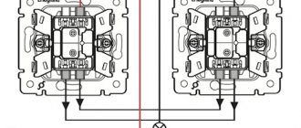
Wiring a socket from a double switch
If in the first case we received a fully functional socket, but at the same time, in fact, we lost the lighting in the room, then in the case of a paired switch everything happens differently. After all, this way we can equip an extra outlet while maintaining lighting in the room.
The main task in this operation is to redistribute the purpose of one of the three wires that is connected to the switch. We will do this, as in the upper case, using a junction box. The task is to assign this third wire the role of the neutral conductor. In total, the task is divided into several stages:
- De-energizing the network, dismantling the double switch, preparing a place for the socket and installing it;
- We go to the distribution box and reconnect one of the wires coming from the switch side to the common neutral conductor. The corresponding wire going directly to the lighting device is disconnected and isolated from the general network;
- When working with the socket, we connect one core to the created core wire, and the second to the phase wire, which is laid to the switch;
- After installing the double switch, the conductors are connected to the terminals. The device continues to perform its function, but in this case it turns into a single switch.
Remember the importance of following safety rules!
Whether you're working on an outlet or a light switch, remember that we're talking about electricity. Therefore, it is necessary to work with it, observing all safety rules, as well as having special equipment. If you are not confident in your abilities, then it is best to entrust the process to professionals.
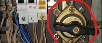
Important! All wiring work must be carried out only when the electricity is turned off. As a rule, there is an automatic machine at the entrance or even in the apartment, where this can be done either for one room or for the entire apartment as a whole.
Switch
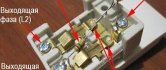
The switch consists of two contact groups (input and output). Its main task is to close or open a ready-made electrical circuit to supply voltage to the lighting device. Remember, this switching device always works only for phase interruption, it does not need zero. Only phase wires should be connected to the switch: one from the supply network (to the incoming contact), the second from the lamp (to the outgoing contact).
Screw the red wire connector onto the black wire from the outlet, the black power wire that goes back to the switch, and the black wire from the dangling cord, connecting all three together. Wrap the black pigtail wire around one of the screws on the right side of the existing light switch that you set aside earlier. Wrap the remaining black wire around the remaining screw on the right side of the light switch. Carefully insert two sets of both black and bare copper wire into the back of the electrical switch and reconnect the switch to the top and bottom of the box.
Step by step process
The algorithm for such work will look like this:
- De-energize your workplace by turning off the circuit breaker that directly supplies this room. If there is no panel with such a group division of rooms, then turn off the common input machine for the apartment. Use an indicator screwdriver to check that there is no voltage at the workplace.
- Near the socket, make a hole for the switch and fix the socket box in it. You will also need to make a small groove between the socket and the switch where the jumper wire will be laid.
- Install the lighting fixture in the desired location. Here you can see for yourself how it is more convenient for you to do it. You can also carefully punch a groove up to the lamp, lay a two-core wire in it, and then cover it with wallpaper. Or you can lay the wire in a plastic box, it also looks nice and neat.
- Remove the cover from the socket and pull out its contact part from the socket box. If you yourself installed this switching device in the past and observed the color designation of the wires, then the terminal to which the blue wire is connected will be zero, and the terminal with the white (red or brown) wire connected is a phase. In sockets with protective grounding there is also an additional terminal in the middle where the grounding conductor is connected; it is usually made in yellow-green color. If you do not know exactly where the phase and zero are, this must be determined by applying voltage to the disassembled socket and touching the terminals with an indicator screwdriver. The luminous window on the screwdriver means that you are touching the phase wire, respectively, the second wire will be neutral.
- Connect a wire core to the phase terminal of the socket, the second end of which should be connected to the input contact of the switch. Lay this wire in the groove between the holes and fix it with a solution.
- Connect a wire to the neutral terminal of the socket that will go to the neutral contact of the lamp socket. If the housing of the lighting device must be grounded, then the grounding conductor can also be pulled from the corresponding terminal of the socket, only in this case it will be necessary to lay a three-core wire to the lamp.
- A wire core is connected to the output contact of the switch, which will be the phase of the lamp.
- This completes the switching actions. All that remains is to fix the working parts of the switching devices in the socket boxes and put the protective frames on top. The last key is attached to the switch and the assembled circuit is tested in action.
- Apply voltage by turning on the input circuit breaker. Insert the plug of any household appliance into the socket, it should work. Now press the switch key, the lamp in the lamp should light up.
This version discusses in detail how to install a switch with one key. In the same way, you can install a device with two or three keys, only a separate wire must go from each output contact of the switch to a certain group of lamps.
We looked at how you can connect a switch from an already installed outlet. Remember that this option in a household electrical network is the exception rather than the norm and is used in cases of extreme necessity.
Connection diagrams
Several cables can come into the junction box.
Firstly, this is a three-wire power cable from the lighting circuit breaker installed in the electrical panel. Secondly, a 4-wire cable goes down to the three-key switch, which you have already connected from below.
Well, then there may be options. If you have one chandelier with 3, 6, 9 bulbs, then you can connect it with one single five or 4-core VVGnG-Ls cable with a cross-section of 1.5 mm2.
If you have three independent lamps, in different parts of the room or house, then you will have to run a separate 3-core cable to each of them. Let's consider the last option in more detail.
What tools do we need?
The list of tools is not very large: an indicator screwdriver, a socket (read more about purchases below), pliers (the presence of a rubber handle is extremely important), as well as a suitable wire. At the same time, for safety reasons, it is better to purchase rubberized gloves. Well, if the work is carried out without turning off the current (which should be avoided in every possible way), then a rubber mat under your feet will also become a critical factor.
Manufacturing companies
Often the choice of a particular switch with a socket is determined by the attractiveness of the design. For example, the Spanish company produces antique-style models. German products are distinguished by modern, sophisticated design. French electrics are successfully integrated into the surrounding interior: both vertical and horizontal modifications are made. Perhaps the widest selection of products is presented. The product line of this Swiss company also includes products with LED backlighting.
Among Russian manufacturers, Kuntsevo-Electro can be distinguished. The company produces several models of three-key switches:
- BELLA BKVR-039 (there is a socket without a grounding contact);
- BELLA BKVR-212 (with indicator light);
- BELLA BKVR-036 (the model is equipped with a European socket and protective curtains).
Combined unit Bella BKVR-033 and BKVR-054
The specified switches operate in 220 V networks with a rated current of 10 A. Models are also produced in Russia for a rated current of 16 A with grounding. For example, NPO Elektrotekhnika produces models BZVRzk-S and BZVRzksh-S.