Installing a Legrand light switch: device features
The mechanism consists of five elements. For correct installation, you need to understand how each part works.
- frame;
- frame;
- terminals;
- buttons and contacts;
- the base on which all elements are located. It is this that allows you to securely mount the product on the wall or attach it to the mounting box.
The French manufacturer makes the base from galvanized steel. This material is not subject to deformation, therefore it provides the most reliable fastening. There are four mounting screws on the back side. Installation of the Legrand light switch is possible in a mounting box of any size.
The shape of the fastenings is universal. It allows you to adjust the position of the device - rotate it in any direction and center it.
For convenient connection of wires, automatic terminals are provided. Connecting cables is as simplified as possible: just strip the wires and insert them into the terminals. The latter are often located at an angle of 35°.
The manufacturer took care of the user. He provided a marker on the back panel. Based on it, it is easier to understand how much insulation needs to be removed.
Rotary
About 50 - 60 years ago, rotary switches were still actively used in the construction of houses, but recently they have been used only in “antique” design projects or in creating interiors in country, loft, and Provence styles. As a rule, they are produced only for outdoor installation and are used in conjunction with open wiring. Switched by turning the lever 90°.
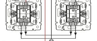
Schematic diagram of the operation of a pass-through switch.
Let's immediately figure out how they work in principle.
Unlike conventional switches, which have a fixed position of the power key and simply break the circuit, pass-through switches can be switched on with any position of the key, because they switch from one of two lines to another, which is very similar to switching a railroad switch (see the diagram above ) and allows us to control the inclusion of artificial light from different places.
The phase comes to the first pass-through switch, and from the second it goes to the lamp, and both of them must be connected to each other with a two-core electrical cable or wire. But, as a rule, no one connects them directly, but three separate wires from each are inserted into a junction box and two of them are simply connected in pairs to each other.
When connecting additionally, if necessary, a third, fourth, etc., the circuit essentially does not change, but their connection differs from the first two, which had one input contact and two output ones. They will need to have two input and 2 output wires connected, allowing them to be used to cross-switch between two lines.
The operating principle of the third pass-through switch (when purchasing, pay attention to whether it has the ability to work as a cross switch) is that when switching, it connects the first contact at the input to the second at the output, and the second contact at the input to the first at the output. To connect it, you actually need to connect it to two other pass-through switches with a 2-wire cable, but no one does this, but run the 4-wire cable into a junction box and make the connection there according to the diagram
Similarly, you can add a fourth to the circuit, which will be located between the third and second or first switch.
We have looked at the theoretical part, let's now look at specific practical schemes.
Markings on devices
Sometimes you can see symbols on the front of the switch. They indicate the area of application of the device.
Device with marking of on and off positions.
Conventional light switches equipped with keys may be labeled I and O to indicate the on and off positions.
Device with a key symbol.
Also, conventional devices that work only to open or close an electrical circuit can be marked with a key symbol.
Push-button switch with bell symbol.
Push-button switches without fixing in one of the positions can be used both as bell buttons and as switches in a lighting system assembled on the basis of pulse relays. Such devices are marked in the form of a bell (bell).
Pass-through switch of overhead design with bidirectional arrows.
Pass-through switch with staircase symbol for indoor installation.
Pass-through type devices can be marked with symbols in the form of a bidirectional arrow or in the form of a flight of stairs.
Some manufacturers have keys with space for inserting a character. But in general, there is no single standard for marking devices, just as there is no obligation to put symbols on the front. Therefore, many manufacturers, both little-known and world leaders in the electrical engineering market, often neglect the application of markings.
Connection diagram for the pass-through switch wires in the distribution box
Scheme without grounding conductor
Now the most important thing is to correctly assemble the circuit in the junction box. Four 3-core cables should go into it:
power cable from lighting circuit breaker
cable to switch No. 1
cable to switch No. 2
cable for lamp or chandelier
When connecting wires, it is most convenient to orient them by color. If you use a three-core VVG cable, then it has two most common color markings:
or second option:
To choose a more correct phasing in the second case, follow the tips from the article “Color marking of wires. GOSTs and rules."
1Assembly begins with neutral conductors.
Connect the neutral conductor from the cable of the input machine and the neutral going to the lamp at one point using the terminals of the car.
2Next you need to connect all the grounding conductors if you have a grounding conductor.
Similar to the neutral wires, you combine the “ground” from the input cable with the “ground” of the outgoing cable for lighting.
This wire is connected to the lamp body.
3 All that remains is to connect the phase conductors correctly and without errors.
The phase from the input cable must be connected to the phase of the outgoing wire to the common terminal of the pass-through switch No. 1.
And connect the common wire from pass-through switch No. 2 with a separate wago clamp to the phase conductor of the lighting cable.
Having completed all these connections, all that remains is to connect the secondary (outgoing) conductors from switch No. 1 and No. 2 to each other
And it doesn’t matter at all how you connect them
You can even mix up the colors. But it’s better to stick to the colors so as not to get confused in the future.
At this point, you can consider the circuit fully assembled, apply voltage and check the lighting.
The basic connection rules in this diagram that you need to remember:
the phase from the machine must go to the common conductor of the first switch
and the same phase should go from the common conductor of the second switch to the light bulb
the remaining two auxiliary conductors are connected to each other in the junction box
zero and ground are supplied directly to the light bulbs without switches
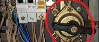
Modular load switch or input circuit breaker? 4 advantages of use.
Surely many of you have used circuit breakers. There were no problems turning the lights on and off using such switches. But you should know that, first of all, circuit breakers were created not for frequent switching operations, but to protect electrical wiring and pantographs from overcurrents.
The role of an ordinary switch, that is, breaking the circuit, is a secondary task of the circuit breaker.
And if you abuse frequent shutdowns using automatic machines, especially without disconnecting the load from the sockets, the contacts inside the automatic machine gradually burn out.
Features of the Valena series
The most popular switches are those united by the Valena series. They are intended for indoor use and are mounted by installing them in a mounting box.
Polycarbonate is used to produce the frame and key cover of each device. They are mainly available in white, ivory, aluminum and titanium.
As for technical capabilities, most devices in this series are designed for a current of 10 amperes. There are also models that are designed for 16 amps.
The Valena series switches from Legrand have a simple connection diagram and can be one- or two-key, push-button, louver, card, and can also have an indication, backlight or dimmer. The category also includes pass-through switches.
Models have housing protection IP20 or IP44. The latest marking indicates that the switch can be used in rooms with high humidity, since it is protected from water.
Galea Life and Gealine series
Legrand Galea Life series
As for the Galea Life line, it is called elite. This is because it combines expensive appliances. They are intended for indoor use and are mounted in socket boxes. The degree of protection is IP20.
The views are the same as in the previous series.
The main feature of this line from Legrand lies in the external design of each switch. It is created thanks to the original frames and keys.
They are made of wood, metal, corian (artificial stone), durable duroplast, and are also covered with leather. Each material can be dyed a different color and can have a different pattern.
As you can see, the equipment included in this line is ideal for emphasizing sophisticated interior styles.
switch Legrand Celiane
Very interesting is the Gealine category, which combines original shaped devices for turning on lamps. These Legrand switches (some with a dimmer) are characterized by a combination of square frames and rounded keys.
Thanks to the proper use of colors, such devices look very beautiful. They may have different textures. These textures are made not only from plastic, but also from wood, porcelain, glass and genuine leather. Of course, thanks to such materials the price is quite high.
For those people who want to purchase an economical option for switches, you should pay attention to the Etika series. Of course, the frame and surface of the keys are made of plastic
Also distinguishing features include a method that determines how you can connect a one or two-key Legrand switch. It involves using a special nut to secure the wires. As you can see, models in this series do not have terminal blocks.
Outdoor switches Quteo and Plexo
Legrand Quteo series of surface mounted switches
It is also worth paying attention to such series as Quteo and Plexo. The lines described above include devices that need to be installed in a mounting box
However, we know that it is often necessary to use switches that are mounted on the wall surface.
This is exactly what the Quteo line models are. Their special feature is that the body is made of impact-resistant ABS plastic. The housing can have IP20 and IP44 protection.
Series of protected switches Legrand Plexo
Models assume the presence of one or two keys. As for the color design, it involves the use of one of three colors. So, the switch can resemble a tree, it can be white, or it can look like ivory.
The switches in the Plexo line are somewhat similar. They are also mounted on the wall surface. However, their main feature is the presence of IP55 and IP66 protection. In other words, they are intended for use in wet areas.
They are mainly used in industrial premises, restaurants, schools, utility rooms, courtyards, and garages.
Video connection of Legrand switch:
We make holes for sockets in concrete and tiles ourselves Schneider Electric - high-quality sockets from the world leader Installing a socket or switch in a plasterboard wall, brief instructions Installation height of sockets in a modern apartment
Rope
The operating principle of this switch is similar to a push-button switch: by pulling the string until it clicks, you close the contacts. Pull a second time and open. This type of switch is primarily used in wall sconces and sometimes for turning on exhaust fans.
Rope switches are not only used for decorative purposes; they have a number of practical advantages. For example, a dangling cord is easy to find by touch in the dark, and such switches are also suitable for families with small children; the child can easily reach it and be able to turn the light on and off independently.
Connection diagram
Depending on the application and purpose, feed-through devices can be connected in several different ways:
- Installation of key-type pass-through devices for controlling one light source from two places.
- Connecting a single-key switch to control a group of lighting lamps from three or more places.
- Installation of a two-key switch to control two independent light sources with one double device.
Before describing the connection diagram for a pass-through switch, let’s remember how a standard one works.
Connection diagram for a standard switch
Connection diagram for a standard switch: N – phase zero, which is connected directly to the lamp; L – the energized phase passing through the switch and ensuring the ignition of the light by connecting the contacts in the circuit. Switching off, accordingly, occurs when the voltage is interrupted. Distribution box is the junction of the main cable with the “branches” of lighting and current distribution.
Thus, a regular switch allows you to turn on/extinguish the light from one control point from one place according to the principle of interrupting/connecting current.
The pass-through switch has a slightly different principle of operation: it is equipped with three contacts (and a double switch of this type has six) and operates on the principle of switching from one contact of the circuit to another.
Connection diagram for a Legrand pass-through switch: N – the neutral wire is connected directly to the lamp; L – the energized phase is supplied to the lamp, alternately passing through the switches and, unlike a standard switch, the supply/disconnection of light occurs not due to the closure/connector of the circuit contact, but due to their switching.
Connecting a two-key pass-through switch. A two-key switch is a common type of pass-through devices. As a rule, it is used to turn on/off lights in two different rooms from one place. Often used in apartment buildings.
Essentially, these are two independent single-key devices connected in one housing. The phases of the devices are combined and operate on the “switching” principle. This means that the moment one key is supplied with power, the other interrupts the circuit and is disconnected.
Legrand two-key pass-through devices are equipped with two independent groups of contacts, due to which the keys work independently of each other - when you press one of them, the switch occurs from the upper lines to the lower ones, and the first do not have a final output, and the second are connected to another similar switch.
It follows that these devices have two independent groups of contacts: right and left. Now that we have clarified this point, it will be easier to understand how to connect this type of device.
The most popular models of this type of device are the legrand etika and valena series. Below you can see the connection diagram for a two-key pass-through switch.
Connection diagram for a two-key pass-through switch
Legrand Etika/Valena two-key pass-through switch. Connection diagram: the contacts of the right group are connected to each other by a jumper; the phase wire is connected to the second of them. The contacts of the left group supply current to two lighting devices independent of each other, and they should not be connected to each other.
Remote
These are switches that are activated by a signal from the remote control. There are also combined models: for example, a touch switch with a remote control. Remote switches are not very common because they are quite expensive. In addition, remote controls tend to get lost.
But there are also advantages. Firstly, with remote switches you don’t have to damage the walls: you just need to arm yourself with self-tapping screws or double-sided tape and secure the switches in the right places. And no problems with fixed wiring. Secondly, you can turn light bulbs on and off from anywhere in your apartment or house and feel like the master of light.
Installation of sockets and switches
Sockets and switches are installed after wallpapering or painting the walls. Installing sockets is one of the last jobs performed during a renovation.
It goes without saying that the electricity should be turned off. That is, turn it off exactly in the room in which work will be done to install sockets and switches. This can be done by finding the appropriate machine in the electrical panel. If you don’t know which machine turns off the electricity supply to the room, you can determine this experimentally by turning off the machines one by one and listening to where the cries of “TV doesn’t work!” or “turn on the bathroom light!” This method will allow you to accurately determine the connection of each of the machines with a specific area of the apartment. If there is no one else in the apartment except you, then you will have to do it differently.
Turn off all machines. Expose the wires in the socket boxes and switch in the room where the installation needs to be done. Now, turn on the machines one by one and, armed with an indicator screwdriver, check which machine, when you turn on, the indicator on the screwdriver lights up when it touches the phase wire.
Push-button
The principle of operation of a push-button switch is similar to a key switch: you press the button - it locks and closes the contact. Pressing it again opens the contact. Often available with LED backlighting. Such switches should not be confused with ordinary electrical buttons, for example, on a bell: such buttons make a contact only if they are held by hand.
Push-button switches will easily fit into the interior of any room, despite their slightly non-standard appearance. They cost a little more than their keyboard counterparts. But they will serve you faithfully for a long time.
How to connect two-key models
It should be said that the procedure for connecting such devices is almost no different from single-key types.
The only difference will be the number of devices, and accordingly the power cable will be routed to two devices.
Let's take a closer look at this process:
- First of all, one supply phase wire and two outgoing lines are wired to the distribution boards.
- Then the phases and neutrals are wired from the electrical panels.
- Finally, the zeros and phases of the devices are connected.