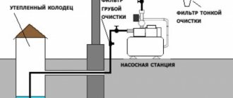
Water at their summer cottage is required not only by the owners to comply with sanitary and hygienic standards. It is necessary for watering plants, caring for the territory and pets, refreshing and swimming in the hot summer. Agree that it is difficult to lift the entire required volume from the source manually with buckets.
However, there is a way to alleviate the difficult fate of summer residents - this is a homemade water pump. Even if you don’t have the funds to buy pumping equipment, you can become the happy owner of a useful technical device. To build it, sometimes literally just the power of thought is enough.
We have collected and systematized for you valuable information about making almost free homemade products. The models presented for consideration were tested in practice and deservedly received recognition from the owners. A thorough description of the manufacturing technology is supplemented with diagrams, photographs and video materials.
Design #2 - manual pump with direct spout
A very simple device for pumping water from a barrel or a shaft well. The advantages of this design: speed of assembly, low cost.
Required parts:
- PVC pipe d.50mm – 1 pc.;
- PVC coupling d.50mm – 1 piece;
- PPR pipe d.24mm – 1 pc.;
- PPR branch no. 24 – 1 piece;
- PVC plug d.50mm – 2 pcs.;
- piece of rubber, diameter 50mm, thickness 3-4mm – 1 piece;
- check valve 15mm – 1 piece;
- empty silicone bottle 330ml – 1 piece;
- tightening screw clamp – 1 piece;
- screw-nut or rivet – 1 piece;
- union nut no. 15 – 1 pc.
We begin the assembly of the entire structure with the manufacture of a check valve.
Construction of a check valve. We prepare a check valve from a Ø 50mm plug. We drill several holes around the perimeter of the plug Ø 5-6mm. In the center we drill a hole of suitable diameter for a screw-nut pair or rivet.
On the inside of the plug we place a rubber disk Ø 50mm. The disc should not rub against the walls of the plug, but should cover all drilled holes. We tighten it in the center with a screw-nut or rivet; a screw will not work. If difficulties arise with materials or manufacturing, you can replace it with a factory-ready check valve.
What a factory-made check valve used to operate a pumping station is is described in detail in the article we recommend.
Preparing the pump sleeve. The length of the sleeve should be commensurate with the depth of the well or container with water. We cut the PVC sewer pipe Ø 50mm to the required length, from the narrow end. We insert the newly made valve into the pipe socket. For reliability, we fasten it on both sides with self-tapping screws.
For the second end we prepare a plug with a pre-drilled hole Ø 25mm. This hole in the plug is made according to the diameter of the PPR pipe Ø 24. Great precision is not required, the plug serves as a sliding support.
Piston assembly procedure. Cut off the spout of an empty silicone container. Next, you need to heat the balloon and insert the sleeve into the PVC so that the diameter of the balloon exactly matches the diameter of the sleeve. Place the silicone can on the valve from the reverse side of the arrow (the arrow on the check valve shows the direction of water movement).
We cut off the excess balloon. We secure it with a union nut no. 15.
Pump rod design. The length of the rod should be 50-60 cm greater than the length of the sleeve. You need to heat one end of the rod and insert a check valve. The arrow on the check valve should point towards the inside of the stem. Until the pipe has completely cooled down, we tighten it with a screw clamp.
Final assembly of the pump. We insert the rod into the sleeve and attach a plug (sliding support) through the coupling on top. To top it off, we attach a 24mm PPR bend to the end of the rod pipe. All you have to do is connect the hose and you can pump water.
The pipe material can be any, and the cross-section is not necessarily round. It is important to select the appropriate piston for the liner
The outlet serves as a support for the hand. For convenience, you can take a tee and plug one side of it.
Homemade pump for overflowing water
The simplest mini-pump for overflowing or pumping water can be assembled in just 10 minutes. At the same time, you will not only not spend money on the manufacture of this device, but will also solve such an important problem as recycling household waste. This water pump, which is essentially a check valve to which a tube with an outlet is connected, will be especially useful in cases where you have to frequently draw water from a large container into buckets.
So, to make a simple water pump with your own hands, you will need the following consumables:
- several necks cut off from plastic bottles with caps screwed onto them;
- a piece of hose of the required length;
- tube that will serve as a rod.
A suitable check valve can be used to pump water using this method.
A homemade water pump is made from the above materials according to the following algorithm.
- It is necessary to remove a thin gasket from the cork of a plastic bottle and cut it in a circle, reducing its diameter by about 2 mm and leaving a 3 mm wide segment intact.
- A hole with a diameter of 8–10 mm is drilled in the center of the plug itself, through which the pumped water will flow into the rod tube.
- The gasket is inserted into the cork, into which the neck cut off from the bottle is screwed. Thus, the neck screwed into the cork will press only the untouched segment of the gasket, leaving the rest of it movable.
- A rod tube is connected to the resulting valve, which will act as a nipple.
- To increase the water capture surface, a “skirt” is put on the stem with the valve, also made from a bottle cut to the required length.
- They complete the manufacture of a mini water pump with their own hands by connecting a piece of hose to the back side of the rod-tube.
To activate the water pump, you need to immerse its intake part in a container of water and, holding the rod, make several reciprocating movements. As a result, the liquid medium from the container will begin to flow into the hose by gravity if there is a level difference. To stop the process of overflowing water from the container, it is necessary to raise the end of the hose above the level of the valve or simply remove such a valve from the aquatic environment.
Design #3 - manual pump with side spout
The previous design has one, but significant drawback. The spout moves with the stem. This design is not much more complicated, but much more convenient.
The sleeve needs to be improved. Add a 50mm PVC tee to the design with a 35 degree bend. The tee must be inserted into the upper part of the sleeve. In the rod, near the piston, we drill several large-diameter holes, the main thing is not to overdo it and not to disturb the rigidity of the entire structure.
The piston moving upward pushes the liquid into the outlet pipe. The top cover serves as a support for the piston rod
Now water will begin to pour into the space between the rod and the sleeve. When the piston moves upward, water will begin to flow into the spout.
Grinder in the fecal pump
Separately, it is worth highlighting devices equipped with a built-in grinder, which is capable of grinding large solid particles. Improved models come in both external and submersible types.
The chopper is a structural element equipped with stainless steel cutting blades
Externally, such units look like storage tanks, inside of which pumps with a chopper are installed. Once in the storage tank, the dense particles are crushed by knives within a few seconds, from where they then enter the septic tank. The scope of application of fecal pumps equipped with a grinder is much wider. In addition to arranging an autonomous sewer system, they are used for:
Equipped with a shredder, the submersible unit easily copes with household waste and easily processes paper and plastic, algae and branches.
The grinder grinds undissolved grains into a homogeneous mass, which flows freely through drainage pipes of even small diameter
Main parameters of surface pumps with grinders:
On sale you can find models that are designed with a float chamber with automatic shut-off. This helps protect the device from dry operation. At the moment when the sewage reaches a certain level, the engine will simply turn off.
Source
Design #4 - piston well pump
This pump design is suitable for wells no more than 8 meters. The operating principle is based on the vacuum created by the piston inside the cylinder. A useful homemade product can be an excellent alternative to factory-made pumping equipment and will help solve the problems of water extraction for servicing a summer cottage.
In such pumps, the top cover is either absent or has a slot-like hole, since the rod is rigidly connected to the handle
Necessary materials:
- metal pipe, diameter 100mm, length 1m;
- rubber;
- piston;
- two valves.
The performance of the pump directly depends on the tightness of the entire structure.
You will find a detailed description of the manufacturing process of a piston pump for use in a summer cottage in one of the popular articles on our website.
Step #1: Assembly of the unit sleeve
To make a pump sleeve, you need to pay attention to the inner surface; it must be even and smooth. A good option would be a liner from a truck engine.
From below, a steel bottom needs to be welded to the sleeve along the diameter of the well head. Either a reed valve or a factory valve is installed in the center of the bottom.
A cover is made for the top of the sleeve, although this part is more aesthetic, you can do without it. It is necessary to pay attention to the fact that the hole for the piston rod is made slot-like.
Step #2: Construction of the Pump Piston
For the piston you need to take 2 metal disks. Between them lay not very thick rubber 1 cm, slightly larger in diameter than the disks. Next, we tighten the disks with bolts.
As a result, the rubber disk will be clamped and a sandwich of metal and rubber should be obtained. The idea is to create a rubber rim along the edge of the piston, which will form the necessary piston-liner seal.
All that remains is to install the valve and weld the eye for the stem.
Step #3. Making a petal valve from rubber
The reed valve consists of a rubber disc of not very thick thickness. The disc size should be larger than the inlet holes. A hole is drilled in the center of the rubber. Through this hole and a pressure washer, the rubber disk is secured over the inlet holes.
When sucked, the edges of the rubber rise and water begins to flow. During the reverse stroke, clamping pressure is created: the rubber reliably blocks the inlet holes.
Step #4: Final Assembly and Installation
It is advisable to cut a thread at the head of the well and at the bottom of the pump sleeve. The thread will allow the pump to be easily removed for maintenance and will make the installation sealed.
We install the top cover and attach the handle to the rod. For comfortable work, the end of the handle can be wrapped with electrical tape or rope, laying turn to turn.
If the pump does not pump water, it is necessary to eliminate all leaks, including in connection with the well head (+)
The limitation on the depth of the well is due to the theoretical impossibility of creating a vacuum of more than 1 atmosphere. If the well is deeper, you will have to modify the pump to a deep pump.
Creation of an airlift
Pumping water from reservoirs and underground sources can be organized without the help of standard pumping equipment. To do this you will need an original device called an airlift. To make such a simple but quite effective water pump with your own hands, you will need two pipes of different diameters, one of which will supply compressed air, and the second will pump out water, and a regular air compressor.
Operating principle of an airlift pump
The operating principle of the airlift, which was invented 200 years ago, is as follows. If you place two tubes in the water column, one of which will supply compressed air, this will lead to the formation of a mixture of liquid and bubbles. Such a mixture, having a lower density than water, will begin to rise up the second tube.
To see how such a water pump works, you can conduct a simple experiment by placing two tubes in a bottle of water, one of which is connected to an aquarium compressor powered by a low-power motor. When the compressor is turned on, water will begin to pour out of the second tube. The efficiency of such a water pump, usually not exceeding 70%, directly depends on several parameters - air flow, immersion depth and the total height to which the pumped water must be raised.
Design #5 - deep piston pump
The difference from a conventional piston pump is that the pump sleeve must be installed at the depth of the well. In this case, the length of the rod is more than 10 meters.
The sleeve of such a pump can serve as a wellbore, and the role of a spring can be played by a suspended load (+)
There are two ways to solve this problem:
- Make the rod from a lighter material, for example, aluminum pipe.
- Make a rod from a chain.
The second option requires some explanation. In this case, the rod is not rigid. The bottom of the liner is connected to the bottom of the piston by a return spring.
Purpose of manual models
A mechanical pump serves to supply water from any depth of a water source to the surface under pressure and is activated by physical force by pressing the handle. The device is characterized by low productivity compared to expensive electrical systems, so it is used when water consumption is low and there is no light.
Operating a well pump is most beneficial for summer residents. In private permanent residences with a regular power supply, a manual mechanism is needed as an addition to the automatic one, for example, in the event of a power failure or breakdown of the main system. In garden houses for occasional use, manual devices play the main role of water supply.
Design #6 - American or spiral type
The spiral pump uses the energy of the river flow. To operate, the minimum requirements must be met: depth - at least 30cm, flow speed - at least 1.5 m/s.
Option 1
Necessary materials:
- flexible hose d.50mm;
- several clamps according to the diameter of the hose;
- intake - PVC pipe 150mm;
- wheel;
- pipe reducer.
The main difficulty in such a pump is the pipe reducer. This can be found in decommissioned sewer trucks or obtained from factory equipment.
For greater efficiency, an impeller is attached to the pump
The flexible hose is attached to the wheel in a spiral using clamps. An intake made of PVC pipe 150mm is connected to one end. The second end of the hose is put on the pipe reducer.
Water is taken in by the water intake and moves in a spiral, creating the necessary pressure in the system. The lifting height depends on the flow speed and the immersion depth of the intake.
Option 2
Necessary materials:
- flexible hose d.12mm (5);
- plastic barrel d.50cm, length 90cm (7);
- polystyrene foam (4);
- impeller (3);
- sleeve coupling (2);
We cut an intake hole in the bottom of the barrel. Inside the barrel, it is necessary to lay the hose tightly in a spiral and connect it to the sleeve coupling.
Inside the barrel, the hose is laid tightly, pressed against the walls with a strip. The barrel can be metal with foam floats
To impart buoyancy, foam floats must be glued inside the barrel. Finally, screw on the impeller.
For this design option, the drain hose must be 25 mm. in diameter.
Manufacturing of Scroll Hydraulic Pump
For a dacha or a private house, in the immediate vicinity of which a river flows, you can make your own water pump, which looks very similar to a carousel (you can see the principle of its operation in a video on the Internet). The basis of the design of such a pump is a wheel with blades, driven into rotation by a moving river flow. The pumping unit in this device is a spiral made of a plastic pipe with a diameter of 50–75 mm and fixed to a wheel with blades using clamps.
Spiral hydraulic pump
The pipe spiral branch pipe, located on the outer contour of this design, is equipped with an intake bucket, which is made from a pipe of a larger diameter - 150 mm. The internal pipe of the spiral design is connected to a pipe reducer, which is located at the level of the axis of the wheel with blades and is securely fixed to a fixed base.
Pipe reducer is a key component of a volute pump
The maximum height to which such a homemade water pump can lift the pumped liquid medium will depend on the distance covered by the intake bucket of this device under water. The principle of operation of the water pump in question is based on the fact that at the moment the intake bucket is immersed in water, a closed system is formed in the spiral pipeline, consisting of sections of the liquid medium and air cavities, as a result of which the pumped liquid medium moves to the center of the spiral and enters the pipe reducer.
The cost of such a pumping installation, the manufacture of which will require certain knowledge and skills, will depend on how much the consumables and technical devices used in its design will cost you.
With the help of such original pumping equipment, you can organize complete watering of a summer cottage or personal plot in the summer, without using an electric pump for these purposes. This will save energy.
Design #7 - wave energy pump
As the name suggests, such pumps use wave energy. Of course, the waves on the lakes are not that big, but the pump works around the clock and is capable of pumping up to 20 cubic meters per day.
Option 1
Necessary materials:
- float;
- corrugated pipe;
- two valves;
- mounting mast.
The float is a pipe, a log, selected depending on the rigidity of the corrugated pipe, experimentally.
Corrugated pipe can be made of plastic or metal. The weight of the log must be selected experimentally
Two valves operating in the same direction are mounted in a corrugated pipe.
As the float moves downwards, the corrugated pipe stretches, resulting in water intake. When the float moves up, the corrugation contracts and pushes the water up. Therefore, the float must be quite heavy and large.
The entire structure is rigidly attached to the mast.
Option 2
This design differs from the first option in that the corrugated pipe is replaced by a brake chamber. This diaphragm-based scheme is very often used in simple DIY water pumps. Such a pump is quite versatile and can receive energy from wind, water, steam, and sun.
The brake chamber should be disassembled and only two holes left for the valves.
Instead of homemade valves, you can use ready-made plumbing valves. The washers must be of sufficient diameter so that the diaphragm does not tear (+)
Manufacturing suitable valves is a separate task.
Necessary materials:
- copper or brass tube;
- balls of slightly larger diameter - 2 pcs.;
- spring;
- copper strip or rod;
- rubber.
For the inlet valve, cut off the tube and drill it out so that the ball sits tightly on the tube. It is necessary to ensure that the ball does not allow water to pass through. To prevent the ball from falling out, solder a wire or strip on top.
The design of the exhaust valve differs from the intake valve in the presence of a spring. The spring must be installed between the ball and the copper strip.
We cut out a diaphragm from rubber to the size of the brake chamber. To drive the diaphragm, you need to drill a hole in the center and stretch the pin. We insert the valves from the bottom of the brake chamber. For sealing, you can use epoxy glue.
It is better to find non-metal balls for valves, so they will not be subject to corrosion.
Option 3
Based on the design of the two previous options, you can think about building a more advanced model.
It is advisable to choose a log that is dry and not resinous, so it will be lighter, pay attention to the absence of cracks
For this pump it is necessary to drive four stakes (1) into the bottom of the reservoir. Then make a float from a log. You need to make cuts in the log so that it does not rotate when swinging on the waves.
For durability, it is recommended to treat the log with a hot mixture of kerosene and drying oil. It must be done carefully, processed in a water bath: there should be no open flame.
The log travel limiters (3) and (4) are nailed in such a way that the log does not damage the pump rod (5) during maximum movement.
Wave pump
This design operates using wave energy and is capable of pumping water from a nearby body of water.
The main working part of the pump is a hollow cylinder in the form of an accordion. By contracting and stretching, the accordion changes its internal volume. One end of the corrugated pipe is connected to a log in the water, and the other to a holder on a pile that is driven into the bottom. On both sides the accordion has valves installed in bushings. When waves hit, the log begins to rise and fall, thereby transmitting oscillatory movements to the corrugation, compressing and decompressing it. If you pour water into it, the valves will start working and the pump will pump water.
If a corrugated pipe with a diameter of 50-60 mm is used, then the log should weigh 60-80 kg. To prevent the log from breaking the lift when high waves occur, a limiter should be attached to the pile. A bolt is passed through it and secured in the log. The head of the bolt should be under the cover plate, so that the log will rotate freely in different directions and will not break the pile if an unwanted torque occurs.
Important! If you have problems finding a corrugated pipe, then there is a wave pump design that works without it. Instead of corrugations, rubber ring diaphragms are used, connected in series into a single package.
Annular diaphragms are tightened with metal rings along the edges, inside and outside. The inner rings are made of metal and holes are made in them. A cord is attached between the rings, which will limit excessive stretching of the pump. Valves are also installed at the top and bottom of the pump.
As the log moves upward, the membrane package stretches, the bottom valve opens, and the pump begins to fill with water. As the log descends, the bag contracts, the bottom valve closes, and the top valve opens. Water is squeezed out through it.
Design #8 - device from a washing machine
Often, parts or even entire units from old things remain on the farm. You can remove a centrifugal pump from a washing machine that is no longer needed. This pump is perfect for pumping water from a depth of up to 2 meters.
Necessary materials:
- centrifugal pump from a washing machine;
- petal valve from a washing machine or homemade one;
- plug, bottle stopper;
- hose;
- preferably an isolation transformer.
If you use a ready-made valve from a washing machine, it needs to be modified. One hole needs to be plugged, for example using a bottle cap.
Excess pump holes must be plugged. If the case is metal, grounding is required
We connect the petal valve to the hose and lower it into a pit or well. Connect the second end of the hose to the pump. For the system to start working, it is necessary to fill the hose with the valve and the pump itself with water. All that remains is to connect the transformer, and the pump is ready for use.
Diaphragm pump
A diaphragm pump is made at home from a brake chamber from a truck, for example, from a MAZ-200.
A diaphragm pump is manufactured as follows.
- The camera is disassembled and all holes on the base (1) are sealed. The bolt holes do not need to be sealed.
- Holes for the inlet and outlet valves are drilled at the bottom of the base.
- The membrane (4) is made from a car inner tube and is secured using a brass rod with two brass washers. The diaphragm is glued around the perimeter to the body and additionally pressed with bolts.
- The pump is assembled according to the drawing above.
Design #9 - water pump from compressor
If you have already drilled a well and have an air compressor, do not rush to purchase a water pump. It will be successfully replaced by a structurally simple airlift device.
Necessary materials:
- spout pipe 20-30mm;
- air pipe 10-20mm;
The operating principle of the pump is very simple. It is necessary to drill a hole in the spout pipe and place them closer to the bottom. The hole should be 2-2.5 times larger in diameter than the air pipe. All that remains is to insert the air pipe and apply air pressure.
One of the most efficient and simple pumps, does not clog and can be assembled in 5 minutes
The efficiency of such a pump depends on the height of the water level, the depth of the reservoir, and the compressor power (performance). The efficiency is about 70%.
What tools and materials are needed for the job?
To make a homemade concrete pump, you will need to prepare everything you need:
- A sheet of whatman paper, pencils, a ruler, a compass to create a diagram.
- Iron sheet 5 mm thick.
- Screwdriver, wrenches, bolts.
- Electrical engine.
- Reduction gear.
- Lathe.
- Pipes for moving the solution.
- Steel for piston and valves. It will be more convenient if the pieces are round in shape.
- The welded frame is the basis of the structure.
Having prepared the necessary materials, you can make a mortar pump with your own hands.
Design #10 - gear water machine
The heart of this design is gear pumps for pumping oil from agricultural or truck equipment. The power steering power plant from KrAZ has similar characteristics.
Unit characteristics:
- pump working volume - 32 cm3;
- maximum pressure - 2.1 Atm;
- operating speed - 2400 rpm;
- maximum permissible rotation speed – 3600 rpm;
- nominal pumped volume – 72 l/min.
If possible, a motor from a washing machine is connected to such a pump. The motor of household appliances has a number of advantages: it runs on a single-phase 220V network and has a starting system (capacitor).
Gear mechanisms can be left- or right-handed, you need to pay attention to the direction of the arrow on the body
Pulleys and a belt may be required to obtain the required RPM. The advantage of a gear pump is that the gears are able to create the necessary suction force even without first filling it with water.
The only note: after operating the pump, to prevent corrosion of the steel gears, it is necessary to let the pump run idle for about 20 minutes.
DIY pump assembly guide
The pipe for the future pump cylinder must be carefully sanded from the inside, and holes must be cut in two opposite walls and short pipes for the valves must be welded. The piston head is turned on a lathe according to the dimensions of the hydraulic cup chamber in the drawing, brought and ground until it completely matches the internal diameter (the tolerance should not exceed ±0.1 mm). After this, valves are inserted into the pipes, tightened and adjusted with screws.
Drive assembly instructions:
- Attach the three-phase motor to the wheelbase or welded frame.
- Install a connecting coupling on the rotor shaft and connect the reduction mechanical gearbox through it.
- At the outlet, mount the crank and connecting rod attached to the piston head.
The finished mechanism is covered with a protective stainless steel casing. It is not easy to weld seams on it, so it is better to use bending technology to the maximum. It would not be a mistake to make the body from ordinary sheet iron, but to protect it from atmospheric influences it should be treated with an anti-corrosion metal primer and painted.
Manual
You can use a homemade concrete pump based on standard instructions for factory-assembled units. At the site, it is connected to two pipelines: the first connects to the bunker in which the solution is located, the second leads directly to the installation site. Installation of the supply path is the most difficult, especially if it is necessary to pump the mixture from bottom to top. It is better to immediately prepare a schematic drawing where you can determine the number of bends and connections. Their number should be reduced to the minimum possible, but without fanaticism. Give preference to elements without straight or sharp corners - it’s better to have a little more of them, but the concrete pipeline should be flat.
You also need to think about reliable fastening of the sleeve so that the heavy compound supplied under pressure with shocks does not tear it out. Metal trusses or scaffolding are suitable for this purpose. And for safety, the vertical part of the concrete pipeline should be located no closer than 9-10 m from the pump itself. A single-seat needle valve is also installed in the riser pipe - it will not allow the solution to reverse in the event of an emergency stop.
Since you have to work with thick mixtures, liquid cement laitance is first poured into the system. It plays the role of a kind of lubricant, allows you to avoid overloads when turning on the engine and prevents the formation of traffic jams in the tract. It is not recommended to do a dry test run.
The solution itself also has special requirements:
1. The size of large aggregates is tied to the internal diameter of the pipelines. The maximum fraction values cannot exceed 0.3d for crushed stone and 0.4d for gravel.
2. The mobility of the mixture must correspond to class P2, otherwise the solution may separate into components in the pump chamber. In the case of liquid concrete, water will be forced through the valve faster than heavy fractions.
3. It is worth checking the draft of the cone of the test portion in advance - ideally it should be from 40 to 120 mm.
During the pouring of the monolith, the risk of water hammer should be avoided. If you haven't welded the pressure gauge, you'll have to act on a whim. Here it is important to gradually increase the flow at the start-up stage until the operation stabilizes, and before turning off the unit, lower it. A sudden increase in pressure due to a change in flow rate can lead to valve failure.
After concreting, the system must be washed according to the instructions to remove residues. To do this, you can buy special balls of a diameter suitable for the pipeline; you will also need warm water and a compressor. Here it is important to catch the moment when the heated liquid needs to be poured into the bunker. It should be fed into the chamber immediately after the last batch of solution so that an air “pocket” does not form, but at the same time the water does not spoil the concrete itself.
Design #11 - pump from a bicycle wheel
Productive pump based on two wheels.
Necessary materials:
- PVC sewer pipes and outlets;
- bicycle wheel;
- nylon rope;
- small pulley;
- several pistons;
- mounting rod.
The operating principle of this pump is similar to that of a dragline.
First you need to build a sleeve from a sewer pipe that will be immersed in water. A drain is placed on the top of the sleeve through which water will flow. Next, install a small pulley on the bottom (a wheel rim from a wheelbarrow will do) and a bicycle wheel on top.
We attach a series of pistons along the entire length of the rope, first passing them through the sleeve. The rope should go around the pulley and the bicycle wheel.
The device is very effective, especially if you use a bicycle drive. It will be much easier to twist your legs.
By rotating the bicycle wheel, each piston on the rope captures water and, like an elevator, lifts it upward. The water column pours into the outlet.
Less popular manual modifications
In addition to piston models, which have proven themselves well in factory and homemade versions, other devices are also used.
They are less productive, but interesting from the point of view of design and operating principle.
Image gallery
Photo from
Bike pump
Wooden model with flexible stem
Membrane type device
Structure from a sleeve and a wheel
There are factory models that are not practical to make yourself. For example, equipment based on an impeller. Such devices are used in the industrial sector; they are not very convenient for the garden.
In addition, buying a compact metal device that looks like a can twister will cost no more than making it yourself.
None of the considered homemade pump designs suits you? Then we recommend that you look at more homemade options, the production of which we discussed in the next article.
Design #12 - “homemade” for a small stream
This pump can operate on an ultra-low amount of energy. Of course it’s good if there is a river or lake. But what to do if the river becomes very shallow in the summer? A swing type pump will help.
Such a pump allows you to use very small amounts of energy from a small stream.
The main part of the structure is two buckets rigidly connected to each other through blocks (4). It is necessary to make a drainage system from the stream from galvanized steel (3). In order to reduce wear, a piece of plastic is placed under it. The drainage system is rigidly connected by a leash to a rope (5).
Leash 6 is made of rigid wire and the length is calculated so that the drainage system moves to the desired angle
The entire system must be adjusted so that when one bucket is filled, the drainage moves to the second bucket. The energy of the buckets is transmitted through the crank (8) to the pump (10).
Types of fecal equipment
Unlike traditional analogues, which are vulnerable to various types of blockages, fecal equipment can easily cope with wastewater containing solid particles.
The main purpose of a septic tank pump is to pump wastewater
Depending on the installation method and design solution, there are three main types of fecal pumps: surface, submersible and semi-submersible.
Surface-type equipment is used for pumping water from local treatment facilities. They are compact and low cost.
Surface-type devices are capable of pumping out liquid whose inclusion sizes do not exceed 5 mm
Surface pumps are good because they can be placed at a considerable distance from the well (up to 9 meters). In this case, the pump itself remains on the surface, and only the suction pipe is immersed in the drains.
Manufacturers design devices differently. Surface models can be a full-fledged station operating in automatic mode, or a compact unit operating in manual mode.
Water pumps for septic tanks are divided into two groups:
The operation of most devices of this type is based on centrifugal force. But still, the so-called vortex devices are most in demand. Although they work only at shallow depths, they are famous for their greater power with minimal noise during operation.
If you focus on the type of engine, then there are gasoline, electric and diesel devices
A surface pump can only be installed permanently indoors. If there is no suitable room near the septic tank, experts recommend making a pit or caisson near the tank, into which to place the unit.
Submersible models are designed to pump out household waste containing large long-fiber impurities from storage tanks of autonomous sewers.
Submersible models are able to operate uninterruptedly in aggressive environments
Submersible pumping equipment is characterized by high power, which can reach 40 kW, and the ability to pump dense impurities with fractions up to 4 cm in size. Such a device cannot become clogged, since its flow channels are quite wide. The equipment is made of chemically resistant materials: cast iron, stainless steel.
The main difference between models of this type is the presence of a special float, thanks to which the engine remains above the surface of the water.
Semi-submersible pumps are used for pumping mainly small holes
An electric motor is used as a drive in semi-submersible models. They are characterized by an improved cooling system. The steel body and mechanical end seal reliably protect the device from moisture and destruction.
A significant disadvantage of submersible devices is the small diameter of the flow channels. This significantly limits the possibility of using them when pumping liquids with solid inclusions whose diameter exceeds 15 mm.
Design #13 - Shukhov wick pump
The Russian inventor Shukhov became famous for many buildings, including the radio tower in Moscow. Below we will discuss another of his inventions - a water pump.
Pulleys are made composite. The depth of the groove should be slightly less than the swollen rope
The pump uses a special rope to operate. This rope consists of woven cotton threads with a total thickness of 5-6 mm, enclosed in a sheath. The thread is passed through the pulleys.
When movement occurs, the rope gets wet and wraps around the pulleys. The pulley (5) with the help of a spring (4) presses the rope against the pulley (3) with force. The squeezed water flows into the tray (7). Figure “c” shows sections of pulleys (3) and (5), respectively.
To operate the entire system, an electric motor of only 5-10 watts is required. Typically, such engines have 1500 rpm.
To reduce speed and increase force, you can use a worm gear, shown in figure “c”. It is quite possible to make it by hand. To do this, you need to find a suitable gear and make a worm from wire. Small forces on the shaft allow manufacturing inaccuracies.
With your own hands you can assemble not only a pump that pumps water for domestic needs, but also a device that can be successfully used in landscaping a site. The following article will present successful options for homemade fountain pumps.
What types of concrete pump designs exist?
Depending on the type of drive, concrete pumps can be hydraulic or mechanical. According to the design, pistonless and piston ones are poured. Depending on the method of movement, concrete pumps are either stationary or mobile. Despite the apparent diversity, today two types of concrete pumps are used in construction: piston (with hydraulic drive) and rotary (with mechanical drive).
In a rotary unit, the mixture is supplied by rollers equipped with the rotor housing: during the process of rotation, they press on the supply hose and the concrete is thrown out from there. But it is very difficult to make such a concrete pump yourself, since the design of the rotary type is complex, so usually piston units are assembled with your own hands.
The piston installation includes three main parts:
- Piston – powers the cylinder
- Cylinder - the part responsible for taking the mixture from the hopper and pumping it
- Drive – usually choose hydraulic or electromechanical
Single-piston units are most often used, since double-piston units require a complex design. Operation of two-piston units is carried out thanks to an electric or diesel engine, which converts hydraulic energy into mechanical energy.
Needle well and tube well, features of arrangement and use
Tube well and Abyssinian are varieties of the classic well with differences in the arrangement of the trunk. Instead of rings, a tubular source shaft is formed from steel pipes, and an Abyssinian well is a needle-shaped well made from small-diameter steel pipes. The water intake is drilled to a depth of 15 m. Wells of this type cannot always be installed at the level of aquiferous sand, and groundwater cannot be used as drinking water.
The Abyssinian well is an improved type of tube well. Despite the shallow depth, there is a chance to get fairly clean water: high water and precipitation do not penetrate into the source. One of the main advantages is the low cost of arrangement and ease of implementation. An Abyssinian well can be made without the involvement of specialists.
The Abyssinian needle well can be used to collect drinking water for one home
The depth of the source ranges from 8 to 15 m. The first aquifer layer of sand lies at this depth. The end of the casing pipe is installed at the boundary between the layers of loam and sand. The main difficulty is to find a place where there will definitely be water at a shallow depth. Usually they are guided by the presence and depth of neighboring water intakes. If the areas are located at the same height, there is a high probability that the water layer occupies a large area.
An igloo well is constructed exclusively in soft soils: clay, loam, clay with layers of sand, quicksand. Such wells cannot be drilled in rocky soil: if a needle hits a boulder, all the work will have to be redone.
Small diameter drive pipe is not designed to pass through rocky soil
Water can be used after testing. Usually the quality of the water is acceptable, and if a filter system is installed, it can be used for cooking. The service life of a well does not exceed 10–12 years. The flow rate is subject to seasonal fluctuations, up to 1.5 m3. The amount of water is enough for 1 – 2 water points.
Surface water intakes are plugged using the impact-rope method. When constructing an Abyssinian well, the pipe is simultaneously the lower part of the casing and the drill. A pipe equipped with a needle-shaped tip and a filter is driven into the ground.
Instead of the impact method, a hand drill or MBU is used
After passing to a depth of 150 cm, the next segment is screwed on (or welded). The finished source is equipped with a surface or submersible pump. To install the equipment, a pit is first prepared, which must be thermally insulated.
Seasonal water supply can be organized in the open ground with flexible hoses
Small wells require constant operation. Regular water intake prevents the filter from clogging. Systematic cleaning can extend the life of the source. Preventive cleaning is recommended annually.
Answers to frequently asked questions
How can you save money when making a pressure washer?
When making a high-pressure washer with your own hands, you can save money by using inexpensive, used, but serviceable parts from disassembly of various machinery and equipment. However, what you should not save on is the pump. If you take a low-quality or already worn-out pump, it will quickly fail.
Why does a pressure washer lose pressure over time?
A drop in the performance of the MVD is a sign that the pump was chosen poorly and is quickly wearing out. When the washer pumps normally when cold, but as it operates it begins to supply water worse, this indicates overheating and the need for additional cooling of the units.
Does water hardness affect the pressure and service life of the sink?
Mineral particles dissolved in water can act as an abrasive, gradually scratching the friction surfaces, deposited on device parts and accelerating their wear. They can also clog the spray gun nozzle.
What to do if the assembled sink does not produce the required pressure?
If the washer pumps weakly, despite the suitable parameters of the pump and motor, you need to make sure that the motor develops sufficient power. Three-phase electric motors on a 220 V network operate only at 30%, and this may be the problem. If the engine is at fault, it needs to be replaced with a more powerful one or repaired (if we are talking about an internal combustion engine).
Principle of operation
The operating principle of the piston unit is based on the suction of liquid inside the cylinder. The movement of the piston pushes air out of the cavity and creates conditions for the movement of water. An inlet valve is located inside the housing. The output valve is located on the piston itself. To simplify the operation of the unit, a spring is installed between the modules, attracting the piston to the base of the cylinder body. The “motor” in this device is muscle power.
Let's watch the video, how the unit works, and what you need to know before starting:
The operating principle of the motor pump is based on the action of centrifugal force, which forms internal pressure in the cylinder cavity. The unit runs on an internal combustion engine. The fuel for the engine is gasoline. The gasoline-powered unit has a low power resource, but is characterized by quiet operation.
Preparatory stage of pit construction
The top layer of soil is prone to crumbling, so the well is protected with a special structure - a pit, in other words, a hole one and a half by one and a half meters, the depth of which is no more than 2 meters. Boards are used to strengthen the walls, and they also line the floor. The strength of the floor depends on the thickness of the boards, so products no thinner than 5 cm are used. The pit is covered with a second flooring on top.
The holes for sand wells are small in size and are located at shallow depths, while the holes for artesian wells go several meters into the ground
Then prepare the holes in the following order:
- erecting a drilling rig;
- remove the top flooring;
- find the center point on the lower flooring;
- make a hole whose diameter coincides with the shoe and couplings;
- cut out a second hole - in the upper flooring.
The vertical precision created by the two guide holes guarantees high-quality drilling.
DIY manual hydraulic pump
The hydraulic (manual) pump is quite in demand in the industrial sector. Its main task can be called pumping fuels and lubricants.
At the same time, the models have their own permissible viscosity standards. Additionally, the devices differ in their design. The main element of a hand pump can be called the dispenser pipe.
In some cases, telescopic intakes are used instead.
How is it built?
The standard manual (hydraulic) pump has a simple device. There is a test hose located at the bottom of the housing.
It is attached to the mechanism through a special hole using clamps. There is a valve higher up in the hand pump that controls the pressure.
By turning it clockwise, you can adjust the pumping force.
There is a plug for filling the tank. Below it is a small port, which is designed to connect to the general system. The mechanism also has a separate reservoir with a pipe for liquid.
The hydraulic cylinder is connected to the hand pump using a threaded method. To adjust the valve intensity, manufacturers install special regulators. With their help you can easily change the pressure.
In this case, the pump handle is installed separately, which is secured with a plug.
Diagram of a hand pump for pumping out oil
To pump out large quantities of oil, a durable hydraulic cylinder is required (a diagram of a manual hydraulic pump is shown below).
As a rule, it is reinforced with a small support. As a result, it is possible to secure it more tightly. Additionally, bolts are used for this.
Among other things, the hand pump is equipped with a hydraulic tube. Its main task is to supply pressure to the cylinder. For this purpose, a tee is installed in the device.
It is mounted on a special cushion, which is fixed on a washer. It is also secured with nuts. A rubber band is used for the holder in the hand pump.
In this case, the fitting is located at the very bottom.
Pump repair
In order to repair a hydraulic hand pump, you need to find out as much as possible about the breakdown. First of all, you should look at the pressure gauge readings.
If the pressure deviates from the norm, this is due to the central reservoir, the tightness of which may be compromised. In order to replace it, you will need a standard set of tools.
First of all, unscrew the upper bushing and disconnect the hydraulic pump handle. Next, you need to carefully remove the protective washer.
After this, it is possible to disconnect the plug. Directly below it is a reservoir. If external inspection does not show obvious deformation, the shut-off valve must be unscrewed from it.
After this, experts advise checking the functionality of the valve. If it is quite tight, you need to lubricate it. After this, the mechanism should be folded and checked for functionality.
The second common problem with pumps is considered to be abrasion of the rubber plug. In this case, you can simply replace it. In this case, it is necessary to find out its exact diameter and thickness. After completing the repair work, the entire mechanism also needs lubrication.
How are homemade models created?
Today, homemade devices of this type are quite rare. However, you can make a hydraulic pump (manual) with your own hands. First of all, a steel tank is used as a body.
It requires a valve to control the pressure. It is secured at the top with a washer. A lever is used to adjust the shut-off valve. In this case, you can use a cast iron pipe.
To control the pressure, a pressure gauge should be installed.
You will need a sleeve with a pipe that will prevent the valve from twisting. As a result, you can fold a device that can withstand a pressure of no more than 4 atm.
Considering all of the above, such devices are considered ineffective and are rarely used in industry.
Hydraulic pumps NRG
HP pumps are reliable pressure sources. Moreover, they can be connected to various hydraulic systems. The manual hydraulic pump NRG-7007 has a nominal tank volume of 0.7 liters.
At the same time, its useful volume is 0.6 liters, and this modification can withstand a pressure of 1.3 MPa. Overall its performance is pretty good.
If we consider high-pressure pumps, then the NRG-7110 device deserves attention.
Its nominal tank volume is 1 liter. In this case, the maximum pressure is maintained at 2.7 MPa, and the force on the handle must be applied at 50 kgf. The dimensions of this modification are as follows: width - 310 mm, height - 320 mm, and length - 750 mm.
The hydraulic pump (manual) NGR-7016 has a nominal tank volume of 16 liters. At the same time, its useful volume is 14 liters. The pressure at the first stage is maintained at 2.7 MPa, and the system capacity is 113 cubic meters. see in one move.
This hydraulic (manual) pump weighs as much as 29 kg.
NRG pumps with distributors
Hand pumps of the NRG series are produced in some cases with distributors. These models have the letter “P” in their names, so anyone can recognize them.
A distinctive feature of these devices is considered to be high maximum pressure. Moreover, their tanks are installed in a variety of diameters.
If we consider the modification NRG-7020R, then the useful volume of the chamber is exactly 2 liters, and the pressure is maintained at around 3 MPa.
The productivity of the device at the second stage is 113 cubic meters. see the move. In this case, the force on the handle should be applied at 55 kgf. This hydraulic (manual) pump weighs 22 kg.
If we consider the NRG-67016R model, then its nominal tank volume is 14 liters, the “maximum” pressure is maintained at 4 MPa. The capacity of the mechanism at the second stage is 115 cubic meters. cm per move.
The assembled device weighs exactly 30 kg.
Single acting system
To connect a manual hydraulic pump to a single-acting system, you will need a special adapter. It is usually let in with a pressure gauge.
The most common modification of the adapter is considered to be the “MA100” model. Additionally, you will need a hose at least three meters long. Its end must connect to the coupling half.
The system must also have an actuator.
A distinctive feature of these devices is a powerful valve that can withstand heavy loads. It is connected to the system, as a rule, through a regular adapter.
Additionally, a BRS class half-coupling is used. To work, you will also need an adapter that will be attached to the tap.
Via an adapter, the pump can be connected to the actuator.
Double acting hydraulic system
A double-acting hydraulic system requires a standard adapter as well as a pump. In this case, the coupling half is used from the BRR series. It should also be noted that the rod can be connected to the system, and this is done to return the stroke.
By default, it is assumed that there is one hydraulic pipe, but several can be connected. In order to connect the pump to the actuator, a special hydraulic lock is used. It is installed on two connectors at once.
In this case, the pressure can jump to 3 MPa.
In this case, you should constantly monitor the pressure gauge readings. After installing the hydraulic lock, you need to tighten all the bolts and check the rod for functionality.
Additionally, it should be noted that protective bushings in this system can only be used of the UGZ class.
This is due to the fact that it is necessary to connect to the actuator with exactly two connectors.
How do hand pumps operate from a station?
The hand pump can only be connected to the station using an adapter of the ШП series. In this case, the standard connection diagram provides for the presence of a drain pipe. It is produced with the “T” marking.
Principle of operation
Hydraulic presses equipped with an electric drive are capable of developing enormous forces, which is explained by the design features of such equipment. The principle by which the electro-hydraulic press works is as follows.
- An electrically powered motor drives a hydraulic pump.
- The hydraulic pump, in turn, maintains the pressure of the working fluid in the first chamber of the press.
- The piston of the first chamber transmits pressure to the second cylinder of the electro-hydraulic press, where it increases significantly.
- The pressure created in the second chamber of the hydraulic cylinder is transmitted directly to the working body of the electrohydraulic press.
Diagram of a frame-type hydraulic press (click to enlarge)
Thus, the amount of working pressure that will be imparted to the working body of an electro-hydraulic press depends on how different the areas of the pistons in its two cylinders are.
The operation of the press, the main working body of which is a hydraulic pump, is based on Pascal's law, which states that the force acting on any area is transmitted throughout the entire volume, and it has equal value in all directions.
Types and scope of application
Both home-made and mass-produced hydraulic presses are classified according to several parameters:
- sizes;
- maximum force produced;
- design features of the equipment (in particular, the height of the rod).
The most powerful are hydraulic presses related to floor-type equipment.
A hydraulic floor-type press, distinguished by significant dimensions, is capable of creating pressure at one point, the value of which can reach tens of megapascals. The scope of use of equipment of this type, which can be equipped with additional devices, is quite wide. Floor hydraulic presses are necessary to solve such technical problems as:
- installation and removal of bushings, shafts, bearings;
- pipe bending;
- pressing of products made from various materials, including metal.
Some models of floor-type electro-hydraulic presses provide the ability to change the height of the work table.
Electro-hydraulic press 2135-1M, force 40 tons
Tabletop hydraulic presses, along with their small size, are characterized by less power.
The pressure created by such equipment installed on a desktop or workbench rarely reaches 20 tons.
The compactness of tabletop electro-hydraulic presses allows them to be used in small automotive and home workshops.
An important parameter of electrohydraulic presses, in addition to the force they are capable of creating, is the height of their rod.
This parameter, in particular, determines what size parts the equipment can work with.
If for tabletop presses this parameter can reach 100 mm, then for floor-standing models it reaches half a meter.
Due to their versatility, electrohydraulic presses are used in many fields of activity.
Such areas of activity, in particular, are mechanical engineering, woodworking and food industries.
However, most often such equipment can be found at vehicle repair stations.
Using it, you can successfully solve not only all of the above technical problems, but also straighten dents and other damage to the car body.
Unlike pneumatic equipment, the use of which requires a rather complex pneumatic system, a hydraulic press with an electric drive can simply be connected to an electrical power supply, and it will function normally.
How to make your own hydraulic press with electric drive
Serial hydraulic presses with electric drive are quite expensive, so it makes sense to think about how to make an electro-hydraulic press with your own hands. To do this you will need the following tools and equipment:
- welding machine;
- lathe;
- drilling machine;
- Bulgarian;
- electric drill.
This press will be able to produce a maximum pressure of 35 tons
The supporting structure of the electro-hydraulic press, which is subjected to the main mechanical loads, is the frame, the strength of which should be given special attention.
A T-beam made of metal of such thickness that it can withstand the loads created by a hydraulic press without bending is well suited for these purposes.
Press frame made of I-beam
Structurally, the frame of a homemade electro-hydraulic press is a U-shaped frame, welded from T-beams and installed on a base, for the manufacture of which thinner channels and angles can be used. In the middle part of such a frame (along its height), a working platform is welded into it, for the manufacture of which thick-walled channels are used.
In order for such fastening to be as reliable as possible, it is better to fix the hydraulic pump on a 20 mm metal plate using a flange.
The metal plate itself, which will absorb all mechanical forces, is mounted on two T-beams.
The rigidity of the structure is ensured by high-quality welding seams
Installation of the hydraulic cylinder on the bed
The process of installing a hydraulic cylinder on the frame of a homemade hydraulic press is carried out in a certain sequence.
1. Adjustment of hydraulic cylinder, flange and plate
The body of the hydraulic cylinder, so that it can be placed in the inner part of the flange, is turned on a lathe.
The flange, which can be made from a car hub, is also processed on a lathe.
20 mm thick plate with a welded boss in the center
After the hole in the slab is bored out, it is welded to the beams of the base frame.
The flange, in which the mounting hole has already been prepared, is put on the hydraulic cylinder and welded in a circle.
Flange welded to hydraulic cylinder
It is very important that the flange and hydraulic cylinder are connected as smoothly as possible; for this, the adjacent surface of the flange must be machined on a lathe. 2. Installation of upper beams and hydraulic cylinder
The plate, which is already connected to the beams, is installed on the frame and connected to it by welding.
Through the holes on the mounting part of the flange, holes are drilled in the plate, which are necessary for placing the mounting bolts.
The installation of the upper beam is carried out strictly perpendicular to the supports
The hydraulic cylinder should not be attached to only one point, so it is necessary to make another flange, put it on the top of the cylinder and weld it to the beams.
Installing the Top Flange
T-beams installed in the upper part of the frame are connected to each other by welding.
3. Installation of the frame and oil station
In order for the hydraulic press you have made to fully function, you need to install an oil station on it and connect it with a hydraulic cylinder using hoses.
Installation of a frame and a two-flow hydraulic station delivering a pressure of 700 bar
Thus, it is not difficult to make a hydraulic press with an electric drive with your own hands. At the same time, you will have at your disposal equipment that can solve many technical problems.
Hydraulic pump: price, device, types
The high pressure hydraulic pump is very widely used in everyday life and industry.
It is especially popular in mechanical engineering, the oil and gas industry and construction, where without it it is impossible to carry out a huge amount of work.
At the same time, the hydraulic pump itself cannot be called a very complex mechanism.
Device and types
Hydraulic equipment always works by moving fluids from one piston to another. In this way, it is possible to convert hydraulic energy into mechanical energy.
The design of a hydraulic pump largely depends on its type. However, many elements in it are similar and work on the same principle.
Special oil in the pump housing is pumped through a specific system.
The resulting energy affects the device to which the pump is connected.
Oil can be pumped in different ways. In mechanical engineering, rotating shafts are used, but in everyday life, electric motors and even manual drives are used. Most pumps can only operate in one direction.
It is very important to understand that different types of hydraulic pumps differ significantly in their design and operating principle. Therefore, all samples can be judged and evaluated only after they have been fully examined.
Recommendations
To make a concrete pump with your own hands, it is recommended to adhere to the following recommendations:
- For the cylinder and piston of the unit, pipes and sheets of durable alloy metal are used
- The cord and plug are selected taking into account the engine power and the presence of a ground loop in the network supplying the unit
- Before installing a homemade piston, the inner surface of the cylinder of a homemade unit is ground to a mirror finish
- After completion of concrete work, the cylinder, suction and concrete supply lines are thoroughly washed using a mini-wash
- To reduce the friction force of the piston on the cylinder walls, they are lubricated with machine oil before starting work.
- The petal valves at the inlet and outlet of the cylinder are changed once a season - when working with aggressive concrete, they often fail and stop opening
With careful selection of materials and a responsible approach to the manufacturing process of the main components, a do-it-yourself installation will be little inferior to store-bought small-sized analogues. At the same time, the cost of such a pump will be several times lower than that of the factory model.
Drilling process sequence of actions
If you prepare the necessary equipment and follow the sequence of steps, there will be no questions about how to properly make a well. The finished drilling rig is equipped with a head and a mechanism in the form of a winch. The bar is passed down through both holes, if necessary, it is extended and the collar is secured. Usually two people rotate the gate, and a third person is needed to correct the position of the bar.
If the well is shallow, then only a drill column is used, directing it down strictly vertically. A tripod with a lift is necessary for deep wells
A mark is placed on the column, retreating 60-70 cm from the top flooring. Having lowered the column to the designated distance, it is removed back, removing the rock raised along with the drill. The cleaned column is immersed in the same way several times. Greater depth requires extension of the bar. To do this, another pipe is connected using a coupling.
Depending on the stability of the soil, the drilling method is chosen - with or without casing pipes. With stable, dense soil, you can drill the entire well without using casing pipes. Crumbling rocks indicate that after 2-3 meters a pipe equipped with a shoe should be installed. The diameter of the pipe is wider than the diameter of the couplings, so the pipe enters the shaft with difficulty. Sometimes, to place it there, they use a screw or a sledgehammer.
Products for laying water pipes are used as casing pipes - metal or polypropylene pipes of the required diameter for external work.
If rocks are crumbling, collapse should be avoided. For this purpose, the drill is not lowered too low - below the end of the casing by a certain distance. Usually it is equal to half the length of the drill. Thus, the process consists of alternating drilling and installation of casing pipes, which are built up as they go deeper.