SHARE ON SOCIAL NETWORKS
FacebookTwitterOkGoogle+PinterestVk
To make the level of comfort in using a centralized water supply identical to that of a country house source in the form of a well or well, there is a special device - an automatic pump. It will not only ensure a stable supply, but will also allow you to regulate the water pressure in the system, setting what is necessary, and will also protect the pump from voltage surges.
Automation for the pump not only ensures a stable water supply, but also makes it possible to regulate the pressure in the system
Main functions of automation units for pumps
A large number of suburban areas are equipped with wells and boreholes. The owners strive to have an autonomous source of water. More often this is a technical resource that is used for irrigation. But such water is also used quite actively as drinking water. In terms of chemical composition, it can significantly exceed tap water, especially if the intake is carried out from a great depth.
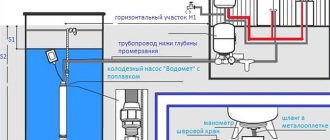
The automation operation scheme for water supply pumps and wells is not inferior in efficiency to central systems
In order for the process to be technically optimal and meet the requirements, many people prefer to buy automation for a well pump. Based on functionality, mechanisms can be divided into two types:
- automatic control of water supply;
- protective system.
Regulating mechanisms allow you to adjust the required flow. When watering - more intense, for domestic needs, including for supply to heating and household appliances - less force.
A protective mechanism prevents damage to the unit in the event of a significant voltage drop. In situations where the water level has changed, pumping is impossible; when turned on, dry running occurs.
A well-established scheme for the operation of a well and automation for water supply pumps is not inferior to central systems in terms of operating efficiency and even in some respects surpasses them. When using an individual source, interruptions and shutdowns are eliminated; electricity costs are less than paying for the amount of water consumed from the central water supply system. In cases where it is possible to use it as drinking water, the advantage becomes even more significant.
By functionality, automation is divided into regulating water supply and protective
Types of protective automation for well pumps, connecting blocks
When choosing an automation unit for a well pump, you should pay attention to the voltage indicator recommended for normal operation of the latter, and to the permissible deviations. To protect the device from running without water, it is necessary to install a U-shaped relay. This element will turn off the pump if no water flows into it.
Modern manufacturers offer several types of protective mechanisms to ensure safe operation of pumps:
- Start-protective, they are based on printed circuit boards;
- relay blocks;
- devices whose operation is provided by microprocessors.
The connection diagram of a well pump to an automatic system that prevents overheating is carried out by performing the following steps:
Modern protective mechanisms are starter-protective, relay and microprocessor-based
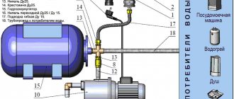
1. You need to prepare the equipment. Need to purchase:
- hydraulic tank (hydraulic accumulator);
- pressure gauge;
- adapter coupling with collet clamp;
- plastic pipes and brass adapter.
2. Wrap the entrance to the hydraulic accumulator with fum tape and screw on the adapter coupling.
3. Connect a pressure gauge and relay to the brass adapter.
4. Connect the brass adapter and the adapter coupling.
5. From a plastic pipe, assemble an elbow that will connect the relay and battery with the water supply system.
6. Connect the well pump hose using a coupling with a collet clamp.
Important! After assembling the system, be sure to ensure that the cable is securely fastened to the terminal block.
Control automation for a submersible pump
The automation system that regulates the operation of the pump consists of several elements. The main one is the control relay, which is supplemented by the electrical part. Depending on the features of the configuration, there are two principles of operation of the devices.
Regulating automation for a submersible pump consists of a control relay and an electrical part
Regulation of water pressure in the pipeline. Valid when water is supplied from a well and the system has a hydraulic tank. After the first rise, it fills the container and is then fed into the home system. Automation operating according to this scheme has a sensor with electrodes.
Some units (usually intended for wells) are equipped with special floats to control the amount of water. It should be noted that the price of submersible pumps for wells with automation of this type is quite high, but the devices are in demand. Regardless of the method of controlling the filling of the accumulator, all tanks have an emergency drain, which, if necessary, will reduce the pressure in the tank. A positive characteristic of the operation of just such a control system is the stable operation of the pump, ensured by constant hydraulics.
Level control. This is done using commands. A certain pressure is set on the relay, the pump turns on and off depending on its change. A similar scheme is actively used in private areas; it also requires the presence of a membrane tank. As positive characteristics of such a scheme, it should be noted the relative ease of installation and the low price of the automation. The ideal picture is slightly spoiled by the inaccuracy of readings and the short service life in a system with vibration pumps.
Important! When using a pressure level control circuit, the relay can be installed in the power circuit of the pump.
The pressure switch can be installed in the pump power circuit
What parts does the automatic unit consist of?
The advantage of a single unit is that all the elements necessary for the operation of the pump are collected in one device. This simplifies installation and configuration.
Control can be carried out mechanically (first generation), electromechanical and electronic methods.
Overview of automation units and pressure switches for pumps:
Second generation control units
The second generation ABU includes:
- A pressure switch that contains a membrane, a lever that transmits the force of water to a microswitch, a spring (to compensate for fluid pressure), and an adjusting screw.
- An electronic board that performs the functions of turning power on and off, voltage protection and no-load protection.
The mass of water through the membrane and the lever compresses the spring, the microswitch opens, and the electric motor stops. When the pressure decreases, the spring is released, the lever returns to its original position and starts the motor.
The required pressure of the models is established by selecting the stiffness and adjusting the compression of the spring.
Third generation
The operating principle of blocks of all generations is the same. The difference lies in the number and quality of sensors, the complexity of the electronic “stuffing”, and additional functions.
For example, in the 3rd generation two-threshold devices offered, the automation includes a two-threshold pressure sensor and a flow sensor. Accordingly, control occurs based on minimum and maximum pressure and water flow.
Signal diodes indicate the operating mode. If the red diode is on, this means that the system is in emergency mode, which can be caused by a voltage drop of less than 170 volts or a lack of water flow of 2 l/min.
Modular automation for wells, advantages and disadvantages
The modules have the following advantages:
- the service life of the electric motor increases;
- electricity is consumed more economically;
- makes setup, control and diagnostics easier;
- installation possible without a hydraulic accumulator;
- Wider protection functionality.
Existing disadvantages:
- price;
- increased requirements for power quality;
- fewer options for interchange, work with the intended brand of pump.
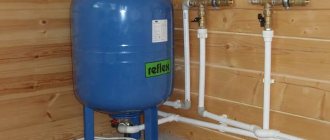
Features of connecting a hydraulic accumulator to a well
The article mentioned a hydraulic accumulator (also known as a hydraulic tank, a membrane tank) more than once. In general, the purpose of this element of the water supply system is clear, but its role is so important that the issue requires a more detailed consideration. The principle of operation of the tank is as follows:
- water enters the membrane, the free gas is compressed, increasing the pressure on the stretched rubber;
- the tank is full - the relay turns off the pump;
- after opening the tap, the pressure drops, the relay turns on the pump again and brings the pressure indicator to the required value.
The operation of the membrane tank described above directly indicates that the main type of automation for a well pump with a hydraulic accumulator is a pressure control relay. The tandem of the membrane tank and relay significantly increases the service life of the pump, since it provides protection against water hammer when starting the pump, and also reduces the frequency of switching on - a small amount of water is supplied from the tank.
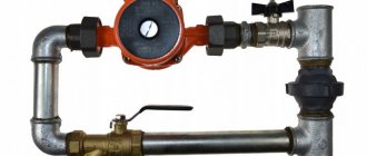
When connecting a hydraulic accumulator to a well, installing a check valve is of great importance. Its main function is to prevent water from going back into the well. The valve is mounted on the pump at its connection with the supply pipe. Mounting method: threaded. The thread is cut into the pump cover. The installation of the system has a strict sequence: first the valve is installed, then the hydraulic accumulator is connected.
Installing a check valve when connecting a hydraulic accumulator to a well plays a key role
Helpful advice! In conditions of unstable replenishment of the water layer, it is worth purchasing an automatic pump with a hydraulic accumulator with a water search function (automatic reboot) after the dry-running protection is activated.
Gearbox
Another element of the system for automatic water supply at home is a pressure regulator, or reducer.
Italian gearbox
It limits the pressure in the internal water supply to a given value.
This is necessary in two cases:
- If there are different pressure requirements in different parts of the water supply circuit;
- When connecting a house to a main water supply with pressure exceeding the standard (according to SP 30.13330.2012, 4.5 atmospheres). Deviations from standard values may be caused by the specifics of the development (neighborhood of private and multi-storey buildings) or terrain (if your house is located at the bottom of a high built-up slope).
The most common piston gearboxes operate due to the difference in the area of the piston and valve and, accordingly, the force acting on them at a constant pressure. As the pressure increases, the piston moves, overcoming the resistance of the spring, and closes the valve.
Meet the piston gearbox
Types of automation for a pump without a hydraulic accumulator
It is also possible to organize high-quality water supply from a well or well without the presence of a membrane tank in the system. The main condition is a high-quality pump, the technical characteristics of which will correspond to the operating conditions of the unit. It is also important to choose automation for the deep-well pump, which will allow you to maintain constant water pressure in the system: a pressure switch and protection against voltage surges.
The operation of water supply without a battery can be described as follows:
- when the tap is opened, sensors and relays react to pressure changes and automatically turn on the pump, which supplies water directly from the well or well;
- a closed tap helps stabilize the pressure, which is recorded by the automatic control system, and the pump turns off.
Every time you use the water supply system, even if a minimum volume of liquid is required, the pump turns on. It is this moment that most influences the wear factor - the pump fails faster than a unit that has a hydraulic accumulator in the system.
Properly selected automation can organize high-quality water supply without a hydraulic accumulator
The positive characteristics of water supply without a membrane tank include the following:
- simplicity of the pump connection diagram. The main elements are a pump and automation;
- small device sizes;
- affordable price of the system as a whole;
- the ability to supply water under high (compared to a system equipped with a membrane tank) pressure.
Protective and regulating automatic protection of the pump without a hydraulic accumulator will ensure its long-term operation without breakdowns if the system is used with a medium or low level of intensity, for example, by a family of 2 people.
Relay selection criteria
The technical characteristics of the device are indicated in the documentation. First of all, you need to know the connection dimensions - from ¼ to 1 inch - and the location (external or internal) of the thread of the connection fitting.
The nominal and maximum pressure is selected based on the operating conditions - the length of the pipeline, the number of water collection points. The pressure switch has a protection class against moisture and dust.
There are electronic devices on sale with a digital timer and push-button settings. It is believed that they are more sensitive to water pollution and require additional filters. This type of device turns off equipment more carefully, with a delay of 10 seconds.
Automation and connection of the “Malysh” well pump
“Malysh” occupies a special place among the many models of submersible pumps. Almost all summer residents and residents of country houses who use wells are familiar with it. Even if a more powerful unit was subsequently purchased, the well was pumped using the vibration “Baby”.
For long-term operation of Malysh pumps, a hydraulic accumulator is essential
Before you figure out what kind of automation is needed for the “Malysh” pump, it’s worth considering its technical characteristics:
- pump capacity – 430 l/min. (without lifting);
- rise to a height of up to 40 m;
- engine power – 250 W.
Water intake can be upper or lower, depending on the model. With the upper suction position, the engine is cooled better, since it is completely submerged in water during operation. There is also no unnecessary suction of sludge or other unwanted particles from the bottom of the well.
Important! You should not use the Malysh pump to pump out heavily contaminated water. In such a situation, rapid failure of the electric motor is inevitable.
As for the automation for the vibration pump, including the “Kid”, the most standard models are suitable. Most of the Malysh pumps have built-in protection against overheating, which can occur due to voltage surges or dry operation. Only the command relay needs to be purchased additionally. Regarding the use of a hydraulic accumulator, the situation is as follows: this unit absolutely needs it to maintain longevity. It is worth connecting a membrane tank with a capacity of 25-50 liters to the system; this is the optimal volume for the power of the “Malysh” pump.
Standard automation models are suitable for “Malysh” vibration pumps
Cost of relays and hydraulic accumulators of some manufacturers
Relay models can be purchased relatively inexpensively. Usually the cost of products does not exceed one thousand rubles. However, electronic analogues may have a higher price, as they allow for more precise adjustments. The table shows models of some manufacturers and their prices.
| Image | Model | Dimensions in millimeters | Price in rubles |
| Gilex RDM-5 | 110x110x70 | 900 | |
| Danfoss KP1 | 107x65x105 | 1 570 | |
| Belamos PS-7 | 150x80x150 | 575 | |
| Caliber RD-5 | 103x65x120 | 490 |
Related article:
As for hydraulic accumulators, their cost can be noticeably higher. It mainly depends on the volume of the structure. A large tank can significantly reduce the number of work cycles. However, there is not always enough space for it. The table shows prices for hydraulic accumulators for water supply of different sizes.
| Manufacturer | Volume in liters | Cost in rubles |
| Gilex | 24 | 1 400 |
| 50 | 3 500 | |
| 100 | 6 300 | |
| Poplar | 24 | 1 100 |
| 50 | 2 900 | |
| 100 | 5 100 |
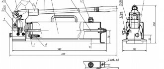
How to make a water pump with your own hands at home
Summer residents are not lazy and savvy people. Therefore, the question of how to make a water pump with your own hands without electricity is asked quite often. In fact, there are many options, all of them are quite feasible. One of the most effective and most affordable is a pump based on a pump mechanism. This is the type that is most often used in conditions where there is no electricity.
To create a pump you will need the following elements and parts:
- PVC pipe with a diameter of 5 cm;
- PPR pipe with a diameter of 2.4 cm;
- two 0.5 inch check valves;
- pipe plugs and bends;
- 8 mm bolts with nuts, rubber gaskets.
The pump is assembled from the above parts. The main thing is to ensure the tightness of the structure, otherwise the mechanism will not work. The piston creates pressure in the working chamber. Under its influence, water, passing through the valves, is supplied to the outlet. It is very important that the gaskets fit tightly.
Related article:
Pressure switch for a hydraulic accumulator: how to install and configure correctly
Purpose and installation location of the pressure switch. Rules for adjusting and configuring the device.
It is difficult to perceive when described, but in fact it does not cause problems to create a pump powered by solar energy with your own hands. The operating principle is somewhat reminiscent of how a submersible pump is connected to a hydraulic accumulator: gas takes part in pushing out water.
A pump based on a pump mechanism is the most affordable to make yourself
Required components:
- metal grate;
- rubber bulb;
- cylinder with propane-butane mixture.
The grate is filled with gas and connected to the bulb. The pear is placed in a tank pre-equipped with valves for inlet and outlet. Solar energy expands the gas, the latter pushes out air, providing a pressure difference in the water tank.
Important! All tank seams must be sealed tightly. Such a pump must be located in a well-lit place.
Reasons for decreasing pressure in the system and how to increase water pressure in the pumping station
Situations when the water pressure in a pumping station does not meet the requirements are quite common. Do not rush to adjust the operation of the automatic water pump. To solve problems, you should first carry out the following diagnostics:
Water pressure is affected not only by automation, but also by the condition of the filters, air pressure in the system, and the tightness of the suction pipeline.
- Check the condition of the filters. Impurities of sand, clay and other elements can not only clog filters, but also cause corrosion of system elements, which will certainly affect the efficiency of the pump.
- Measure the air pressure in the system. Its reduction also affects the full functioning of the station.
- Make sure the suction pipe is tight.
If, as a result of the above actions, no problems are identified, it is necessary to intervene in the operation of the automation: check the condition of the hydraulic accumulator and set the pressure switch for the well pump. Quite often a mistake is made in which a high level of lower pressure is set. The station practically does not turn off in this mode, which, naturally, has a detrimental effect on its functioning.
Low pressure can also be caused by damage to the membrane or microcracks in the tank. Sometimes it is impossible to eliminate defects; a complete replacement of the hydraulic accumulator is required.
The water pressure in the system is easily regulated automatically
Types of Pampela automation for centrifugal and vibration pumps
Among the automation systems for borehole pumps, the units produced by Pampela LLC are especially popular. The company produces two types of devices:
- Designed for vibration pumps. These include “Vistan-3”.
- Used for centrifugal pumps. Here the choice is somewhat wider: “Pampela” KIV-1B3, “Pampela” KIV-1B3, “Pampela” KIV-1A3.
The Vistan-3 device can be used when supplying water from various sources: reservoirs, reservoirs, wells, boreholes. Compatible with pumps such as “Baby”, “Rucheek”, etc.
The main functions of this type of automation include the following:
- ensuring smooth switching on and off of the pump when using a standard starting system;
- turning on the pump when the tap is opened, as they say, after receiving a certain command;
- protection from the harmful effects of voltage surges and dry running;
- can be used as a water pressure regulator in the system.
Automation for borehole pumps "Pampela" is especially popular
A deep well pump with Pampela automation will operate stably and will last much longer than a device without such protection.
Pumping automation "Pampela" KIV (1A3, 1B3, 1B3) monitors, controls and protects the operating device. Ensures switching on without water hammer, restarts the system after failures and accidents, protects against voltage surges, as well as when the pump is operating in the absence of water intake.
Helpful advice! engages in the development, production and trade of pumping automation. To avoid purchasing counterfeits and, if you want to avoid trade markups, you should buy units in the manufacturer’s stores.
Hydraulic accumulator device, principles of operation
Setting the accumulator pressure switch
To better understand the functions of individual elements, it is necessary to consider the system as a whole.
From a well or other source, water is pumped into the main pipeline. To prevent it from moving in the opposite direction, a safety valve is installed. Shut-off valves are installed in the required places. It is used for preventive maintenance, adjustments, and replacement of failed units.
Water flows through the pipeline into a special container, which performs several functions:
The main working element of such a container is a flexible partition. But the initial pressure in the tank itself is created by the pump. With appropriate equipment, it is controlled from a special remote control. Data is received there from the pressure switch for the hydraulic accumulator.
Above is part of a smart home class diagram. It connects to the general control system. In practice, more economical solutions are often used.
To successfully solve the identified problems, the following designs of hydraulic accumulators are used:
This picture shows another important element, the flow filter. It prevents the entry of mechanical contaminants, damage to the relay and blocking of its drive mechanisms. The increased tank capacity is useful not only for high daily consumption. It will reduce the number of pump starts/stops, which will have a positive impact on the durability and reliability of the system.
The standard method for calculating tank volume (VT) uses the following formula:
OB=16.5 x RV/KV x CD x 1/DVK, where:
In order not to embarrass oneself when living year-round, a tank with a capacity of 40-60 liters is sufficient for a family of three. Similar advice is given by specialized experts. In fact, it is better to make a more accurate calculation using the above method. The results obtained should be increased taking into account guest visits and other situations accompanied by increased water consumption. This approach will help you purchase a hydraulic accumulator for water supply, the price of which will correspond to the technical characteristics and needs of future users.
When placing the tank at the highest point of the structure, the force of gravity will be used. But we must take into account that the room must be reliably protected from adverse external influences. It maintains temperatures above 0°C all year round.
It is necessary to remember about the increase in mechanical loads. A large water tank weighs a lot, so sometimes additional reinforcement of the structure’s load-bearing frame is required. For these reasons, large containers are often installed in the basement.
How to install a pressure switch for a hydraulic accumulator
Before performing work operations, it is necessary to clarify the general requirements. In order for the water supply system to function optimally, the pressure difference for turning the pump on and off is set within the range from 0.9 to 1.8 atm. Exceeding it will increase energy consumption.
To calculate what pressure should be in the hydraulic accumulator (DHA), use the formula DHA = (B+6.5)/10, where:
The process of connecting a pressure switch to a hydraulic accumulator
For study, this article discusses a mechanical pressure switch for a hydraulic accumulator. This design is repeated in modifications by different manufacturers, with relatively minor changes.
This product is connected to the water supply system in assembled form. Flexible tubing designed for appropriate pressure levels can be used to place it in a convenient location. If necessary, use transition fittings. Upon completion of installation, the tightness of the threaded connections is checked experimentally.
The electrical connection can be made directly to the pump power supply circuit. Use wires designed for appropriate power. To eliminate errors, it is recommended to use products with color braiding. The “earth” standard is a combination of yellow and green. The electric motor is connected to a 220 V network through an automatic device, which ensures quick shutdown in the event of a short circuit.
All electrical installation work is carried out with the voltage turned off. It is necessary to exclude accidental supply of voltage during the process of adjusting the pressure switch for the hydraulic accumulator.
Automation for the Gilex pump: types, functions, compatibility with other devices
Automation units for Gilex 9001 pumps have also proven themselves well in the domestic market. These are universal devices that are compatible with all models of centrifugal, vibration, vortex and screw pumps. To ensure maximum efficient operation with pumping devices, it is necessary that the latter have the following technical characteristics:
The Gilex automatic system has also proven itself to be excellent.
- had a throughput capacity of up to 100 l/min;
- operated on a network voltage of no higher than 230 W;
- the current was 6-8 A;
- the pumped water did not exceed a temperature of 75 °C;
- the pipe had a cross-section of 1 inch.
It is very important to install the automation unit correctly. It should be noted that Gilex devices are powered from a regular household electrical outlet. The devices are installed only vertically, the blue cover must be in the upper position. Automation is installed between the point of consumption and the pump.
Automation for the Gilex well can be of different modifications. In particular, the kit sometimes lacks measuring instruments. In such cases, a pressure gauge should be purchased additionally and installed on the side panel.
Gilex also produces other, simpler types of automation. These include the “Crab” systems. They maintain the required pressure in the line and turn the pump on and off if necessary. Their design includes a filter that purifies the water from solid impurities.
Automation "Dzhileks" is installed only vertically
The RDM-5 relay version maintains the required pressure level in the water supply system. The device is simple, compact, inexpensive. Connects to the pump using an electrical cord. If the pressure drops, contact appears, the pump begins to pump water into the system. At normal (user-set) pressure there is no contact and no water is drawn.
What is well automation?
The automation unit for submersible or surface pumps is a modern electronics unit that includes a hydraulic accumulator, modules and a pressure gauge. All of them guarantee the correct operation of the highway.
Automation functions for water pumps:
- Control. All processes are carried out automatically, without control or supervision.
- Protection against water hammer. A water reserve is created in the main line in case of equipment malfunction or breakdown.
- Electronic devices are triggered in the absence of a liquid medium and turn off the electric current.
Automation for a water supply pump without a hydraulic accumulator helps prevent equipment breakdown and premature failure.
Automation device for a well.
Rules for installing and configuring AQUAROBOTA TURBIPRESS
The AQUAROBOT TURBIPRESS block is designed for automatic control of both surface and submersible pumps. This automation is compatible with single-phase pumping devices whose power does not exceed 1.5-2.2 kW.
The main functionality of the automation is as follows:
- pump control by maintaining user-specified upper and lower pressure in the system;
- turning off the pump if there is no possibility of water intake;
- maintaining the operating condition of the system when the voltage drops to 170 V.
"AQUAROBOT" has the following technical characteristics:
The connection diagram for a deep-well pump with automatic “TURBIPRESS” is standard
- permissible operating voltage – 170-250 V;
- maximum current – 16-20 A;
- maximum pump capacity – 120 l/min., minimum – 3 l/min.;
- pressure level for switching on – 0.5-4.5 bar, for switching off – 2-5 bar;
- protection response rate is 5.5-7 bar.
The connection diagram for a deep-well pump with automatic “TURBIPRESS” is standard: the unit is installed on the pressure pipe of the pump up to the first point of water consumption from the system.
It is not allowed to connect this automation to a system without a hydraulic accumulator. The minimum volume of the membrane tank must be at least 20 liters.
Important! When using a vertical hydraulic accumulator in the system, you cannot install the TURBIPRESS automation on the flange of the membrane tank.
“TURBIPRESS” automation cannot be connected to a system without a hydraulic accumulator
Adjustment
How is the automated water supply of a private home configured, and in what cases is it necessary to configure the equipment?
Let's start with the second question.
Adjustment allows:
- Increase the pump shut-off pressure and, thereby, the maximum pressure in the water supply;
- Raise the cut-in pressure by reducing the pressure delta. Constant changes in pressure over a wide range are inconvenient if, for example, you wash dishes under a thin stream of water;
- Reduce the shut-off pressure and, subsequently, the frequency of pump activation. It is the number of starts that determines the service life of the device: starting currents and significant mechanical loads at the moment of switching on significantly reduce the service life of any equipment;
- Change the pumping pressure of the hydraulic accumulator (pressure in the air compartment when the water supply is empty), thereby reducing or increasing its capacity;
Useful capacity of a membrane accumulator depending on the pumping pressure and automation settings
- Adjust the constant pressure in the water supply or in a separate section of it (say, in front of the washing machine and dishwasher) using a reducer.
Let's move on to the setup methods.
Relay
If electronic relays are configured through the control panel, then in the case of an electromechanical device we will need to open its housing.
Captain Obviousness suggests: for safety reasons, the relay or pumping station must first be disconnected from the power supply.
Under the cover you will see two springs with nuts of different sizes.
The photo shows a pressure switch with the cover removed
The large one is responsible for the shutdown pressure (clockwise rotation increases it, counterclockwise decreases it). The small nut, when tightened, increases the pressure delta between the cut-off and cut-off points.
Relay settings
Hint: as a rule, the factory settings of the relay are 3/1.5 kgf/cm2. They are safe for any pipes (including polymer ones) and ensure the normal operation of household and sanitary equipment.
Hydraulic accumulator
To adjust the pumping pressure, we need to find a nipple on the body of the membrane tank. Usually it is hidden under a metal or plastic cap. The design and size of the nipple are no different from a car or bicycle valve.
Nipple in the air compartment of the hydraulic accumulator of the pumping station
To bleed air from the membrane tank, just press with a screwdriver or any other suitable-sized object on the short rod in the center of the nipple. You can pump it up with a pump or compressor (preferably with a built-in pressure gauge).
Inflating a membrane tank with a car compressor
Attention: the tank pumping pressure must be lower than the pump shutdown pressure. Typically these values differ by 0.2-0.3 kgf/cm2. Otherwise, you will experience a short-term interruption in water supply when the water compartment of the accumulator is empty.
Gearbox
The adjusting screw is usually hidden under a plastic cover at one of the ends of the pressure reducer. Adjustment is made with a wide flat screwdriver: turning clockwise increases the water pressure in the internal water supply.
Screw for gear adjustment
Well pump with automation: operating features, connection
Is there a difference between borehole and sump pumps? Yes, but it would be more accurate to say that pumps with certain technical characteristics are used to pump water out of a well. These are monoblock centrifugal devices, where the engine, water intake elements and pipe are located in one housing.
The well pump is installed at a depth of no more than 25 m. It has a rather low performance. The pump for an automatic well should be positioned so that it does not drift along the water layer. It is also necessary to eliminate vibrations of the unit, as they will raise all sorts of unwanted particles from the bottom.
It should be noted that the protection against solid particles entering and sticking to the wheel blades in well pumps is weak. Therefore, when pumping contaminated water, they quickly lose their rated performance.
Well pumps, that is, centrifugal ones, differ from vibration pumps in the way they are protected from running dry. It consists of the following: when the intensity of the water flow entering the pump decreases (when air enters), the current strength of the device’s electric motor also decreases. The sensor reacts to the current situation by giving a signal to turn off the unit.
Connecting a submersible pump for a well is carried out according to the same scheme as for a well
The connection diagram for a submersible pump for a well is almost the same as for a well pump. The only difference is in the method of fixation: the borehole is attached to the head; for a well, a metal frame is made, a hole is made in it, into which the cable is inserted.
Purpose of the pump control cabinet
Connecting the pump to the automation is not complete without installing an electrical cabinet. It is especially important in a water supply system powered by a submersible unit. All control, monitoring and fuses are located inside the cabinet.
The automatic machines installed in the cabinet perform a smooth start of the engine. Easy access to the equipment allows you to adjust the frequency converter, measure current characteristics at the terminals, and adjust the rotation speed of the pump shaft. If several wells with pumps are used, all control devices can be placed in one cabinet. The photo shows a typical diagram of equipment that may be located in a cabinet.
The video talks about pump control:
How to raise water to a height without a pump: video, description
Do not rush to assess the conditions for cultivating soil without electricity as extreme. It is in such situations that a considerable number of gardeners find themselves who have developed plots of land in vacant lots and other unclaimed areas. Ingenuity and useful experience, which many share on the Internet, make it possible to organize water supply without electricity.
There are quite a few such pumping methods. The most accessible ones include the following:
An Archimedes screw is a device consisting of a cylinder and a screw placed in it with a handle for rotation.
- Application of the Archimedes screw. The device consists of a hollow cylinder and a screw placed inside it with a handle for rotation. The system must be lowered into the source at an angle. A mechanically driven screw takes in water and delivers it upward.
- Using a hydraulic ram. The method was invented by the Montgolfier mechanic. It is based on the kinetic energy of water: the flow passing through a rigid pipe is blocked, and water flows through a check valve into the hydraulic tank located above. The tank is equipped with a fitting at the bottom, onto which a hose is placed that supplies water to the consumer.
To get more information on how to raise water to a height without a pump, it is worth watching the video:
Helpful advice! When creating a mechanical water supply device, it should be taken into account that the most effective and affordable method is a piston system.
Installation of a surface electric pump
Installation of a surface electric pump.
Pumping equipment with automation is installed in a room or caisson. The latter option is more expensive, but in some cases it is preferable. It is difficult or impossible for surface devices to lift water from a depth of more than 8 m.
The caisson will allow the unit to be lowered 1 m below the surface, increasing the pressure. Everything necessary is installed at the station; only the pipes are connected.
The diameter of the input element is 25 or 35 mm. A check valve is installed at the other end through the fitting. Lower the pipe into the well so that it is immersed 1 m in the liquid. The station and inlet pipe are filled with water through the filler hole. Turn on the unit - if the connections are sealed, water will be pumped.