Dear site visitors!!!
I believe that the information presented in this topic will be useful to you. The topic will address various issues in this area, and many questions arise in this area:
- How does a household fan electric motor work?
- how to replace a capacitor in a fan's electrical circuit;
how to rewind the fan motor stator, how to repair:
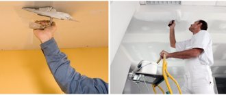
- wall fan;
- ceiling fan;
- window fan;
- floor fan;
- bathroom fan;
- kitchen fan;
- fan with timer;
- exhaust fan.
It is almost impossible to immediately and completely provide information on issues that arise related to malfunctions resulting from the operation of various types of electric fans.
The topic will gradually expand, that is, after a certain period of time, additions will be made.
Take an interest in various sources of information in this direction:
- technical sites;
- technical literature
and so on. Accumulate your experience and knowledge.
How to connect a single-phase electric motor - circuit with a capacitor
The operation of a single-phase electric motor is based on the use of alternating electric current by connecting to single-phase networks. The voltage in such a network must correspond to the standard value of 220 Volts, frequency - 50 Hertz. Motors of this type are primarily used in household appliances, pumps, small fans, etc.
The power of single-phase motors is sufficient for the electrification of private houses, garages or summer cottages. Under these conditions, a single-phase electrical network with a voltage of 220 V is used, which places some demands on the process of connecting the motor. A special circuit is used here, which involves the use of a device with a starting winding.
Switches and thermostat
What other electrical elements in the circuit can fail? Immediately after the power wires there is a thermostat and a mode switch.
On the outside of the case there are the familiar “handles and wheels” that are familiar to everyone.
Some people mistake the thermostat for an element that regulates the speed of rotation of the blades. In fact, this is a bimetallic strip, and one of the power wires from the plug comes directly to it.
When you twist this knob, a barely audible clicking sound should be heard. This means the thermostat turns on and off. If the circuit does not have a separate microswitch, then it also performs its function.
But his main task lies elsewhere. When the heater and heater body reach a certain temperature (which you set by twisting the knob), the bimetallic plate inside the thermostat bends and snaps off its contacts - the fan is completely turned off.
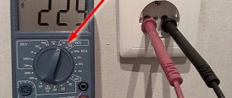
The serviceability of this element is also checked with a multimeter. Place two probes on the contacts and turn the knob. In call mode, the sound will appear and disappear.
The mode switch is checked using the same scheme. By turning its handle, you turn on one heater, two, or simply put the fan in fan mode without heating.
Only when you remove the terminals for testing, it is better to take a photo of their initial connection on your smartphone in advance, so as not to confuse the contacts later.
The currents in these elements are not weak - about 10A. Therefore, the loss of a chain in them is not so uncommon. True, the very first check of the thermostat and the 4-position switch can be done “by smell”.
Burnout of contacts under such a load never goes away without leaving a trace. Such things will definitely smoke and stink.
Description of the machine
Single-phase electric motors are usually called asynchronous single-phase electrical machines with low power. The magnetic core of such machines has a two-phase winding, which is divided into a starting (starting) and a main winding. The need for 2 windings is as follows: they must cause the rotor of the electric propulsion (single-phase) to rotate. At the moment, such devices are conventionally divided into 2 categories:
- Presence of starting windings. In this embodiment, the starting winding is connected through a starting capacitor. When the start is complete and the machine has reached its rated rotation speed, the starting winding is disconnected from the power supply. After which the engine continues to rotate on the working winding connected to the network (the capacitor charges during startup and turns off the starting winding). The required capacitor volume is usually indicated by the machine manufacturer on a plate with all the parameters (as a standard it should be on all engines).
- Machines with working capacitors. In such electrical machines, the auxiliary windings are always connected through capacitors. In this case, the volume of capacitors is determined by the design of the engine. In this case, the capacitor remains switched on even when the machine reaches the nominal operating mode.
To correctly connect an electrical machine, you must be able to determine (or know) how the starting and operating windings are wired, as well as their characteristics.
It is worth noting: these windings differ in the conductors used (their cross-section), as well as in the turns. So, for the working windings, conductors of a larger cross-section are used, and they have a larger number of turns. It is important to know that the resistance of the working windings of different machines is always less than the resistance of the starting/auxiliary windings. In this case, measuring the resistance of the motor winding is not difficult, especially if special multimeters are used.
Based on what has been described, it is worth giving some examples.
Doesn't respond when turned on
If the fan heater does not turn on when connected to the network and pressing the button, there may be several reasons for the malfunction. The first thing to do is check the electrical cord; perhaps it was broken somewhere during summer storage. Did not help? We take a screwdriver and a multimeter, after which we proceed to repair the fan heater ourselves. Most likely the cause of the malfunction is the fuse box, one of which tripped due to overheating.
Using the example of the Scarlett SC158
Let's look at step-by-step instructions on how to fix a fan heater with your own hands:
- First, we unscrew the screws on the back cover, there are usually 6 of them, as shown in the photo.
- Next, we use a multimeter to test the main elements of the circuit: thermal fuses, thermostat, thermal switch. The first fuse can be seen immediately without removing the blade. To find the second one, which is located on the engine, you will have to remove the fan. You test the circuit yourself with a multimeter and if this type of breakdown is really the cause, buy exactly the same element in the store and replace it (cost no more than 30 rubles).
- If the thermal fuses are working, check the Polaris heater control unit. It can be found according to the diagram provided in the instructions for the device.
Please note that replacing fuses with thin wires (bugs) is strictly prohibited. With this method of repairing a fan heater with your own hands, you will make a fire-hazardous heater that will not operate if it overheats! Video repair instructions:
Video repair instructions:
How to find a breakdown with a multimeter and repair it
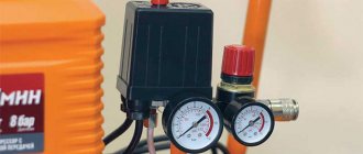
Calculation of motor capacitor capacity
The winding with a smaller cross-section is the starting one. Such devices have a power factor greater than that of the short-circuited devices described above and develop greater torque in comparison with them. You can do this yourself or use online calculators. The circuit with a working capacitor does not provide for disconnecting the additional winding after starting and accelerating the engine. From a single-phase network, three-phase devices operate using capacitive or inductive-capacitive phase-shifting circuits.
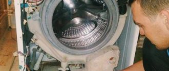
Capacitors Our readers recommend! How to connect the electric motor of a washing machine Modern washing machines can have either commutator or three-phase motors. Each of the listed connection diagrams is suitable for use in the operation of asynchronous single-phase electric motors.
In this case, the functions of the switch can be performed by a specially designed relay.
An axial groove divides each of them into two asymmetrical halves, the smaller of which contains a short-circuited turn.
If to connect an asynchronous motor you use not a three-phase network, but a household single-phase one, that is, power it through one winding, it will not work. Connecting capacitors (part 1)
Installation Features
Before starting installation, it is necessary to register and approve this project with the government agencies responsible for the operation of the building . It should list the conditions for using the entire future ventilation system, the procedure for performing the work, the materials used and the layout of the ventilation air ducts and shafts.
Duct fans can be installed anywhere in the air duct and at any angle; the most cost-effective option is the rectangular cross-section of all air ducts, which saves free space.
To increase productivity, several fans are installed in parallel, and to increase the operating pressure they are mounted in series.
For ventilation of any size bathroom, one duct product is sufficient. To ensure tightness, special components are used, and to eliminate unwanted vibration, gaskets made of a material that absorbs the negative effects of vibrations and reduces noise from the operation of the device are used.
Subscribe to the newsletter
An exhaust fan is a device that can increasingly be seen in the homes of our fellow citizens. There are several reasons for this. Firstly, recently, thanks to a significant reduction in the cost of production of such devices, almost everyone can afford such a purchase. Secondly, this electrical appliance is certainly a very useful acquisition for an apartment or a private house.
Electrical circuit of a household fan and its features
The main task of an exhaust fan is to provide forced artificial air circulation in rooms where natural circulation is difficult or insufficient. A striking example of such a room is the bathroom. In apartment buildings, as a rule, this room is located far from the external load-bearing walls, and, therefore, air circulation in them is difficult. If we add to this increased humidity and the mold that arises from it, then it immediately becomes clear that an exhaust fan in the bathroom is not just a tribute to fashion, but a real necessity.
In order to connect the fan, you need to know a few small nuances. You need to understand that the electrical connection diagram of the fan is largely determined by the location of its installation and the presence of design features.
Basic connection diagrams:
1. Connection with built-in switch. The simplest scheme. The device is supplied with 220 V power. The fan is turned on and off using a switch built into the device.
2. Connection via a switch. Using this scheme, the fan is turned on and off using a special switch. As a rule, it is located in front of the entrance to the room. For such a connection, it is necessary to lay 2 cables - one from the junction box to the switch, the second to the device itself.
3. Connecting a fan with a timer. The peculiarity of these devices is that they do not turn off immediately, but after a certain time. This is done through a special time relay, which automatically turns off the device after a predetermined period of time (usually from one minute to half an hour). With this connection, one wire goes to the switch, and two to the device.
4. Connecting a fan with a humidity sensor. The electrical fan control circuit may include a humidity sensor that measures readings in real time and, in accordance with a given program, monitors the operation of the device - it turns it on when humidity rises and turns it off when it reaches optimal values. The device connection diagram is similar to that needed to connect a fan with a timer.
Most fans consist of switching circuits, starting circuits, and electric motor windings. The items on the list concern repairs. Often in household models, a trivial coil is used, wound with a copper core with varnish insulation. Today we will consider how to repair fans with your own hands, the inductance burned out, the wire broke due to the carelessness of the operator. To restore the coil, a good old device is used, despite its simplicity, you cannot get it in the store. With the help of a mechanism, inductors are wound using an electric drive, working with handles.
Industrial fans are different; unlike household fans, they are often centrifugal. The winding of a commutator asynchronous motor cannot be restored at home; it will be difficult to do. Craftsmen repeat the factory production cycle in their native lands.
Design of a typical floor fan
Do-it-yourself floor fan repair is on the agenda! You should start small: the simplest fans do not have a ground terminal. The device does not have a degree of electrical safety. The floor fan device includes a housing made of plastic. Water will get inside - expect a good shake. This type of floor fan should not be used near water. Starting with an aquarium with fish, ending with a flower vase. Particularly dangerous where small children live. If the thing falls, the child will guess to pour milk inside... Draw your own conclusions:
- the structure is unstable;
- the base breaks easily and bends;
- There is no protection against electric shock.
If a floor fan falls, there is a high probability that nothing will happen. Let's dive inside the structure. Let's leave aside for now the features of regulating the engine speed and buttons. Let's talk about the gearbox. The Krasnodar floor fan carries one asynchronous capacitor motor. The front side of the shaft is connected to the blades through a pin and a nut with a left-hand thread, the rear side goes to a gearbox formed by two gears, one double.
The shaft is equipped with a thread that engages the teeth of a large wheel as it rotates. The moment is transmitted to the small wheel, which drives the flywheel. The gear of the crank mechanism is the diameter of a hand, so the rotation is inferior to the speed of the original shaft of the asynchronous motor.
- The blades spin at full motor speed.
- The crank mechanism, thanks to the gearbox, moves more slowly.
Through the cardan transmission, the crank is hooked onto the leg, and the engine housing is mounted on the axle. When the shaft of an asynchronous motor rotates, the blades move smoothly in one direction or the other. However, you can stop the process. For a double gear, the roller is attached to the larger gear by two balls with a spring inserted into a through hole. If you pull the adjuster knob directly connected to the axle, the latch slides up. The connection between the gear and shaft is lost, and rotation stops. The mechanism provides fall protection: six grooves are cut into the inner mounting hole of the drive gear. Balls fit. There are six positions, the mutual transition is accompanied by a click, the axis rotates relative to the gear, the balls hit the walls, sliding into the grooves.
Clicking sounds are heard, there is a high probability that the floor fan has fallen. The drive is jammed, it works, clicking, a protective mechanism, protecting the motor from combustion.
We believe that the mode is unfavorable for a floor fan; if you do not turn off the device, the thermal fuse of the motor will certainly break. The gearbox is attached to the engine with three bolts and has a pair of lubrication holes through which the plastic gears can be lubricated. Refers to a drive rotating at the speed of an asynchronous motor.
Headache, how to fix a floor fan and assemble it. We see the situation: the relative position of the gearbox is incorrectly set, the legs through the gear, the head of the floor fan will move asymmetrically relative to the frontal plane. Can be annoying. Attach the gearbox, check the product by connecting power. Be careful not to get an electric shock, try to visually determine the correctness of the assembly.
Connection diagram for a single-phase motor via a capacitor
Single-phase 220V electric motors are connected to the network using a capacitor. This is due to some design features of the unit. Thus, on the motor stator, an alternating current winding creates a magnetic field, the pulses of which are compensated only if the polarity changes with a frequency of 50 Hz. Despite the characteristic sounds that a single-phase motor makes, the rotor does not rotate. Torque is created through the use of additional starting windings.
To understand how to connect a single-phase electric motor through a capacitor, it is enough to consider 3 working circuits using a capacitor:
- launcher;
- working;
- operating and starting (combined).
Each of the listed connection diagrams is suitable for use when operating 220V asynchronous single-phase electric motors. However, each option has its own strengths and weaknesses, so they deserve a more detailed look.
The idea of using a starting capacitor is to include it in the circuit only at the moment the motor starts. For this purpose, the circuit provides for the presence of a special button designed to open the contacts after the rotor reaches a given speed level. Its further rotation occurs under the influence of inertial force.
Maintaining rotational movements over a long period of time is ensured by the magnetic field of the main winding of a single-phase motor with a capacitor. In this case, the functions of the switch can be performed by a specially designed relay.
The connection diagram for a single-phase electric motor through a capacitor assumes the presence of a spring push button that breaks the contacts at the moment of opening. This approach makes it possible to reduce the number of wires used (the use of a thinner starting winding is allowed). To avoid short circuits between turns, it is recommended to use a thermal relay.
When critically high temperatures are reached, this element deactivates the additional winding. A similar function can be performed by a centrifugal switch installed to open contacts in cases where the permissible rotation speed is exceeded.
To automatically control the rotation speed and protect the motor from overloads, appropriate circuits are developed, and various corrective components are introduced into the design of the units. The centrifugal switch can be installed directly on the rotor shaft or on elements associated with it (direct or gear connection).
The centrifugal force acting on the load contributes to the tension of the spring connected to the contact plate. If the rotation speed reaches the set value, the contacts close and the current supply to the motor is stopped. It is possible to transmit the signal to another control mechanism.
There are variants of schemes in which a centrifugal switch and a thermal relay are provided in one structural element. This solution makes it possible to deactivate the engine through the thermal component (if critical temperatures are reached) or under the influence of the sliding element of the centrifugal switch.
If the motor is connected through a capacitor, distortion of the magnetic field lines in the additional winding often occurs. This entails an increase in power losses and a general decrease in the productivity of the unit. However, good starting performance is maintained.
The use of a working capacitor in a circuit connecting a single-phase motor with a starting winding involves a number of distinctive features. So, after starting, the capacitor does not turn off; the rotor rotates due to pulse action from the secondary winding. This significantly increases the engine power, and proper selection of capacitor capacity allows you to optimize the shape of the electromagnetic field. However, starting the engine takes longer.
The selection of a capacitor of suitable power is made taking into account current loads, which allows optimizing the electromagnetic field. If the nominal values change, fluctuations in all other parameters will occur. The shape of magnetic field lines can be stabilized by using several capacitors with different capacitive characteristics. This approach allows you to optimize the performance of the system, but it does introduce some difficulties during installation and operation.
The combined circuit for connecting a single-phase motor with a starting winding is designed to use two capacitors - a working one and a starting one. This is the optimal solution for achieving average performance.
Breakdowns that you can fix yourself at home
Fan blade deformation
Happens quite often since the propeller itself is made of plastic. The blades may become deformed when exposed to high temperatures. As a result of deformation, the blades touch the protective mesh, and a characteristic unpleasant noise occurs. Usually the deformation is corrected manually, otherwise the blades and protection will very quickly become completely unusable.
Deformation of the protective fence
It usually appears as a result of a falling floor fan. The fence itself is made of relatively thin metal wire and includes two parts - front and back. The front part is very easy to remove, but the back part will require some fiddling. The propeller is removed from the electric motor shaft, after which the large plastic nut is unscrewed and then the guard itself is removed. After straightening, the protection is assembled in the reverse order.
Turns to the sides stop
The main reason for this could be a disconnected crank. It is necessary to disassemble the device body and tighten the fastening screws if they are loose or unscrewed. In addition, interruptions may occur in the turning mode. To determine the cause, the gear engagement of the gearbox is checked, as well as the operation of the switch. If necessary, the gearbox is lubricated with a special lubricant. In case of severe wear, it is recommended to replace the parts. If there are no replacement parts, the fan can be used in normal mode, without turning on the turns.
Switch fault
May cause interruptions in operation. To check its condition, you need to remove the switch and determine the condition of the contacts. If necessary, the contacts are cleaned with sandpaper.
The fan doesn't work at all
In this case, you should check the serviceability of the electric motor. If it turns out that the electric motor is faulty, then repairing floor fans, in this case, is not economically feasible.
Despite their simple design and the absence of any external negative factors, household fans break down. Even an exhaust fan can fail within a year. And this despite the fact that, in addition to the impeller with an electric motor, there is only one more switch. It would seem that there is nothing to break. But it all depends on the load on the exhaust fan.
Probably modern manufacturers of this electrical equipment, understanding its potential durability, decided to help themselves: by increasing the number of fans sold, purchased to replace broken ones. And in order for a breakdown to occur and occur in the future not so distant from the date of purchase, a small part is installed in the electric motor - a temperature fuse. And within about a year, with sufficiently long operation, this part burns out and the electric motor stops rotating.
After this, as planned by the manufacturer, the owner of the fan will go to the store to buy a new one. But instead, you can repair the electric motor yourself and save money. To do this, you will need to disassemble the case and remove the engine from it. Disassembly must be done carefully, taking into account the design features. And they are such that some parts can be glued. And in order not to break them, you will need to separate them along the glued seam with a knife blade.
The fuse is located in the engine. This is a very small part to which two wires are attached.
The purpose of the fuse is to break the circuit when the electric motor overheats and turn it off. But why “overheating” and breaking the electrical circuit occurs at temperatures that are not dangerous for the materials from which the engine is made is not clear. The body of the part indicates a temperature of 125 degrees Celsius. Fan engines from the times of the USSR did not contain such a part, and some of them still regularly spin the impellers. Therefore, it is possible to exclude this fuse from the electrical circuit, so to speak, “based on the experience of previous generations.”
Removing the faulty part:
To simplify repairs, we solder a jumper made of thin copper wire on the existing contacts. Then we insulate the resulting shunt with insulating tape.
We check the result of the work. Observing safety precautions, with the voltage turned off, connect the motor to the outlet. After this, we apply voltage and make sure that the shaft rotates. Lubricate the shaft bearings. We assemble the fan and continue to use it. Don’t forget to clean it from dust, dirt, and lubricate the bearings once a year.
Functionality check
How to check engine performance by visual inspection?
The following are defects that indicate possible problems with the engine; they could be caused by improper operation or overload:
- Broken support or mounting gaps.
- in the middle of the engine has darkened (indicates overheating).
- through cracks in the housing.
To check the performance of the engine, you should first turn it on for 1 minute, and then let it run for about 15 minutes.
If after this the engine is hot, then:
- Perhaps the bearings are dirty, jammed, or simply worn out.
- The reason may be that the capacitor capacitance is too high.
Disconnect the capacitor and start the motor manually: if it stops heating, you need to reduce the capacitor capacitance.
Basic faults and repairs
The listed list of microwave oven malfunctions is not exhaustive; it only reflects the most common breakdowns. You can fix all of the listed faults yourself.
| Problem | Possible reasons | Solution |
| Microwave won't turn on | Power fuse blown, replace only | After replacing the fuse, check the serviceability of the transformer and the transformer safety diode |
| The clock is running | Miniature door switch does not operate | Repair or replacement |
| The microwave oven periodically turns off and on every few minutes | Cooling fan malfunction, fan switch relay, vents closed | Minor repair or replacement |
| During operation, sparks are visible and a burning smell is heard. | Breakdown of the mica gasket due to contamination | Replacement |
| Microwave doesn't heat well | low voltage in the network or loss of magnetron emission. Application of a voltage stabilizer | DIY repair by increasing the number of turns or replacing the magnetron |
| The LCD display does not display all segments, highlights and spots | The screen or processor is damaged. If the microwave also doesn’t work, then it’s definitely the processor. | Replacement |
| Touchpad stopped working | Damaged conductive paths | DIY repair by laying wires or replacement |
| The tray rotates jerkily | Roller grooves dirty, motor malfunction | Do-it-yourself repair by cleaning the roller grooves, replacing the engine |
| The light is on, the tray is spinning, the microwave is not heating | Severe voltage drop in the network, a breakdown in the transformer power circuit, a broken magnetron | Installation of a voltage stabilizer, repair by ringing the transformer power circuit with a tester, troubleshooting, replacement of the microwave generator |
| Buttons on the control panel do not turn on | Do-it-yourself repair by checking with a tester, soldering contacts or replacing buttons | |
| There is a humming sound when the microwave oven is operating | The fan, doubler diode or transformer has failed | Replacement |
| Microwave works without turning off | The voltage supply relay is faulty (contacts sticking) | Power off, replace. There may also be a problem with the processor or relay control circuit. Self-repair by checking with an ohmmeter, if the circuits are ok, replace the processor module |
You can repair a microwave oven with your own hands, but you can operate it correctly and thereby significantly increase its impeccable service life.
Every second kitchen uses a microwave to quickly heat up food; it is easy to use and saves quite a lot of time. Repairing microwave ovens Samsung, Panasonic, LG and others can easily be done with your own hands at home, without contacting service centers.
Despite the apparent complexity of the operation, any microwave consists of fairly simple parts: a food heating chamber, a magnetron, a waveguide and a winding, which is necessary to power the device. The camera and magnetron are connected to each other using a waveguide. In addition, a transformer and its winding are also installed in the furnace. The operating principle is as follows: when the microwave oven is turned on, voltage is supplied to the primary winding of the transformer. At the same time, energy is also supplied to the secondary winding, which is responsible for heating the cathode. Both windings are very well insulated.
Photo - microwave oven design
It should be noted that this device uses doubling the voltage, which is why the food heats up at such a speed. For this function, a capacitor is used, to which a rectifying diode is connected in parallel. To control the time, a timer is used on the gears, which helps control the duration of heating. A special temperature sensor also has a similar function.
Photo - diagram
Considering that this device is an increased source of danger, it has a built-in system that is responsible for the safety of use. These include phase and power protection relays that stop the microwave oven when there is a power surge or the door is open.
Photo is a simple device
The most common problems faced by microwave oven owners are:
Video: repair and diagnostics of microwave ovens
Asynchronous or collector: how to distinguish
In general, you can distinguish the type of engine by a plate - a nameplate - on which its data and type are written. But this is only if it has not been repaired. After all, anything can be under the casing. So if you are not sure, it is better to determine the type yourself.
This is what a new single-phase capacitor motor looks like
How do collector motors work?
You can distinguish between asynchronous and commutator motors by their structure. The collectors must have brushes. They are located near the collector. Another mandatory attribute of this type of engine is the presence of a copper drum, divided into sections.
Such motors are produced only as single-phase ones; they are often installed in household appliances, as they allow one to obtain a large number of revolutions at the start and after acceleration. They are also convenient because they easily allow you to change the direction of rotation - you just need to change the polarity. It is also easy to organize a change in the rotation speed by changing the amplitude of the supply voltage or its cutoff angle. That is why such engines are used in most household and construction equipment.
Commutator motor structure
The disadvantages of commutator motors are high operating noise at high speeds. Remember a drill, an angle grinder, a vacuum cleaner, a washing machine, etc. The noise during their operation is decent. At low speeds, commutator motors are not so noisy (washing machine), but not all tools operate in this mode.
The second unpleasant point is that the presence of brushes and constant friction leads to the need for regular maintenance. If the current collector is not cleaned, contamination with graphite (from brushes being worn out) can cause adjacent sections in the drum to become connected and the motor simply stops working.
Asynchronous
An asynchronous motor has a stator and a rotor, and can be single or three-phase. In this article we consider connecting single-phase motors, so we will only talk about them.
Asynchronous motors are characterized by a low noise level during operation, therefore they are installed in equipment whose operating noise is critical. These are air conditioners, split systems, refrigerators.
Structure of an asynchronous motor
There are two types of single-phase asynchronous motors - bifilar (with a starting winding) and capacitor. The whole difference is that in bifilar single-phase motors the starting winding works only until the motor accelerates. Afterwards it is turned off by a special device - a centrifugal switch or a start-up relay (in refrigerators). This is necessary, since after overclocking it only reduces efficiency.
In capacitor single-phase motors, the capacitor winding runs all the time. Two windings - main and auxiliary - are shifted relative to each other by 90°. Thanks to this, you can change the direction of rotation. The capacitor on such engines is usually attached to the housing and is easy to identify by this feature.
You can more accurately determine the bifilar or capacitor motor in front of you by measuring the winding resistance. If the resistance of the auxiliary winding is twice as large (the difference can be even greater), most likely this is a bifilar motor and this auxiliary winding is a starting winding, which means that a switch or starting relay must be present in the circuit. In capacitor motors, both windings are constantly in operation and connecting a single-phase motor is possible through a regular button, toggle switch, or automatic machine.
Fan composition
A typical fan includes:
- AC, DC motor;
- flywheel;
- buttons, relays, contactors;
- automatic regulation circuit.
Optionally there are no elements, the repair diagram looks like this:
- First of all, let's ring the motor windings. Regardless of the design, there are coils inside that give (on the tester screen) a resistance of a few to tens of ohms. Please note: the starting windings of asynchronous motors ring after the capacitor. The obvious point is that ignoring the rule leads to confusion. The capacitor rotates the voltage phase by 90 degrees, helping to create the correct field distribution inside the stator. If the motor is a commutator motor, the windings are connected in series (there is no capacitor). It is wise to ring the motor at the input, since the fault may be hidden in another place. Whether the break is detected or not, remove the brushes and take care of the commutator second. We call the sections one by one. If a malfunction is detected, the maintainability of the cooling fan is assessed by design. It's difficult to do, try to find a new manifold. Needless to say, the drum does not break in asynchronous motors with a squirrel-cage rotor. The current of the “squirrel cage” is relatively small; the copper rolled inside, on the contrary, is thick.
- Secondly, the serviceability of cores, relays, and buttons is assessed. The circuit rings, including the conditions for the thermostat to operate. The implementation method is determined by the design. Simulate heating by using a lighter to heat the sensor. The approach is reasonable in kitchen hoods and other appliances where the temperature is relatively high. The buttons are checked for the passage/interruption of electric current in their respective positions. Do-it-yourself repair of household fans often concerns switching. The buttons are pressed inaccurately and liquid spills. It is necessary to restore the correct functioning of the mechanical part and clean the contacts. Anyone who spilled jam on the TV remote control will understand the situation. The mechanism is disassembled, the contacts are cleaned. It would be useful to recall that the capacitor passes alternating current; in the best case, two operations are performed: they call the element to check for a short circuit (this is a breakdown), apply alternating current power and check the passage of the signal from the winding. We can say with complete confidence whether the capacitor is broken.
Connection diagrams for single-phase asynchronous motors
With starting winding
To connect a motor with a starting winding, you will need a button in which one of the contacts opens after switching on. These opening contacts will need to be connected to the starting winding. In stores there is such a button - this is PNDS. Its middle contact closes for the holding time, and the two outer ones remain in a closed state.
Appearance of the PNVS button and the state of the contacts after the “start” button is released"
First, using measurements, we determine which winding is working and which is starting. Typically the output from the motor has three or four wires.
Consider the option with three wires. In this case, the two windings are already combined, that is, one of the wires is common. We take a tester and measure the resistance between all three pairs. The working one has the lowest resistance, the average value is the starting winding, and the highest is the common output (the resistance of two windings connected in series is measured).
If there are four pins, they ring in pairs. Find two pairs. The one with less resistance is the working one, the one with more resistance is the starting one. After this, we connect one wire from the starting and working windings, and bring out the common wire. A total of three wires remain (as in the first option):
- one from the working winding is working;
- from the starting winding;
- general.
We work further with these three wires - we use them to connect a single-phase motor.
With all these
- Connecting a single-phase motor with a starting winding via the PNVS button
connecting a single-phase motor
We connect all three wires to the button. It also has three contacts. Be sure to place the starting wire on the middle contact (which closes only during the start), the other two - on the outermost (arbitrary). We connect a power cable (from 220 V) to the extreme input contacts of the PVNS, connect the middle contact with a jumper to the working one (note! not to the common one). That's the whole circuit for switching on a single-phase motor with a starting winding (bifilar) through a button.
Condenser
When connecting a single-phase capacitor motor, there are options: there are three connection diagrams and all with capacitors. Without them, the engine hums, but does not start (if you connect it according to the diagram described above).
Connection diagrams for a single-phase capacitor motor
The first circuit - with a capacitor in the power supply circuit of the starting winding - starts well, but during operation the power it produces is far from rated, but much lower. The connection circuit with a capacitor in the connection circuit of the working winding gives the opposite effect: not very good performance at start-up, but good performance. Accordingly, the first circuit is used in devices with heavy starting (concrete mixers, for example), and with a working condenser - if good performance characteristics are needed.
Circuit with two capacitors
There is a third option for connecting a single-phase motor (asynchronous) - install both capacitors. It turns out something between the options described above. This scheme is implemented most often. It is in the picture above in the middle or in the photo below in more detail. When organizing this circuit, you also need a PNVS type button, which will connect the capacitor only during the start time, until the motor “accelerates”. Then two windings will remain connected, with the auxiliary winding through a capacitor.
Connecting a single-phase motor: circuit with two capacitors - working and starting
When implementing other circuits - with one capacitor - you will need a regular button, machine or toggle switch. Everything connects there simply.
Selection of capacitors
There is a rather complex formula by which you can calculate the required capacity accurately, but it is quite possible to get by with recommendations that are derived from many experiments:
- The working capacitor is taken at the rate of 70-80 uF per 1 kW of engine power;
- starting - 2-3 times more.
The operating voltage of these capacitors should be 1.5 times higher than the network voltage, that is, for a 220 volt network we take capacitors with an operating voltage of 330 V and higher. To make starting easier, look for a special capacitor for the starting circuit. They have the words Start or Starting in their markings, but you can also use regular ones.
Household fans
Household fans vary in design and use similar technical solutions. Here is a short list of places where a rotating impeller is useful:
- Refrigerator compressors certainly have forced airflow;
- Repairing the power supply fan is a common problem;
- each asynchronous motor contains a pair of impellers on the shaft for blowing the stator coils;
- no vacuum cleaner is complete without a motor with blades;
- The processor cooler is a smaller copy of a household fan;
- without a heater fan, not a single car interior will warm up properly, and repairing the fan fluid coupling has set some drivers on edge;
- kitchen, toilet and other hoods include a motor and an impeller.
An incomplete list of household appliances that use fans. The computer system unit is excessively noisy - the coolers will need to be lubricated. Carefully peel off the sticker on the fan housing with tweezers, the end of the axis comes out right here. Place a couple of drops on the sliding point and the noise should decrease. Where fans are found, the repair techniques listed above apply. Difference in size, purpose and other details.
Having studied the principles of inductance formation, begin replacing the motor stator coils. It’s a long, tedious process, it’s not recommended to do it, whoever decides to do it, take a photo of the part being repaired, bite out the wiring, wind the turns correctly, and make the reverse connection as needed. It sounds difficult, but it is more difficult to do. Often the coils have no casing. A coil of wires is inexplicably connected to neighboring coils. A household fan looks scary when disassembled. The stator has cuvettes under the wire, where it is difficult to place the turns. Nobody repairs household fan motors.
Ladies generally think that a disassembled fan is unusable, and they throw away the parts that were scattered here and there. Do not leave the opened device unattended.
I got a substandard West SF-1602T fan (with a mechanical timer) made in China, sold by our company Ost-West, almost for free. The approximate cost of a similar one is about $20. The motor windings did not ring. For external wires only gray-blue 0.1k. The external capacitor has one end to the black common and the other to just one terminal from the windings (after opening, see below). Nothing more useful. I removed the rear engine casing (the rotating mechanism and external capacitor are still screwed onto it) and the middle part (plates with coils). The front casing with the rotor remained on the front panel of the fan as there was no need for manipulation. A detailed inspection of the conductor contacts revealed several breaks (as if rotted) of the coil leads under the cambrics. Restored contacts. Added definition: black (general)-red 1.0k. Naturally nothing works. As a result, an almost vandal attempt was made, but the only one, therefore the correct option (already doubtful) was to unsolder all the terminals of the coils. I didn’t think about resoldering the remaining contacts just in case, because it was already too late. I drew the conclusions with an accuracy of 99%. Three conductors came out from almost the same point - I didn’t sign them (well, it was inconvenient), I just sketched the location. After releasing the winding terminals from captivity, everything began to ring. Four windings - 1.0k, 0.2k, 0.1k and 0.7k. Using my sketches and logical calculations (about three conductors from one point), I reconstructed the connection diagram for the windings and capacitor (see figure)
Disassembling the device: step-by-step instructions
Dismantling external ventilation parts
To remove the engine, it is necessary to disassemble the external parts of the kitchen ventilation. In this case, you can gain access to the engine system.
To do this you need to take the necessary tools and materials.
When the motor is removed from the device, the resistance of its windings is checked. To do this, prepare in advance a bundle of wires that go from the board to the electric motor. In this case, you can simultaneously diagnose faults in the motor and try to repair it without removing it from the hood. The method is less convenient, since a complex of additional work will first be required. It is better to dismantle the engine itself and not touch other parts in the ventilation housing.
Cleaning and checking
After cleaning all the grooves, dry the small parts well. Cleaning can be done with a soft cloth that does not leave streaks or scratch the surface. After cleaning, the serviceability of the engine is checked. The problem of its failure to work could be due to clogging of parts. After cleaning, the structure can become serviceable.
When the motor is installed in place, its performance is checked. If the problem also persists, the ventilation works very poorly, which means the engine needs to be replaced or some of its components are broken. The device is again removed from the fan and its performance is checked in detail.
Testing and assembly
The engine may gain speed when turned on when cranking it manually. This situation indicates a fault in the starting winding. It needs to be removed from the electric motor and replaced.
The converter adapter is also checked with a tester to ensure it matches the voltage required for operation. When using a standard 220 V LED lamp in the system, repairs only involve cleaning the contacts in the lamp base.
Flow type hoods
Features of the design of flow hoods
In household appliance stores today we can find a huge number of different types of kitchen hoods. Their models differ in size, design, price, performance, etc. But the main difference lies in the very principle of operation of the hoods.
According to this parameter, all hoods are divided into:
- Supply (exhaust);
- Recirculation (filtering).
Diagram of the supply (left) and filtering (right) hood
Flow-type hoods are designed to actively suck air from the space above a kitchen stove or work surface and remove it into the building’s ventilation system through a pipe - an air duct.
Flow hoods are either passive or active.
- Passive flow-type hoods do not contain electric motors in their design. The capture and removal of air from the kitchen occurs solely due to draft in the ventilation duct system. Such hoods have a fairly long history, but today they are practically not used in kitchens in private houses and apartments.
- Active hoods operate due to an electric motor installed inside the dome. During operation, the electric motor creates a fairly powerful upward air flow, due to which soot, soot, drops of fat suspended in the air, etc. are removed from the kitchen.
Regardless of the type of flow hood, it is installed in the kitchen directly above the stove. Metal air ducts are used to connect the hood to the ventilation ducts of the building. Most often, a corrugated pipe or a sealed tin box is used as an air duct.
Note! To prevent extraneous noise from occurring when air passes through the duct, the pipe is wrapped in soundproofing material (for example, batting). Also, quite often air ducts are hidden behind suspended ceilings.
The air duct is secured to the neck of the hood using special metal clamps. For a more efficient connection between the air duct and the ventilation duct, you can use a special grille - an adapter (pictured).
Connecting the hood to ventilation
What does the operation of flow hoods depend on?
The efficiency of such a hood depends not only on its dimensions and power, but also on the condition of the building’s ventilation system:
- If the ventilation ducts are clogged with debris or old plaster, the performance of the exhaust type hood is significantly reduced. To prevent this, you must either clean the air vents yourself, or (if you live in an apartment) contact housing maintenance organizations with a request to put the ventilation in order.
- In addition to ventilation, air flow is also important for the correct operation of the hood. In order to ensure air flow in the kitchen, either a ventilation valve is installed (can be a wall or window), or decorative perforation is made at the bottom of the kitchen door.
The main advantage of flow-type hoods is that they not only purify the air in the kitchen, but also replace it with fresh air - with a higher content of oxygen and less carbon and carbon monoxide.
Source
Crank offset
Crank stickout is usually accompanied by problems with the shaft. In this situation, repairing the fan must begin by removing the cover. Next you will need to work on the stator, which is located next to the electric motor. Sometimes it can be fixed on a special platform. In any case, you need to tighten the nuts with a wrench. Next, the shaft itself will be visible in the fan, under which the crank is located.
If it is deformed, then it needs to be removed first. Cranks are made mainly from stainless steel. A person can straighten them on his own. However, this part is very small in size, and in this situation it is easier to use a vice. If you cannot solve this problem yourself, then you will have to contact a service center.
GORGEOUS BOOK:
We recommend that you immediately familiarize yourself with how to choose the right hood for your home so that you can know the best manufacturers of kitchen appliances by name!
And sometimes you can’t do without them. In the factory version it will be quite long.
In case of failure, you will have to rewind the damaged winding, but it is easier to purchase a new motor.
It will have to be purchased separately. Thanks to this approach, you will not have any difficulties connecting blocks during assembly.
The perimeter will be slightly smaller than the circumference of the duct. If they are in good condition, the semiconductor elements on the board are checked. Moreover, in the path of the air you actually put an oily mesh, motor, turbine, etc.
Content
Next, this round timber is cut off and a check valve is glued in its place.
Non-working relays are replaced with similar ones. A mixture of odors that are attractive at first turns over time into a mess of partially decomposed volatile organic matter, the presence of which in the air is unlikely to please anyone. But even in this case, the repair is not particularly difficult. There are no balls, as such. There are times when a Cata hood does not function simply because the plug is not firmly inserted into the socket. Attach sections of a standard air duct to the tee on both sides.
Thus, using the method of elimination, you will find the cause of the malfunction and can move on to repairing the kitchen hood with your own hands. The functionality of the switch is checked by a tester. Kitchen bathroom hood fan repair with blinds. Restoring the fuse
Expert advice
Experts advise adhering to the following rules:
- To check the correct operation of the electric motor, it is not necessary to remove the motor from the hood. The necessary actions can be performed by checking the resistance of the windings of the entire system. To do this, you need to find the wires that lead to the electric motor from the motherboard. Then the engine is diagnosed for defects in the wiring.
- The main check is to remove the starting capacitor. In 90% of cases, the cause of motor failure is a short circuit that breaks through the motor blades and prevents operating voltage from passing deep into the system.
- When the electric motor has been completely dismantled and the problem has been eliminated, you need to check the operation of the entire system. Sometimes after repairs, when the power supply is turned on, the engine does not start working in ideal mode. Particular care must be taken during assembly. If parts are removed incorrectly, the system may malfunction and the fan may close.
Any person can repair the hood motor independently. To perform these works, you need to prepare tools and read the instructions for assembling the corresponding ventilation model.
Disassembling the device: step-by-step instructions ↑
To repair a hood with your own hands, you need to know how to disassemble it. By following the instructions below, you should not have any serious difficulties with this process.
This instruction is an example of disassembling a modern kitchen hood. It is worth noting that in many models, individual blocks are mounted independently of each other. For example, to remove the engine, it is not necessary to unscrew the backlight unit.
Advice! If disassembly requires disconnecting connectors or wires, be sure to label or photograph the items before performing any manipulations. Thanks to this approach, you will not have any difficulties connecting blocks during assembly.
Power cord and poor contact
The first thing to do is ring and check the integrity of the power cord and all visible contacts. Maybe you won’t have to climb far into the inside of the device at all, but the trouble will be on the “surface”.
To do this, unscrew and remove the bottom or side cover, depending on your model.
Keep in mind that you should not initially unscrew the central screws, since the motor is attached to them.
Remove them and all the insides will fall apart. It would be better if the engine itself sat secured to one of the covers.
Next, find the contacts where the 220V power wires come. If you're lucky, sometimes without any instruments you can immediately see the burnt-out wiring.
Place it in place and all repairs are completed. If the problem is more serious, then simply probe and tug all the terminal clamps.
Since the fan vibrates during operation, it is quite possible that one of them has simply moved out of its place. Poor contact on the terminal block can also be detected by characteristic signs of burning.
Often such defects cause the fan heater to turn on and off spontaneously. Especially when you move it and move it.
If you find this, clean and then wipe the area with a cotton swab soaked in alcohol.
Next, use pliers to slightly tighten the terminal and put it back on.
Only after all these manipulations can you proceed to checking with measuring instruments.
Switch the tester to the continuity mode, and use the probes to check the integrity of the power wires one by one. To do this, touch the input contacts inside the fan and the metal pins on the plug.
If everything is OK, the tester will make a sound or show zero resistance.
If something works when you plug it into the network, for example a fan spins, but the air is cold, then the cord, of course, has nothing to do with it. In this case, its check can be omitted.
A microswitch, which is sometimes built into the housing, rings in the same way.
Switch its key and check that there is a circuit.
These things very often fail at high currents. The repair in this case is quite simple. Two wires suitable for it are cut out and connected directly to each other.
The connection point is insulated with a protective PPE cap or simple electrical tape.
The only negative is that from now on the fan heater will work immediately after you plug the plug into the socket.
When the switch has nothing to do with it, check the following elements of the circuit. By the way, don’t forget about the mechanical part.
Immediately after opening the case, try turning the blades by hand. They should rotate freely.
Here you need to make sure that nothing is stuck and that there are no foreign objects stuck on the shaft.