From compressed air | 05/24/2017
Budget models of air compressors are not always equipped with a pressure switch, since similar devices are installed on the receiver. Therefore, manufacturers of this equipment believe that visual monitoring of the pressure developed by the compressor based on pressure gauge readings is quite sufficient. At the same time, during long-term work, in order to avoid engine overheating, it is advisable to install a pressure switch on the compressor. Then the drive will turn on and off automatically.
Connection diagram and calculation of the starting capacitor
Failure of capacitors in the air conditioning compressor circuit is not so rare.
Why do you need a capacitor at all and why is it there? Low-power household air conditioners are mainly powered by a single-phase 220 V network. The most common motors used in air conditioners of this power are asynchronous with an auxiliary winding, they are called two-phase electric motors or capacitor motors .
In such motors, two windings are wound so that their magnetic poles are located at an angle of 90 degrees. These windings differ from each other in the number of turns and rated currents, and, accordingly, in internal resistance. But at the same time they are designed so that during operation they have the same power.
In the circuit of one of these windings, its manufacturers designate it as a starting winding, they include a working capacitor, which is constantly in the circuit. This capacitor is also called a phase-shifting capacitor, since it shifts the phase and creates a circular rotating magnetic field. The working or main winding is connected directly to the network.
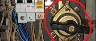
Types of pressure switch devices
There are two main versions of the device available. The pneumatic-mechanical part is identical; the difference is determined by the method of closing the contacts when the rod moves:
- Normally closed (NC). used for direct control of low and medium power motor circuits.
- Normally open (NO). The movement of the rod closes the contacts when the maximum pressure is reached. The reverse movement opens them as it decreases. The contacts are used to control a more powerful relay that starts and stops the electric motor. The circuit turns out to be more complex, but the load on the pressure switch contacts is reduced and the service life increases.
When replacing a relay, you must carefully check that its type matches the electrical circuit of the compressor. his type.
Calculation of the capacitance and voltage of the working capacitor
The calculation comes down to selecting such a capacitance so that at a rated load a circular magnetic field is provided, since at a value below or above the rated value the magnetic field changes its shape to an elliptical one, and this worsens the performance characteristics of the engine and reduces the starting torque. Engineering reference books provide a formula for calculating the capacitance of a capacitor:
Average = Isinφ/2 πf U n 2
I and sinφ – current and phase shift between voltage and current in a circuit with a rotating magnetic field without a capacitor
f- AC frequency
n - winding transformation coefficient, defined as the ratio of winding turns with and without a capacitor.
The voltage across the capacitor is calculated using the formula
Uc= U√(1+n 2 )
Uc - operating voltage of the capacitor
U - motor supply voltage
n - winding transformation ratio
The formula shows that the operating voltage of the phase-shifting capacitor is higher than the motor supply voltage.
Calculation manuals give an approximate calculation - 70-80 µF of capacitor capacity per 1 kW of electric motor power, and the capacitor voltage rating for a 220 V network is usually set at 450 V.
Also, a starting capacitor is connected in parallel to the working capacitor for the start-up period, for about three seconds, after which the relay is activated and turns off the starting capacitor. Currently, circuits with an additional starting capacitor are not used in air conditioners.
More powerful air conditioners use compressors with three-phase asynchronous motors; starting and running capacitors are not required for such motors.
Source
How to connect a 380 compressor to the network
It should be understood that the engine power with such a connection, no matter how hard you try, will drop noticeably.
Thus, a delta connection uses only 70% of the engine power, and a star connection uses even less - only 50%. In this regard, it is advisable to have a more powerful engine. When connecting the motor, be extremely careful. Take your time. When changing the circuit, turn off the power supply and discharge the capacitor with an electric lamp. Work with at least two people.
So, in any connection scheme, capacitors are used. In essence, they act as the third phase. Thanks to it, the phase to which one terminal of the capacitor is connected shifts exactly as much as necessary to simulate the third phase. Moreover, to operate the engine, one capacity is used (working), and for starting, another (starting) is used in parallel with the working one. Although this is not always necessary.
For example, for a lawn mower with a blade in the form of a sharpened blade, a 1 kW unit and only working capacitors will be sufficient, without the need for containers for starting. This is due to the fact that the engine is idling when starting and it has enough energy to spin the shaft.
If you take a circular saw, a hood or another device that puts an initial load on the shaft, then you cannot do without additional banks of capacitors for starting. Someone may say: “why not connect the maximum capacity so that there is not enough?” But it's not that simple. With such a connection, the motor will overheat and may fail. Don't risk your equipment.
Whatever the capacitance of the capacitors, their operating voltage must be at least 400V, otherwise they will not work for a long time and may explode.
Asynchronous or collector: how to distinguish
In general, you can distinguish the type of engine by a plate - a nameplate - on which its data and type are written. But this is only if it has not been repaired. After all, anything can be under the casing. So if you are not sure, it is better to determine the type yourself.
This is what a new single-phase capacitor motor looks like
How do collector motors work?
You can distinguish between asynchronous and commutator motors by their structure. The collectors must have brushes. They are located near the collector. Another mandatory attribute of this type of engine is the presence of a copper drum, divided into sections.
Such motors are produced only as single-phase ones; they are often installed in household appliances, as they allow one to obtain a large number of revolutions at the start and after acceleration. They are also convenient because they easily allow you to change the direction of rotation - you just need to change the polarity. It is also easy to organize a change in the rotation speed by changing the amplitude of the supply voltage or its cutoff angle. That is why such engines are used in most household and construction equipment.
Commutator motor structure
The disadvantages of commutator motors are high operating noise at high speeds. Remember a drill, an angle grinder, a vacuum cleaner, a washing machine, etc. The noise during their operation is decent. At low speeds, commutator motors are not so noisy (washing machine), but not all tools operate in this mode.
The second unpleasant point is that the presence of brushes and constant friction leads to the need for regular maintenance. If the current collector is not cleaned, contamination with graphite (from brushes being worn out) can cause adjacent sections in the drum to become connected and the motor simply stops working.
Asynchronous
An asynchronous motor has a stator and a rotor, and can be single or three-phase. In this article we consider connecting single-phase motors, so we will only talk about them.
Asynchronous motors are characterized by a low noise level during operation, therefore they are installed in equipment whose operating noise is critical. These are air conditioners, split systems, refrigerators.
Structure of an asynchronous motor
There are two types of single-phase asynchronous motors - bifilar (with a starting winding) and capacitor. The whole difference is that in bifilar single-phase motors the starting winding works only until the motor accelerates. Afterwards it is turned off by a special device - a centrifugal switch or a start-up relay (in refrigerators). This is necessary, since after overclocking it only reduces efficiency.
In capacitor single-phase motors, the capacitor winding runs all the time. Two windings - main and auxiliary - are shifted relative to each other by 90°. Thanks to this, you can change the direction of rotation. The capacitor on such engines is usually attached to the housing and is easy to identify by this feature.
You can more accurately determine the bifilar or capacitor motor in front of you by measuring the winding resistance. If the resistance of the auxiliary winding is twice as large (the difference can be even greater), most likely this is a bifilar motor and this auxiliary winding is a starting winding, which means that a switch or starting relay must be present in the circuit. In capacitor motors, both windings are constantly in operation and connecting a single-phase motor is possible through a regular button, toggle switch, or automatic machine.
Refrigerator electrical equipment
The unit consists of many elements, the interconnection of which contributes to the cooling of the chambers located in the internal part. We will tell you more about the key nodes in the table below.
Table 1. Components that the electrical circuit of the refrigerator includes
| Components | Purpose |
| Electric heaters | They are responsible for supplying heat to the generator in the presence of absorption refrigeration equipment, which has a specific purpose. In addition, these devices are required if there is an automatic ice removal system by heating the evaporator element. Sometimes the device is used to prevent the formation of water drops on the opening of the unit. |
| Engine | This device drives the compressor to work. |
| Wires | They connect the motor, compressor and other components to each other. |
| Paws | Required for refrigerator lighting. |
| Fans | Installed in some models with a forced air circulation system. |
Diagram of refrigeration equipment components
Refrigeration equipment does not operate in manual mode, and in order to ensure autonomous uninterrupted operation of the unit, automation is required. It is thanks to auxiliary equipment that we can change the parameters due to which the temperature remains in a certain mode. Such equipment includes the following components:
- Thermal control relay. The devices help maintain optimal temperature in the chambers of the unit.
- Start relay. Helps start the electric motor.
- Protection relay. Prevents breakdown of compressor elements as a result of high load on the electrical network.
- Devices for automatic removal of ice deposits.
Relay location
Tell me honestly - do you personally know how much electricity a refrigerator consumes per hour, per day, per month? Most likely no. In a special article we will look at this issue in detail. At the same time, we’ll see - maybe there are some ways to save money here?
Connection diagrams for single-phase asynchronous motors
With starting winding
To connect a motor with a starting winding, you will need a button in which one of the contacts opens after switching on. These opening contacts will need to be connected to the starting winding. In stores there is such a button - this is PNDS. Its middle contact closes for the holding time, and the two outer ones remain in a closed state.
Appearance of the PNVS button and the state of the contacts after the “start” button is released"
First, using measurements, we determine which winding is working and which is starting. Typically the output from the motor has three or four wires.
Consider the option with three wires. In this case, the two windings are already combined, that is, one of the wires is common. We take a tester and measure the resistance between all three pairs. The working one has the lowest resistance, the average value is the starting winding, and the highest is the common output (the resistance of two windings connected in series is measured).
If there are four pins, they ring in pairs. Find two pairs. The one with less resistance is the working one, the one with more resistance is the starting one. After this, we connect one wire from the starting and working windings, and bring out the common wire. A total of three wires remain (as in the first option):
- one from the working winding is working;
- from the starting winding;
- general.
We work further with these three wires - we use them to connect a single-phase motor.
connecting a single-phase motor
We connect all three wires to the button. It also has three contacts. Be sure to place the starting wire on the middle contact (which closes only during the start), the other two - on the outermost (arbitrary). We connect a power cable (from 220 V) to the extreme input contacts of the PVNS, connect the middle contact with a jumper to the working one (note! not to the common one). That's the whole circuit for switching on a single-phase motor with a starting winding (bifilar) through a button.
Condenser
When connecting a single-phase capacitor motor, there are options: there are three connection diagrams and all with capacitors. Without them, the engine hums, but does not start (if you connect it according to the diagram described above).
Connection diagrams for a single-phase capacitor motor
The first circuit - with a capacitor in the power supply circuit of the starting winding - starts well, but during operation the power it produces is far from rated, but much lower. The connection circuit with a capacitor in the connection circuit of the working winding gives the opposite effect: not very good performance at start-up, but good performance. Accordingly, the first circuit is used in devices with heavy starting (concrete mixers, for example), and with a working condenser - if good performance characteristics are needed.
Circuit with two capacitors
There is a third option for connecting a single-phase motor (asynchronous) - install both capacitors. It turns out something between the options described above. This scheme is implemented most often. It is in the picture above in the middle or in the photo below in more detail. When organizing this circuit, you also need a PNVS type button, which will connect the capacitor only during the start time, until the motor “accelerates”. Then two windings will remain connected, with the auxiliary winding through a capacitor.
Connecting a single-phase motor: circuit with two capacitors - working and starting
When implementing other circuits - with one capacitor - you will need a regular button, machine or toggle switch. Everything connects there simply.
Selection of capacitors
There is a rather complex formula by which you can calculate the required capacity accurately, but it is quite possible to get by with recommendations that are derived from many experiments:
- The working capacitor is taken at the rate of 70-80 uF per 1 kW of engine power;
- starting - 2-3 times more.
The operating voltage of these capacitors should be 1.5 times higher than the network voltage, that is, for a 220 volt network we take capacitors with an operating voltage of 330 V and higher. To make starting easier, look for a special capacitor for the starting circuit. They have the words Start or Starting in their markings, but you can also use regular ones.
Changing the direction of motor movement
If, after connecting, the motor works, but the shaft does not rotate in the direction you want, you can change this direction. This is done by changing the windings of the auxiliary winding. When assembling the circuit, one of the wires was fed to the button, the second was connected to the wire from the working winding and the common one was brought out. This is where you need to switch the conductors.
What it might look like in practice
Source
DIY pressure switch
With known skills, as well as the presence of a working thermostat from a decommissioned refrigerator, a pressure switch can be made independently. True, it will not have any special practical capabilities, since the ability to maintain upper pressure is limited by the strength of the rubber bellows.
Thermal relays of the KTS 011 type are most convenient for conversion into a compressor pressure switch, since they have a strictly reverse sequence of operation: when the temperature in the refrigeration chamber increases, the relay turns on, and when it decreases, it turns off.
The essence and sequence of work is as follows. After opening the cover, the location of the desired group of contacts is established, for which it is enough to ring the circuit. First, the connection between the thermal relay and the compressor is finalized. To do this, the outlet pipe, together with the control pressure gauge, is connected to the unloading valve, and the contact groups are connected to the terminals of the electric motor circuit. An adjusting screw will be found under the thermostat cover. When the compressor is turned on (the receiver should be filled to no more than 10...15% of its nominal volume), the screw is rotated sequentially, monitoring the result using the pressure gauge. To set the lower position (which determines the minimum air pressure), you will have to gradually move the face button rod. To do this, the cover is installed in place, and the adjustment is actually made blindly, since there is nowhere to connect the second pressure gauge.
- Step-down transformers 380/220
For safety reasons, the pressure adjustment range using such a thermal relay cannot be more than 1...6 atm, however, using devices with a more durable bellows, you can increase the upper range to 8...10 atm, which in most cases is quite sufficient.
After checking the functionality of the relay, the capillary tube is cut off and the refrigerant contained there is released. The end of the tube is soldered into the unloading valve.
Next, work is carried out to connect a homemade pressure switch to the compressor control circuit: using a nut, the relay is attached to the control board, a thread is made on the rod, and a lock nut is screwed on, by rotating which you can adjust the limits of air pressure change.
Considering that the contact group of any thermal relay from a refrigerator is designed for fairly high currents, in this way it is possible to switch circuits of significant power, including secondary compressor motor control circuits.
Where you should definitely start connecting the engine: 2 important time-tested points
Before turning on any electric motor for the first time, it is necessary to clarify its structure: the design of the stator and rotor, the condition of the bearings.
From my own and other people’s experience, I can assure you that it is easier to loosen a few nuts, inspect the internal structure, identify defects at the initial stage and eliminate them, than to deal with complex repairs that could have been prevented after starting a short operation.
Important Warning
Novice electricians quite often create engine malfunctions themselves, violating the technology for disassembling it, working with an ordinary hammer: they break the edges of the shaft.
To preserve the structure of parts without damaging them, it is necessary to use a special electric motor bearing puller.
In the most extreme case, when it is not available, blows with a hammer are applied through thick plates of soft metal (copper, aluminum) or dense dry wood (apple tree, pear tree, oak).
How bearing condition affects engine performance
Any asynchronous electric motor (IM) has a rotor with squirrel-cage windings. A current is induced in them, creating a magnetic flux that interacts with the rotating magnetic field of the stator, which is its source of movement.
The rotor inside the housing is mounted on bearings. Their condition greatly affects the quality of rotation. They are designed to ensure easy sliding of the shaft without backlash or runout. Any violations are unacceptable.
Safety precautions
Although a drill press is easy to connect and use, working with it can be dangerous without proper safety precautions. Among them it is worth highlighting the following:
- Perform any repair or cleaning work only with the engine power off;
- use protective clothing and glasses to protect yourself from flying chips, dust, drops of cutting fluid, and parts of the drill that break;
- hide long hair under a hat, avoid working with gloves - if they get wrapped around rotating elements, they can lead to serious injuries;
- Before starting work, carefully check all moving parts of the machine for defects and damage. If they are detected, it is prohibited to use the device.
To find out more about how to connect a drilling machine, contact Metaltool and they will answer your questions in detail.
Source
Connection diagram for an asynchronous motor with a starting winding: assembly sequence
For example, we have determined that there are four or three wires coming out of the stator. We call up the active resistance between them with an ohmmeter and determine the starting and operating windings.
Let’s assume that four wires have two pairs with resistances of 6 and 12 ohms connected to each other. Let's randomly twist one wire from each winding, designate this place as a “common wire” and get a measurement of 6, 12, 18 Ohms between the three terminals.
I marked the beginnings of the windings with dots on this diagram. For now, ignore this question. But, you will need to return to it further when the need arises to reverse.
The chain between the common terminal and the lower resistance 6Ω will be the main one, and the larger 12Ω will be the auxiliary, starting winding. Connecting them in series will show a total result of 18 ohms.
We mark these 3 ends with markings that are already clear to us:
Next we need a PNVS button, specially designed for starting single-phase asynchronous motors. Its electrical circuit is represented by three closing contacts.
But, it has an important difference from the start button of three-phase NVD electric motors: its middle contact is made with self-return, and not fixed when pressed.
This means that when the button is pressed, all three contacts are closed and held in that position. But, when you release your hand, the two outer contacts remain closed, and the middle one returns under the action of the spring to the open state.
We connect this button and the terminals for the output of the stator windings from the electric motor with a three-core cable so that the starting winding contact goes to the middle contact of the PNVS. We connect pins P and P to its outermost contacts and mark them.
On the back side of the button, between the contacts of the starting and working windings, we rigidly mount a jumper. We connect a 220 volt household power cable with a plug for installation in a socket to it and the second outer contact.
What can be redone
Low-power 380 Volt electric motors are suitable for conversion: up to 3 kW. Theoretically, powerful motors are also reconnected. But this will additionally entail the installation of a separate circuit breaker in the electrical panel and special wiring. And this work becomes meaningless if it suddenly turns out that the input cable cannot carry such a load.
Read also: Btb10 800bw how to check with a tester
Even if your network carries high loads, and you managed to convert a 3 kW motor from 380 to 220 Volts, you will be upset the first time you put it into operation. The launch will be difficult. You will decide that the work was in vain. Therefore, if you redo it, then it will be low-power models.
Wiring diagram for an asynchronous motor with capacitor start: 3 technologies
The stator with windings for starting from capacitors has approximately the same design as discussed above. It is difficult to distinguish it by appearance and simple measurements with a multimeter, although the windings may have equal resistance.
Refer to the nameplate and table from Aliyev’s book. You can try to connect such an electric motor using a circuit with a PNVS button, but it will not spin up.
It will not have enough starting torque from the auxiliary winding. It will hum and twitch, but will not reach the rotation mode. Here you need to assemble a different capacitor starting circuit.
The 2 ends of different windings are connected to a common terminal O. A household voltage of 220 volts is supplied to it and the second end of the working winding through an AB switching device.
The capacitor is connected to the terminals of the starting and operating windings.
As a switching device, you can use a double circuit breaker, a switch, NVD or NVDS type buttons.
- the main winding operates directly from 220 V;
- auxiliary - only through the capacitor.
This circuit is used for easy starting of capacitor electric motors that are put into operation without heavy load on the drive, for example, fans, sanders.
If, at the moment of starting, it is necessary to simultaneously spin the belt drive, gear mechanism of the gearbox or other heavy drive, then a starting capacitor is added to the circuit, which increases the starting torque.
It is convenient to describe the operating principle of such a scheme using the same PVS button.
Its self-resetting contact is connected to the auxiliary winding through an additional starting capacitor Sp. The second end of its plate is connected to terminal P and working capacity Cp.
An additional capacitor at the moment of starting an electric motor with a heavy drive helps it quickly reach its rated rotation speed, and then simply turns off so as not to create overheating of the stator.
This circuit is fraught with one danger associated with long-term storage of a capacitive charge by the starting capacitor after removing power 220 when the electric motor is turned off.
If the worker is not careful or careless, the discharge current can pass through the human body. Therefore, the charged capacity must be discharged.
In the scheme under consideration, after removing the voltage and pulling out the plug and power cord from the socket, this can be done by briefly turning on the PVS button. Then the capacitance Sp will begin to discharge through the starting winding of the motor.
However, not all people do this for various reasons. Therefore, it is recommended to install two additional resistors in the starting circuit.
Resistance Rр is selected with a nominal value of about 300÷500 Ohms of several watts. Its task is to discharge the auxiliary capacitance Sp after removing the supply voltage.
The Ro resistor is low-resistance and powerful and acts as a current-limiting resistance.
Where can I get the values of the main and auxiliary capacitors?
The fact is that the factory determines the value of the starting and operating capacitance for capacitor starting of a single-phase IM individually for each model and indicates this value in the passport.
There are simply no separate formulas for calculating how it is done for capacitor starting of a three-phase motor in a single-phase network using star or delta circuits.
You will need to look for factory recommendations or experiment during the setup process with different containers, choosing the most optimal option.
The owner of the video “IV I'm Interested” shows how to optimally configure the parameters of a capacitor motor starting circuit.
Description of the main elements of the refrigerator
Each piece of equipment participates in the overall heat exchange. It is thanks to the correct functioning of the devices that a constant and sub-zero temperature is maintained in the chambers of the unit. In order to understand how this happens, it is necessary to take a closer look at the operation of each element.
Motor-compressor: functional purpose
This is the main unit of the device, which ensures smooth circulation of the refrigerant in the heat exchange system. Up to two compressors are installed in the unit, depending on the purpose.
The main function of the motor is to move the compressor. This means that it is responsible for the process of converting electrical energy into movement of the compressor. Improved models of devices are equipped with piston compressors, inside of which there is an engine. Thus, the possibility of loss of freon is eliminated, so the units are less susceptible to breakdowns.
Engine-compressor
To reduce vibration during compressor operation, internal or external suspension is used. The first option is popular because it better eliminates vibration.
What is a capacitor needed for?
This is an element of heat exchange. Thus, it is necessary to remove heat from freon, which evaporates and heats up. In standard devices, the capacitor is located on the rear wall, it is a type of zigzag device.
If we are talking about industrial refrigeration equipment, then instead of a condenser, a radiator is installed here. It is installed together with a ventilation system for quick heat transfer. The main thing is that the condenser always remains cold, then the refrigerator will work without interruption.
Condenser - zigzag device on the rear wall of the unit
Features of the evaporator
This is also a component involved in heat exchange. It is only necessary for the purpose of cooling freon. It turns out that the refrigerant boils in the system, due to which heat is absorbed.
Capillary pipeline
This component is located between the condensate and the evaporator. On average, the length of this pipeline is 150-300 centimeters. This device helps create normal refrigerant pressure.
Capillary tube
Filter drier for refrigerant cleaning
This component is installed near the entrance to the capillary pipeline. It has the following functional purpose:
- prevents pipeline contamination;
- prevents freezing of the place at the exit from the tube;
- absorbs excess liquid from the refrigerant.
Filter drier for refrigerant cleaning
Boiler: compressor protection
This is a recess that is located between the compressor and the evaporator element. The container is required so that the refrigerant boils and does not reach the compressor in its original form. Otherwise, the equipment will quickly fail. As a rule, such a device is fixed in the unit chamber.
The boiler is located in the center
How does the cooling process occur?
We looked at the components that are installed in the refrigerator. Next, you need to familiarize yourself with the features of the interaction of these components, due to which cooling occurs.
A standard refrigerator without additional functions works as follows:
- With the help of a compressor motor, refrigerant gas is generated from the evaporator. Next, the gas is compressed by a compressor, and then through a filter it moves to the condenser.
- After compression, the liquid refrigerant becomes hot. Only in the condenser is it cooled, which is why it becomes liquid.
- Liquid freon is under pressure from the compressor. From the condenser, the substance moves through the pipeline to the evaporator. There the refrigerant is converted back into gas, but a heat source is required for this to happen. Freon absorbs this heat on the walls of the refrigeration equipment. Due to this process, a subzero temperature is observed inside the device, and the refrigerant turns into gas.
- This movement of freon will continue until a certain temperature is reached. Only then will the temperature controller turn off the electrical circuit, causing the compressor to stop functioning.
- Due to the lack of cold, the temperature inside the device will increase. After which the thermal regulator will close the contacts, and the relay will turn on the motor.
It turns out that the process of operation of the refrigerator is based on the transformation of the refrigerant from liquid to gas and back. This process occurs automatically.
Features of the functioning of refrigerator components
Possible malfunctions of the device
Several malfunctions characteristic of pressure switches are noted. In most cases, they are simply replaced with new devices. However, there are minor problems that you can fix yourself without the help of a repairman.
The most common malfunction is characterized by air leakage from the relay when the receiver is turned on. In this case, the culprit may be the start valve. It is enough to replace the gasket and the problem will be eliminated.
Frequent starting of the compressor indicates loosening and displacement of the adjusting bolts. Here you will need to double-check the threshold for turning on and off the relay and adjust them according to the instructions in the previous section.
Complete set of compressor automation unit
The relay design is a small-sized block equipped with receiving pipes, a sensing element (spring) and a membrane. Mandatory subassemblies include an unloading valve and a mechanical switch.
The pressure switch sensing unit is made up of a spring mechanism, the compression force of which is changed by a screw. According to the factory standardized settings, the elasticity coefficient is set to a pressure in the pneumatic chain of 4-6 at, as reported in the instructions for the device.
The degree of rigidity and flexibility of the spring elements is subject to the temperature of the environment, therefore absolutely all models of industrial devices are designed for stable operation in an environment from -5 to +80 ºC.
The reservoir membrane is connected to the relay switch. During movement, it turns the pressure switch on and off.
The unloading element is located between the ejector check valve and the compression block. If the motor drive stops working, the unloading section is activated, through which excess pressure (up to 2 atm) is released from the piston compartment.
With further start or acceleration of the electric motor, a pressure is created that closes the valve. This prevents overloading of the drive and simplifies starting the device in switched off mode.
There is an unloading system with a time interval of activation. The mechanism remains in the open position when the engine starts for a specified period. This range is enough for the engine to achieve maximum torque.
A mechanical switch is required to start and stop the automatic system options. As a rule, it has two positions: “on.” and "off". The first mode turns on the drive and the compressor operates according to the established automatic principle. The second one prevents accidental starting of the engine, even when the pressure in the pneumatic system is low.
Safety in industrial structures must be at a high level. For these purposes, the compressor regulator is equipped with a safety valve. This ensures system protection in case of incorrect relay operation.
In emergency situations, when the pressure level is higher than the permissible norm, and the telepressostat does not work, the safety unit comes into operation and vents the air. Safety valves in heating systems operate according to a similar scheme, the operating principles and devices of which are described in the article we recommend.
Optionally, a thermal relay can be used as additional protective equipment in the review device. With its help, the strength of the supply current is monitored for timely disconnection from the network when parameters increase.
To avoid burnout of the motor windings, the power is turned off. The nominal values are set using a special control device.
Functionality check
How to check engine performance by visual inspection?
The following are defects that indicate possible problems with the engine; they could be caused by improper operation or overload:
- Broken support or mounting gaps.
- in the middle of the engine has darkened (indicates overheating).
- through cracks in the housing.
To check the performance of the engine, you should first turn it on for 1 minute, and then let it run for about 15 minutes.
If after this the engine is hot, then:
- Perhaps the bearings are dirty, jammed, or simply worn out.
- The reason may be that the capacitor capacitance is too high.
Disconnect the capacitor and start the motor manually: if it stops heating, you need to reduce the capacitor capacitance.