A circuit breaker is a convenient and practical replacement for fuses, which not only has higher tripping accuracy, but can also be used a large number of times. How to properly connect a machine is a question that not only novice electricians, but also every self-respecting owner of a private house or apartment should understand. And this article will not only tell you how to install an automatic or differential switch, but will also introduce readers to the variety of switching equipment and the operating principle of package switches.
Design of a standard circuit breaker
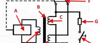
For example, we will use the BA47-29 series switch as the most popular switching device with an affordable pricing policy. Before you learn how to properly connect a circuit breaker to a single-phase network, you need to consider its design.
The BA47-29 series circuit breaker consists of the following elements:
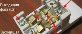
- A copper terminal connected to a fixed power contact. Most often, the supply wire is installed exactly in this place.
- The movable contact, which makes the switching, and the copper stranded conductor, has a sufficiently large cross-section.
- Arc chamber.
- A special thin plate with a hole through which gases formed after the arc escape.
- An electromagnetic release, presented in the form of a simple coil. The stranded conductor from the moving contact is soldered to the coil.
- Plastic, fully dielectric handle.
- A bimetallic plate that acts as a thermal release. The plate is located immediately behind the reel.
- A special screw for adjusting the bimetallic plate. The screw is not installed on all models, and adjustment is made at the manufacturer.
- The lower copper terminal, from which the conductor goes directly to the consumer.
A three-phase machine has a similar design, but instead of one terminal, it uses three, isolated from each other.
What is a machine gun
- Cocking handle. Brings the device into working condition. If necessary, you can also turn off the machine yourself by moving the lever to the bottom.
- Enabling mechanism. Located inside the case.
- Contacts. They are intended to close and open a circuit.
- Clamps. Connect to a device that provides protection.
- Mechanisms. This is a temperature-triggered release plate. Having a bimetallic base. Many machine designs have a current adjustment screw.
- Arcing chamber. It may be located inside, in different poles of the machine.
Enter from above or below
A very important question that worries both many electricians and just home craftsmen: how to connect the machine, from above or from below? To answer this, you will have to refer to the regulatory documentation, namely, the Rules for the Construction of Electrical Installations.
Paragraph 3.1.6 states that the machine should be connected to the electrical network from the side of the device on which the fixed contact is located. This means that the voltage in a single-phase or three-phase network must be on the side of the switch that does not break the electrical circuit. Paragraph 3.1.6 applies to many types of switching equipment. This can be not only a single-contact, but also a two-pole or three-phase circuit breaker, as well as a differential package or RCD.
You can find out the location of this contact only by disassembling the bag, which is not very convenient every time you replace it in the apartment. But the design of all machines is almost the same, so you should find out where the fixed contact is located on only one switch. And it is located on top, so the connection of a single-pole or two-pole circuit breaker must also be done from above.
If you happen to have a packet from an unknown manufacturer in your hands, then just look at its body, or more precisely, the front panel. In this place, most often all the necessary information is placed on the machine, such as the model, accuracy class, and connection diagram of the circuit breaker with the exact location of the moving and fixed contacts.
Conclusion: the connection of the circuit breaker to the electrical network must be done from above. This is what the regulations say, which help avoid unnecessary confusion. But if you look from the technical side: is the difference in connecting the power cable significant? Answer: no, it does not matter at all from which side the operating voltage is supplied to the package. The device will work properly both with connections from above and from below.
Currently, I have chosen electrical panels and devices from ABB.
But knowledge of modular and panel products from Schneider Electric, Legrand, Hager allows me to assemble electrical panels from components from any manufacturer. Therefore, when choosing a company, I always go to meet the customer of the shield.
But it should be noted that the prices from these manufacturers are almost the same. The only difference is different series of devices, but even if they are similar in parameters, they are also the same.
Below I will give a comparative calculation of the cost of an electrical panel of different series of ABB and Schneider Electric for one of the orders (the calculation is already outdated, but is still relevant).
Comparison of prices for automatic machines, RCDs, switches from ABB and Schneider Electric.
Electrical panels, at the request of the customer, can be equipped with various additional “wants” and protections: light indicators, digital voltmeters, contactors with on/off switching of all or part of the load, timers (time relays) for turning on the load according to a schedule, voltage control relays, etc.
The sequence of correct connection of the machine
Before you learn how to install the machine correctly, you need to stock up on the most necessary tools. If in the future electrical installation turns into the main type of income, then the following list of tools will not be enough.
- Phillips and flat head screwdriver. Preferably dielectric.
- Indicator screwdriver.
- Monter's knife.
- Screwdriver.
Professional craftsmen also have crimping pliers in their bins, and instead of a fitter's knife, they most often use a special knife for stripping insulation. This is not only more convenient, but also allows you to get the job done faster.
Step #1: DIN Rail Mounting
Do-it-yourself installation of a DIN rail in a panel takes 10-15 minutes. The main condition for fast work is the presence of a good screwdriver, preferably with an autonomous battery.
There are three main types of DIN rails:
- Ω-type. Products of this form are considered the most common, and any circuit diagram for connecting machines in a panel implies the presence of such a product.
- C-type. The ends of the product are bent inward.
- G-type. This rail is similar to the C-shape, but with only one shorter side.
The sequence of installing a DIN rail in an electrical panel:
- Mark the location of the DIN rail in the panel.
- Place the DIN rails on the metal surface and secure them on one side using tex, a special self-tapping screw.
- Align the rail using a building level and secure it on the other side.
If necessary, the DIN rail can be cut to any length, but this product is mainly sold in 2-meter lengths.
Step No. 2: installing the machine on a DIN rail
The simplest procedure in the entire topic “How to connect a machine in a panel.” On each circuit breaker, on one side (usually the bottom) there is a special plastic latch. It must be removed, installed on the DIN rail and pressed until it clicks. After this, the circuit breaker will be securely fixed and you can proceed to connecting it.
Step No. 3: connecting the machine to the network
To find out how to correctly connect the machine in the electrical panel, you must first read the paragraph, which discusses in detail the question of whether the package should be connected from below or from above. As the regulatory documents say, voltage must be applied to the fixed contact of the switching device, and most often this contact is located on top.
Before connecting a single-pole or double-pole circuit breaker to the network, it is necessary to remove the insulation from the wire, crimp it together with the tip and make sure, using an indicator screwdriver, that there is no voltage coming to the packet.
After this, insert the securely pressed tip into the standard connection point of the machine and clamp the connection point using a bolt specially provided by the manufacturers. Check the quality of the connection by moving the wire without applying unnecessary force. If the installation is done correctly, then the machine can be turned on and checked whether everything is working in the apartment.
Panel, counter, machines and socket - Community "Garage Affairs" on DRIVE2
Since there was no light at all in the garage, initially it was necessary to install a meter and run the wiring to it. As always, my luck at the “MIRACLE of the Masters” was in action.
An electrician from a cooperative, a rather strange man, considering that he lives in a cooperative, on the second floor of his garage. Anyway.
I gave him a machine meter and a socket with a panel with the agreement that he would arrange all the equipment into a panel, and the next day everything would be ready in my garage (Wednesday). I asked for 1000 rubles.
Important
We agreed and then off we went, either busy, sick, or some other crap! Due to being busy at work, I couldn’t go and give him a kick for a week. And so on Friday evening I went to see this ghoul, chased this asshole all over the garage, saying that the horse lay down (where did he find it in the garages?!), after which he took everything he bought and went home.
Early in the morning I sat down to assemble the shield myself, although I was undertaking to do it for the first time, I was completely confident that I would do it perfectly and it seems that it turned out that way)
What we have: 1. Double circuit breaker for 25A (used as a switch), installed before the meter.2. Two single 25A circuit breakers, one for sockets in the garage, the other for an socket in the panel.3. One single 16A circuit breaker for lighting in the garage.4. Actually the shield itself (for some reason I visually liked the metal one).5.
Mercury meter 201.5.6. Two zero buses, one isolated, is used as a general phase distribution and the second, respectively, for its intended purpose for ZERO.7. 1 meter of copper cable with section 4.8. 7 meters of AVVG aluminum cable with a cross-section of 6 (the wiring to the garage is very old and made of aluminum).9. Corrugation (got a bunch for free).10.
Fasteners for corrugated walls.
11. Self-tapping screws with a dowel for fastening.
And now about the main thing!) I covered a piece of the metal plate on which I actually installed the elements with a film under polished aluminum) because there was nothing better to do) and then away we went.
Layout
We twist, twirl, bend the wires and do everything according to Feng Shui.
An hour and a half later, all the elements were installed as desired and everything was very neat!
On Saturday afternoon I went to the cooperative and kicked the chairman to force that asshole to install the assembled panel on the wall and connect it to the general network. In my understanding, installing a meter means twisting the wires with the street ones and putting a seal.
Common mistakes when connecting the machine to the network
Unfortunately, even experienced electricians with many years of experience behind them make minor mistakes at first glance, which can later lead to very big problems. To avoid such errors when connecting the input machine, you need to familiarize yourself with them in advance. Prevent a problem before it occurs.
Wire clamp with insulation
A very popular mistake that is made mainly due to inattention. The main difficulty is that a visual inspection may not show any results: all the machines in the electrical panel are intact, the wires are not damaged, and there is still no light in the apartment.
And the problem is the incorrect connection of the power cable, or rather, too small a section of the removed insulation. The technician removes a small piece of insulation from the wire, places it in a fixed contact and tightens the bolt. The standard connection of the machines is in the panel and everything is done according to the rules. But only the contact could get not to the conductive core itself, but to the insulation. Result: poor contact, which will lead either to a burnt-out machine or to a lack of light in the apartment. It may take a long time to determine the problem and reconnect the cable to the packager.
Therefore, in order to avoid such consequences, the connection of a single-pole or two-pole machine must be made with a high-quality stripped wire. And it’s okay if the cleaned core peeks out a little from the insertion point.
Connecting several wires of different sections to the machine
Before installing circuit breakers, you need to know how to do it correctly. And often in apartment panels you can see several wires that are installed in one regular place for connection. And it’s good if it’s 2 wires, but many craftsmen try to connect 3 or more wires of different sections to the machine. After which the life of the circuit breaker is reduced several times.
If the wires to the machine have different cross-sections, then when the contact is tightened, the one with the larger cross-section will be well secured. A cable with a smaller diameter will “walk” freely in the package’s seat. The result will be poor contact, which will soon lead to complete burnout of the connection point of the machine.
Therefore, it is best to connect the machines to each other with a single piece of wire, stripped only in places of direct contact with the circuit breaker. This piece of wire is also called a comb bus, which you can make yourself.
Connecting several machines to a meter or to each other can also be done using special crimp terminals NSHVI-2. These are consumable products into which 2 wires can be pulled at once. The only downside to this installation option is the need to purchase special crimping pliers.
Incorrect formation of core ends
How to connect circuit breakers in a panel is already known and the main errors have been discussed, but even such a minor error as incorrect formation of the end of the conductor can lead to the need to replace the switch.
The sequence of connecting cables to machines is standard: strip the core to the required length, guide the wire into the seat and tighten the lock, which is most often made for a Phillips screwdriver. They try to make the end of the conductor straight. But in order to improve contact at the junction of the wire and the copper plate of the machine, a U-shaped bend must be made at the end of the cable.
This is the most reliable advice on the question of how to properly connect machines to the input power supply or apartment wiring. The U-shaped bend allows you to increase the area of contact between the wire and the copper plate of the bag, and, accordingly, improve the quality of contact. The rest of the work will be done by the ribbed surface of the slots for connecting the machines.
Connecting a stranded wire to a machine without special ends
How to connect a circuit breaker, single-phase or two-phase, using a stranded cable? Answer: only using special crimp lugs such as NShV or NShVI.
Many electricians do not bother themselves with high matters and make this connection in two standard ways:
- Tin the end of the copper wire.
- Without using any contact materials at all, simply squeezing the wire with pliers.
Both the first and second methods are incorrect, and will soon only lead to the replacement of the machine. And if everything is clear with the second point, then cable soldering, on the contrary, is encouraged by all technical and regulatory documentation. Unfortunately, not always. Even a high-quality tinned wire under voltage gradually begins to “drain”, and in order to prevent contact deterioration, it should be constantly checked and tightened. Therefore, soldering is not practical in this case.
It is best to purchase special crimping pliers and tips NShV or NShVI. All that remains is to strip the input cable, put a tip on it and crimp it using pliers. After this, the carefully crimped stranded core can be secured in the machine and there is no need to check the quality of the connection every few months.
With press jaws, installing automatic machines will become a quick, and most importantly, high-quality procedure. This tool is especially useful when the electrician profession is a constant source of income.
Which wire to use for outdoor wiring: the best options
We smoothly approached the main question of which wire to use for external wiring in order to be confident in its reliability and ability to withstand negative natural influences. The main requirements for such products are combustion resistance, strength and non-hygroscopicity.
The most popular types include:
SIP is an outdoor power cable capable of conducting voltages up to 1000 V. Structurally, the product is a group of wires with individual insulation and aluminum conductors. Such products have their own subtypes (SIP -1, 2, 3, and so on) and are produced in many countries around the world. The main feature is the black insulation of the wires. The use of such a cable guarantees greater reliability during aerial installation and reduces installation costs. An additional advantage is its compactness, which allows the cable to be used even in conditions of limited space.
AVBbShv is a product based on a group of wires with aluminum cores combined under one armored sheath. One of the cable types is VBBShV - a version with copper wires. A special feature is the possibility of laying in the ground without the use of additional protection and resistance to mechanical stress. Main characteristics:
- The presence of steel tape in the shell.
- The wire insulation is made in different colors for ease of dialing and connection.
- The outer shell is black.
- Resistant to moisture and temperature changes.
- Resource - 30 years.
Due to the presence of armor, cable products of this type are characterized by increased rigidity, which creates additional problems during the installation process.
NYY is a cable characterized by versatility and reliability in operation. May have copper or aluminum conductors. This product is increasingly used for external wiring in the ground or in the air, as well as for connecting electrical receivers indoors. Main characteristics:
- Resistant to water and fire.
- Compliance with international standards.
- Availability of multi-colored wire insulation.
- Convenience of organizing outdoor wiring.
- The outer shell is black PVC plastic.
- Resistant to temperature changes.
- Resource - 30 years.
This cable is produced in many factories due to its versatility and reliability. The main competitor of the product is considered to be the VBBShV cable, which was mentioned above.
NYM is a reliable cable that is actively used in production and outdoor wiring. Its peculiarity lies in its versatility and ability to operate in various conditions. Characteristics:
- Compliance with the standards of the German Electrical Engineers Union.
- Heat resistance and ability to operate over a wide temperature range.
- Non-hygroscopic and durable, which allows the product to be laid in concrete or in a layer of plaster.
- The cross-section is round, the color is gray.
- Fire resistance.
When installing wiring outdoors using NYM, protection from sunlight is recommended. Such cable products are produced at many factories located in Europe and Russia. Some manufacturers produce cables according to individual specifications, but such products have a lower price and, accordingly, worse quality. The use of such cables for external wiring is not recommended.
How to properly connect SIP to a machine
SIP is a self-supporting insulated wire that is used almost everywhere to introduce electricity into the house. Therefore, the question of how to connect a SIP to a single-pole circuit breaker is very relevant.
Firstly, the SIP is made of aluminum, and the contact plate of the circuit breaker is made of copper. The correct connection of copper and aluminum requires the use of a special crimp sleeve, and in the case of subsequent connection to the machine, a sleeved tip, at the point of contact of which there is a special copper coating. It is impossible to connect a SIP to a machine without such a tip, since aluminum tends to oxidize, causing the quality of the contact to be lost. And poor contact is the first cause of fire.
The sequence of connecting the SIP to the machine:
- Strip the cable.
- Place a sleeved tip on the open core. It is important to put it on tightly and so that the insulation begins immediately behind the sleeve.
- Using a hydraulic press, compress the sleeve in two places.
- Place a heat-shrink tube over the open part of the sleeve and heat it with a hair dryer.
- Insert the tip into the machine and tighten the contact properly.
This installation method is the same for both single-phase and three-phase machines; you just need more tips.
Drawing up an electrical panel diagram
An important step in installing an electrical panel is creating its diagram. There are several explanations for this. Let's say, if you plan to repair or modernize the wiring in your apartment in the future, using the diagram you can quickly establish what each machine and part in the panel is responsible for. You will also need the diagram when accepting work as an electrician. In addition, connecting wires with such a diagram on hand is much easier. You can either draw it manually or in specialized programs, and then print it.
The electrical circuit is created in several stages. The first step is to find out what kind of electrical system is in the house, then divide all points of electricity consumption into several categories. After this, based on the existing data, a shield diagram is created
It is extremely important that the diagram used symbols, which are described in detail in GOST 21.614 “Conventional graphic images of electrical equipment and wiring in the original”
So, as mentioned above, all work begins with determining the power supply and grounding system in the apartment, since the connection of the panel will depend on this. You can find out by looking at the sign on the floor or by going to the housing office. Often, three systems TN-C, TN-S, TN-C-S are installed in residential buildings.
It is worth immediately noting that the first system was created according to old GOST standards and was used in houses that were built before 1998. The TN-C system is represented by two-core copper or aluminum wiring. A three-phase cable (L) with one conductor PEN, in which ground and neutral were combined, went to the floor distribution board. The last two systems are used in modern homes. A three-core copper wire is laid in the apartment, and a cable with three phases (L), neutral (N) and PE ground (S) is connected to the switchboard.
Which is correct: machine before or after the counter
To answer this question, you should also refer to the PUE, namely to paragraph 1.5.36, which states that for the safe installation and replacement of meters in networks up to 380 V, a circuit breaker must be installed in front of them (at a distance of no more than 10 m) . And this same machine in front of the meter acts as a switching device to disconnect the entire apartment or house, and its nominal values must be appropriate.
The number of machines after the meter is determined directly by the owner of the apartment or house, or by the design organization performing the installation of electrical wiring. There are such electrical panels, the number of devices in which reaches 40-50 pieces, and this is without RCDs and differential circuit breakers. When installing an introductory machine before the meter, the same one can be installed after it. This will not affect the operation of the metering device in any way.
Important! Only representatives of energy supervision authorities can connect the electric meter to the network. Therefore, before connecting an apartment, you should find such an organization in your city and formally call a specialist.
Choosing the right wire for high-quality electrical panel assembly
Reading time: 3 minutes No time?
There is quite a lot of information on the Internet on assembling electrical distribution panels with your own hands. However, it is not enough to learn how to do this work. It is much more important to understand how to choose the right wire for high-quality assembly of an electrical panel and connection of protective automation. Today's article will talk about exactly that.
After all, it is vitally important for a home craftsman who is planning to do electrical installation in his apartment or private house to understand what features a particular material for making or modifying a cable has
Choosing a wire modification and its cross-section is a very important task.
Read in the article
How to install an RCD: before or after the machine
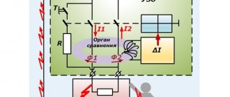
The residual current device is a very useful switching device that requires correct installation, otherwise its operation may be unstable. If the installation is carried out incorrectly, then at the first short circuit in the apartment you will need to replace the RCD, which is an order of magnitude higher in cost than any circuit breaker.
There is no particular difference whether the RCD will be located before or after the machine. But the issue can be considered from a practical perspective. Any residual current device does not have protection against short circuit currents, and if you install it without a circuit breaker, the consequences can be very different, including damage to the device.
Therefore, it is best to install an RCD immediately after the introductory machine, but before the packetizer, the line from which will go directly to the consumer. This will provide reliable protection of the circuit from short circuits, and users from the unwanted action of operating potential when a phase wire gets into contact with the housing of a household appliance.
Purpose of boxes for machines
Plastic and metal boxes perform the same function as distribution boards - they organize the operation of electrical equipment and serve for the electrical installation of protective devices. In the specialized literature you can find other names: box, box, shield, panel.
The main “filling” for filling the box is made up of electric machines, however, other protective devices - RCDs and difautomatic devices - can be located next to them.
There are no products for sale with pre-installed equipment. Low-voltage boxes are sold empty, and automatic protection devices are selected taking into account the characteristics of the network and installed according to the selected scheme
Large boxes contain indicators, switches, timers, differential relays. But to equip the network of a private house or one apartment, installation of additional equipment is not necessary.
If, in addition to protective equipment, an electricity meter is installed inside the box, then the panel goes from the distribution category to the metering and distribution category
Boxes are installed in apartments, on floor areas, as well as on the street, if it is necessary to connect a private home to the power supply line. They are varied in design, assembly and functions.
How to properly connect a differential machine
Of all types of switching devices, a differential automatic machine is considered the most practical, but at the same time expensive. It combines the functions of a circuit breaker and a residual current device. Such a device is not installed like a regular package, but requires a slightly different approach.
The differential machine is connected as follows:
- The neutral wire is installed in the upper clamping contact.
- A phase wire is installed in the right clamping contact.
It should be immediately clarified that the contact locations can be changed, but the manufacturer marks the connection sockets with the appropriate letters. And under the operating or non-working position switch there should be a special button to check the functionality of the device.
The neutral wire that passes through the differential circuit breaker cannot be connected to other circuit breakers. With this installation, the device will constantly turn off, since the currents flowing through the conductor are completely different.
There are schemes in which a differential machine is connected to a group of packagers, while in other schemes such devices are used exclusively for one consumer. When designing wiring, it is better to choose the second option, in which, when the device is triggered, only one consumer will be de-energized, and not a whole group of machines.
Wire for assembling an electrical panel: brand, cross-section, nuances of choice
Work related to electricity requires a high level of training of the master. An emergency situation can be created by either low-quality components or insufficient education of the electrician, or incorrectly selected wires.
General principles for wiring in the panel
The switchboard contains all the equipment and mechanisms for connecting consumers to electricity.
For its proper operation and safety, it is important to use suitable wires and high-quality parts, because due to a malfunction, users may be left without light, or a fire may even start. The function of conductors in an electrical panel is to connect controllers, indicators and other devices
The entire panel, including the metal casing, must be reliably grounded. Ideally, you should also put a lock on it so that unauthorized people do not have access to the equipment.
The function of conductors in an electrical panel is to connect controllers, indicators and other devices. The entire panel, including the metal casing, must be reliably grounded. Ideally, you should also put a lock on it so that unauthorized people do not have access to the equipment.
The connection must be made in such a way that the connecting wires do not sag. To do this, you need to carefully measure the distance between the connection elements and cut off a few centimeters more so that they can be inserted into the terminals. You cannot save on this, and if the calculations turn out to be incorrect, it is better to repeat the operation.
How to choose wire metal
Electrical panels must use copper wires. This is because this metal lends itself well to bending and does not break. Aluminum will be difficult to bend, and even modern wires made of this material can withstand no more than a few bends and then simply break.
Everything in the shield must be tightly installed, so the wire must be as flexible as possible.
Single-core and stranded wires
The type of conductor is an indicator of the flexibility of the wires. The advantage of monocore is that they can be immediately inserted into the clamps, but some of them bend poorly, which causes difficulties. Stranded ones are much more flexible and easier to work with, but their ends must be pressed together with a special tip, and only then used.
Section
The cross section must be selected in relation to the current that will pass through the panel. However, if upon purchase the wire is in doubt, there is no quality certificate for it, or there is uncertainty about the reliability of the information about the cross-section, you need to take it with a reserve. For example, not 6 mm, but 10.
The most suitable brands of wires
Both domestic and imported materials are used for installation. Among Russian products, we can recommend PV-1 (single-wire), or PV-3, PV-4 (multi-wire). Of the foreign analogues, H05VK and H07VK are perfect for such work.
Color coding and jumpers of machines
The color of the shell also plays an important role.
You need to pay attention to this, because black, red, brown, purple, gray, pink, orange, white and turquoise are phase
The yellow-green shell indicates that this is a protective or zero protective shell that can be used for grounding. If blue is added to this color, it is a combined working and zero color.
If the wire is just blue, it means the conductor is zero working or average.
Jumpers are installed between adjacent machines. For connection, you can use both single-core and multi-core materials, but the former will still be more convenient - they do not need to be pressed.
To make the right choice of components, you need to take into account the material and calculate the amount of voltage that will pass through the conductor. The cross section and even the color of the shell play an important role. The wrong choice of material can lead to many disastrous consequences, so it is best to delegate the task of creating the wiring to a master who can confirm his professionalism.
Connecting two-pole and three-pole circuit breakers
The principle of connecting two-pole and three-pole circuit breakers is exactly the same as in the case of a single-phase packet switch. And if the question arises of how to connect a three-phase machine, then you should perform all the operations that were carried out with a device designed for a single-phase network.
In the same way, strip the wires, crimp them using lugs and a press, and install each wire on the corresponding fixed terminal, and then clamp it with a screw clamp. If a three-pole circuit breaker is installed in a production facility where further connection of asynchronous or synchronous motors is planned, then after installation the phase rotation should be checked using a special device - a phase indicator. If the phases are reversed, the motor will begin to rotate in the opposite direction.
If you do not know how to connect a two-pole machine, then the principle of connecting it is the same as when installing an RCD. Standard places are provided for the connected phase and neutral wires.
It should be immediately clarified that the price for installing single-pole, two-pole and three-phase circuit breakers in Moscow varies. Therefore, it is necessary to take into account the types of switching equipment that will be installed in the panel in the future.
Squeeze
The clamping method is the most accessible way to connect wires. Its principle is quite simple: the conductive cores of cables or wires are pulled together, compressed, with each other using various types of connectors (screw, spring, etc.). The most striking representative of this method of connecting wires are terminals.
Terminals for connecting wires when installing electrical wiring are most often either screw terminals - where the wires are tightened in a common block with screws, or self-clamping - in which the wire wires are clamped between spring-loaded plates.
Screw terminals are most often used to connect electrical equipment; they are not used when connecting cables in junction boxes. One of the main disadvantages of a screw connection is that over time the contact weakens and the screw must be tightened. If this is not done, the connection point will begin to heat up and as a result, this may cause a fire or unstable operation of the electrical network.
Self-clamping terminals, based on a flat-spring clamp (fasteners under spring plates), are ideal for connecting cable cores or wires when installing electrical wiring. In order to connect the wires, it is enough to place the bare wires into the terminal connectors, where they will automatically lock and be connected to each other through the conductive material of the internal terminal mechanism.
And although such a connection is not as reliable as welding, it is used very often when installing electrical wiring. Primarily due to the simplicity and speed of installation. It is enough just to remove the insulation from the cable cores and place them in the terminals.
The main disadvantage of this connection method is the need to purchase high-quality self-clamping terminals. In addition, such connections manifest themselves rather ambiguously in many extreme situations that, unfortunately, can arise during the operation of the electrical network.
Experienced electricians try to use self-clamping terminals only for lighting groups, and connect cables going, for example, to sockets, by welding.
If you decide to do the wiring in your apartment yourself, then connecting with self-clamping terminals will be the most preferable option for you. The main thing is to use terminals specifically designed for switching power circuits and designed for this. Another advantage is that such connections do not need to be additionally insulated, which also saves a lot of time.
There are also terminals with a lever clamp, in which the core is fixed when the lever is closed, and when it is opened it is released again. Such a terminal can be used many times, but they are quite bulky and expensive, so they are rarely used for connections in junction boxes. Their main advantage over self-clamping terminals is the ability to connect stranded wires without additional preparation of the cores.
Summing up
Key technical points to remember from this article:
- The supply wire is connected to the fixed contact of the circuit breaker. On almost every machine such a contact is located on the top.
- Only the phase passes through a single-pole circuit breaker, phase and zero pass through a two-pole circuit breaker, and 3 working phases pass through a three-phase circuit breaker. In the latter case, it is also necessary to use a phase indicator to determine the correct phase rotation.
- Phase and zero must pass through the RCD and differential circuit breaker.
- To connect wires to the circuit breaker, use special crimping lugs and press pliers. Especially when installing multi-wire cable.
- Before connecting the cable, it is necessary to remove sufficient length of insulation from the core. Otherwise, insulation will be the first cause of poor contact.
- The main circuit breaker is mounted before the electric meter in order to ensure the ability to quickly replace the electricity meter in the event of its failure.
Before any electrical installation, you should check the regulatory or technical documentation. Only then will all work with electrical devices and consumables be considered correct, and most importantly, legal.
Preparation of all necessary materials and tools
In addition to the protection devices themselves, you will need:
- DIN rail for mounting machines;
- wire sections for internal connections;
- side cutters;
- screwdriver;
- pliers;
- knife.
Important! If stranded wire is used, crimp lugs corresponding to its diameter are required. The wires used for internal connections must have a cross-section no smaller than those extending into the line.
You might be interested in Electricity metering: diagram
DIN rail
Installation of circuit breakers and other protective devices is carried out on a pre-fixed DIN rail, since the fastening for all devices is standard. Devices can only vary in width depending on the number of switched phases and functionality.
Marking
Particular attention should be paid to the markings of machines.
There are special markings on the body of the machines:
- Rated current of the device (in amperes).
- Overload current group (operation current range).
- Maximum operating current or short circuit current (in amperes).
- Current limiting class (the higher the class, the higher the response speed during a short circuit).
- Graphic designation or schematic diagram of the device.
- Device series.
- The rated voltage at which the machine must be used.
Advantages of application over single-pole circuit breakers
Let's consider a situation where someone confused the phase with zero. Then, when the single-pole circuit breaker is turned off, the zero line is disconnected, and the phase remains in the circuit. A person, thinking that he has protected himself by turning off the machine, starts working and receives an electric shock. To prevent this from happening, after disconnecting the single-pole circuit breaker, you need to check the absence of voltage in the circuit with an indicator. But it is still safer to use a two-pole circuit breaker, which will completely de-energize the circuit.
In the case when the RCD has tripped, it is necessary to find a fault in the circuit. First of all, turn off all electrical appliances from the sockets. If this does not produce results, the branches of the circuit are switched off sequentially, but both zero and phase must be disconnected. A single-pole circuit breaker does not provide this opportunity. You will have to remove the zero on the bus, which is problematic, since it requires dialing to find the right wire. A two-pole machine copes with this task perfectly.
Thus, the advantages:
- Safety - the electrical circuit is completely broken.
- Ease of troubleshooting.