Low-power power supplies (up to several hundred watts) usually use single-phase rectifiers.
In powerful sources it is advisable to use three-phase rectifiers. Rectifiers have the following main parameters: a) average value of output voltage uout
Uav= 1/T· T∫0uoutdt
where T is the network voltage period (for an industrial network - 20 ms);
- average value of output current ioutx and Iav= 1/T· T∫0ioutdt
- output voltage ripple factor ε = Um/ Uav, where Um is the amplitude of the lowest (fundamental) harmonic of the output voltage. The ripple factor is often measured as a percentage.
Let's denote it by ε %: ε % = Um/Uav · 100%
These parameters are the most important when using a rectifier.
Safety rules during work
Most of the rules are of a general nature, that is, they must be applied in the process of any electrical installation work.
If you decide to equip the electrical distribution panel yourself, before installing and connecting the RCD, do not forget:
- turn off the power supply - turn off the machine at the entrance;
- use wires with appropriate color markings;
- do not use metal pipes or fittings in the apartment for grounding;
- First of all, install an automatic input switch.
If possible, it is recommended to use separate devices for lighting lines, sockets, washing machine circuits, etc. Otherwise, installing a common RCD is sufficient.
To protect children, all electrical installations in a children's room are usually combined into one circuit and equipped with a separate device. Instead of an RCD, you can use a difavtomat
In addition to the characteristics of the devices themselves, the parameters of other electrical wiring elements are also important, for example, the cross-section of the electrical wire. It should be calculated taking into account the constant load.
It is better to connect the wires to each other using terminal blocks, and to connect to devices, use specially designed, marked terminals, as well as a diagram on the case.
What is a single-line power supply diagram and why is it needed?
A single-line power supply diagram is a technical document that displays all elements of the facility’s electrical network, indicating their characteristics and parameters, as well as the installed and calculated power of the facility as a whole. The term “single-line” means that all electrical connections existing at the facility, regardless of their phase, are displayed on the diagram as one line. The rules for the design of single-line diagrams are regulated by GOST 2.702-2011 “Unified System of Design Documentation (ESKD). Rules for the execution of electrical circuits." The main purpose of such as-built documentation is to be informative and provide a visual perception of the configuration of the facility’s electrical network, which is necessary for making decisions during the operation of the energy sector.
An example of designing a single-line power supply diagram for an industrial enterprise
Connecting a single-phase electric meter with a diagram
Installing an electricity meter using a single-phase circuit is the simplest of the connection options, since the maximum number of wires used for installation is 6 pieces, not including the load one. The input circuit of the meter with this connection method consists of the following wires: phase wire (F), working “zero” wire (N) and, if there are protective ground wires (PE). The same thing will happen in the output circuit of the counter.
Step-by-step instruction
- We mount the meter into the panel body using fasteners (screws with nuts) that are included with the panel.
- We fix the machines using special latches (installed on them) on the surface of the DIN rail - a 35 mm curved plate. After this, we mount the resulting structure and secure it to the support insulators using screws.
- We install the busbars intended for fastening the protective and grounding wires onto the support insulators, securing them to the DIN rail using connecting elements. Do not forget to maintain some distance between them in order to prevent the possibility of a short circuit between the wires.
- We connect the loads: we connect the phase wire (F) to the lower terminals of the machines, and the grounding and working “zero” wires to the corresponding busbars.
- We connect the upper terminals using jumpers - you can buy them in a store - or make them yourself from the remnants of the wire used during installation, after first removing the insulation layer (about 1 cm).
- We connect the device to the loads: we connect the third terminal of the device - the “phase” output - to the upper line of terminals of the machines (or with one of them, using a jumper), the fourth terminal of the meter - the “zero” output - we connect to the zero bus.
- Before connecting the meter to the network, we determine the wires by type (phase, neutral, protective). In the event that there is no neutral wire to determine the phase one, touch them with the wire connected to the indicator, and it will show where the phase is located. If there is a protective ground, it can be detected by the green wire.
- After determining the types of wires, we de-energize the facility into whose network the meter is planned to be connected.
- Then we connect the “phase” wire to the first terminal, and the “zero” wire to the third terminal of the meter.
tehznatok.com
Three-phase rectifier circuit with zero terminal
Its timing diagrams are shown in Fig. 2.76.
The ripple factor of the rectified voltage is 0.25, while for a full-wave single-phase rectifier the ripple factor is 0.67. The ripple frequency in a three-phase rectifier is three times higher than the frequency of the supply network.
Tips for installing a meter in a panel
Each user knows that on his landing there is a special metering panel, which contains electricity meters that record the electricity consumed by the entire floor. In order to install a meter in such a panel, you should know several rules that will help in performing this procedure.
To install an electric meter, you first need:
- Prepare the tools that you will definitely need during the installation of the electric meter in the distribution panel. You will definitely need the following tools: pliers, wire cutters, screwdrivers, insulation, insulation strippers and others.
- Then you need access to the input switch so that you can subsequently disconnect the lines of the entire floor from the network.
Connection diagram
First, you should make branches from the power supply line, for which you should strip off the insulation, using special pliers, from the main wires, which must first be de-energized. A terminal block is placed in this place specifically for branching the wire. After the user installs this terminal block on the main wire, he must connect the outlet wire, which will have to go to the input circuit breaker.
The branch from the neutral main wire is done in a similar way.
Then you need to install all the protective devices, as well as the electric meter itself, on the panel panel. After installing all of these components in place, you need to connect all the necessary wires.
The above-described branch of the main phase wire must be connected to the input circuit breaker, from the output of which the wire is connected to the first terminal of the meter. A circuit breaker will not be needed for the branch neutral wire connected to the second terminal of the device.
The wire diverges into group protective circuit breakers for energy consumers. The wire from the fourth terminal should be connected to the common grounding bus. By the way, all neutral wires of consumers must be connected to the same bus.
From the apartment itself there are phase wires that should be connected to the lower terminals of the circuit breakers installed after the electric meter. It should be remembered that it is necessary to install a separate circuit breaker for each phase wire. Under no circumstances should all phase wires be connected to one machine.
You should be aware of the fact that all neutral wires that come from groups of energy consumers must be connected to a common grounding bus.
It is very important to adhere to the diagram attached above. This will help make installation easier
Advice to users who will install an electric meter in the distribution panel on their staircase:
Be sure to remember that you are not alone in the stairwell. There are other users who are also happy owners of an electric meter installed in the panel. To avoid possible confusion, it is recommended that you number all circuit breakers that you have installed. Otherwise, you may face unpleasant remarks from your disgruntled neighbors.
Installing a meter in a garage is carried out in a completely similar way, with only one difference, which is that in garages there are ready-made separate power supply wires, which means there is no need to branch wires.
If you follow all the instructions and advice, as well as the available connection diagrams, installing an electric meter will not be difficult even for a user who does not have certain skills and proper experience. Such an installation does not imply too many difficulties.
Types of single-line electrical diagrams
Depending on at what stage of the work on creating the electrical network of the facility a single-line diagram is drawn up, its type and direct purpose depend. At the stage of developing design documentation, a design single-line diagram is drawn up, which serves as the main document for calculating the parameters of the power supply system. It is this document that is necessary for subsequent approvals with the authorities issuing technical conditions for connecting the construction project to existing electrical networks, which are the electrical grid organizations at the location of the electrical energy consumer facility.
For your information! The procedure for obtaining technical conditions for connecting to electrical networks is regulated by a number of documents. Among them: Decree of the Government of the Russian Federation No. 861 of December 27, 2004 “On approval of the Rules for non-discriminatory access to services for the transmission of electrical energy and the provision of these,” “Rules for non-discriminatory access to the services of the administrator of the wholesale market trading system and the provision of these.” All regulatory documents must be taken into account when developing documentation.
Design diagram of the apartment panel of a country house
At the stage of operation of the facility, single-line executive diagrams are drawn up, which display all changes made to the configuration of the electrical network during its use. This may be due to the modernization of the equipment used or its replacement, the addition of new capacities or changes in the configuration of trunk and group lines. At large facilities, where the power supply system is divided into several levels, single-line diagrams are drawn up for each group of consumers: “facility as a whole - workshop - section”, etc. Initially, a drawing is made showing the substations (SS) and the configuration of the networks connecting them, then a diagram of the TS or main switchboard (main distribution board) and then - each power or lighting panel available at the facility.
For your information! At facilities of various forms of ownership, the person responsible for the energy sector is responsible for maintaining technical documentation and its compliance with the requirements (PTEEP Chapter 1.2 “Responsibilities, responsibility of consumers for compliance with the rules”).
Executive diagram of a 2-transformer substation
Based on single-line ones, other electrical diagrams of the power supply system are developed: structural and functional, fundamental and installation.
We connect a three-phase electric meter
There are two types of connection of a three-phase meter, direct and indirect, through isolating current transformers.
If it is necessary to take into account the consumption of a relatively small number of three-phase low-power consumers, then the electricity meter is installed directly into the gap in the supply wires.
If it is necessary to control sufficiently powerful consumers of a three-phase electrical network, and their currents exceed the rated value of the electric meter, then it is necessary to install additional current transformers.
For a private country house, or small production, it will be enough to install only one meter, designed for a maximum current of up to 50 amperes. Its connection is similar to that described above for a single-phase meter, but the difference is that when connecting a three-phase meter, a three-phase power supply is used. Accordingly, the number of wires and terminals on the meter will be greater.
Connecting a three-phase meterConsider direct connection of the meter
The supply wires are stripped of insulation and connected to a three-phase circuit breaker. After the machine, three phase wires are connected to the 2, 4, 6 terminals of the electric meter, respectively. The output of phase wires is carried out to 1; 3; 5 terminals. Input Neutral wire is connected to terminal 7. Output to terminal 8.
After the meter, for protection, automatic switches are installed. For three-phase consumers, three-pole circuit breakers are installed.
More conventional, single-phase electrical appliances can also be connected to such a meter. To do this, you need to connect a single-pole circuit breaker from any outgoing phase of the meter, and take the second wire from the neutral grounding bus.
If you plan to install several groups of single-phase consumers, they must be evenly distributed by powering the circuit breakers from different phases after the meter.
Connection diagram for a three-phase electric meter
Indirect connection of the meter through current transformers
If the consumed load of all electrical appliances exceeds the rated current value that can pass through the meter, it is necessary to additionally install current isolating transformers.
Such transformers are installed in the gap of power current-carrying wires.
The current transformer has two windings, the primary winding is made in the form of a powerful bus threaded through the middle of the transformer; it is connected to the break in the power wires supplying electrical consumers. The secondary winding has a large number of turns of thin wire; this winding is connected to the electric meter.
Meter connected via current transformers
This connection is significantly different from the previous one; it is much more complex and requires special skills. We recommend inviting a qualified specialist to work on connecting a three-phase meter with current transformers. But if you are confident in your abilities and have similar experience, then this is a solvable task.
It is necessary to connect three current transformers, each for its own phase. Current transformers are mounted on the rear wall of the input cabinet. Their primary windings are connected after the input switch and a group of protective fuses, into the break of the phase power wires. A three-phase electric meter is installed in the same cabinet.
The connection is made according to the approved diagram.
Current transformer connection diagram
A wire with a cross section of 1.5 mm² is connected to the power wire of phase A, before the installed current transformer, its second end is connected to the 2nd terminal of the meter. Similarly, connect wires with a cross-section of 1.5 mm² to the remaining phases B and C; on the meter they go to terminals 5 and 8, respectively.
From the terminals of the secondary winding of the current transformer, phase A, wires with a cross section of 1.5 mm² go to the meter at terminals 1 and 3. The phasing of the winding connection must be observed, otherwise the meter readings will be incorrect. The secondary windings of transformers B and C are connected in a similar way; they are connected to the meter at terminals 4, 6 and 7, 9, respectively.
The 10th terminal of the electric meter is connected to the common neutral grounding bus.
Phase imbalance
In fact, distributing the load across phases in a private house, performed with phase imbalance, does not pose serious problems for equipment. But you are guaranteed to periodically turn off the circuit breaker.
Before distributing the load, it is necessary to understand the structure of the three-pole circuit breaker. Let's consider the situation using the example of the C 25 machine. It consists of 3 single-phase machines, each of which can withstand 25 A. Thus, each phase receives 5 kW of power, which means that connecting a cottage with a power of 15 kW. In this case, the machines can interrupt the power with one switch (lever).
An example of load distribution on a three-phase power supply for a cottage Source mastergrad.com
If you are considering the question of how to distribute the load across phases in a random (chaotic) order, pay attention to the following example:
- Phase No. 1 is connected to the lighting of the cottage.
- Phase No. 2 supplies power to the 1st floor outlets.
- Phase No. 3 powers the outlets on the 2nd floor.
As a result, the following will happen:
- On the 2nd floor there are several bedrooms and a bathroom. There are no powerful energy consumers here. As a result, Phase 3 will not operate at full capacity.
- A similar situation will occur with phase No. 1. Modern LED lighting consumes little electricity.
- The last phase No. 2 will be overloaded, due to the fact that the main, powerful consumers are “hung” on it: a washing machine, a microwave oven, a refrigerator and other equipment located in the premises of the first floor.
Important! As a result, the simultaneous inclusion of several elements of household appliances will overload the machine, which will result in its shutdown.
Connecting the meter and machines
When you need to carry out work on a privatized territory, you need to take the diagram, study the recommendations of specialists and watch a video that explains in detail how to install an electric meter. Then purchase everything you need. Make sure there are tools in the house: screwdrivers, pliers. Consider personal protection and isolation. Buy dielectric gloves and electrical tape. Only after this, start working and follow the step-by-step instructions.
Installation of distribution board
Now on sale there are special plastic boxes with doors designed to connect meters and machines, for which each model has a certain number of sockets. Each of them can be adapted for installation:
- Single-phase meter.
- Automatic switches.
- Terminals, buses, switches.
- Uninterruptible power supply devices.
- Introductory machine (switch).
- Residual current devices.
- Elements of non-power networks (TV, Internet, telephone).
- The main control unit of the “smart home”.
In this case, all devices will be in one place. The box will protect them from dirt, dust, water, dampness, and moisture. There is no need to seal the box. But after assembly according to the connection diagram, a seal is placed on the electric meter based on verification. To do this, a master is called from the organization responsible for providing utilities and electricity. The main thing is to get everything done and checked by then. Then verification will not take much time.
Each panel is equipped with a DIN rail made of durable plastic or galvanized iron. It is to this that each installed block is attached. Depending on the type of installation, panel boards are mounted. For fastening, a couple of dowels included in the kit are sufficient. Concealed boxes are installed in specially designed niches in the walls. First, holes are made in the wall panels for cable entry and channels are grooved for wiring. Connecting the wires to the devices is the last stage of installation, not counting the functionality check.
The need for an introductory machine
The contract for the provision of electricity supply services may contain a clause obliging residents to install a common automatic switch at the entrance. In this case, the denomination can also be discussed in the agreement. There is one peculiarity here. When it is located on the owned area, it is unauthorized to de-energize the powered consumers. Otherwise, you must obtain official permission, which specifies the time when you need to turn it off and then on.
Modern electricity meters
Before installing the electric meter, think about which of the two available modifications you need - electromechanical or electronic. Also remember that metering devices are classified by accuracy class. This indicator characterizes the maximum available deviation (error) when measuring and recording energy consumption. The current Government Decree No. 442 dated May 4, 2012 states that the accuracy class cannot be lower than 2.0. The second indicator is the maximum current strength - no more than 60 A.
The single-digit meter is equipped with four terminals for wiring. The standard arrangement from left to right, if you turn the device towards you, assumes:
- Coming phase.
- The removal phase.
- Incoming zero.
- Outgoing zero.
Before starting work, de-energize the input and output. Make sure there is no current in the power cables using a tester or probe with a diode. Check the phase and neutral wire. Only after this, attach the device to the DIN rail and connect the wiring according to the diagram.
Circuit breakers and RCDs
You can also install them yourself. To do this, use the special mounting sockets provided by the panel box manufacturer. The requirements are the same: de-energizing, mounting to the rail, connecting the supplied wires
It is also important to adhere to the schemes and act without violating safety requirements. When power is supplied, all devices must be in the “Off” position.
Check the devices one by one. Only after this all switches are activated.
Connection diagram for a single-phase electric meter
Meters for a 220 V network can be mechanical or electronic. They are also divided into single-tariff and two-tariff. Let us say right away that connecting any type of meter, including two-tariff ones, is carried out according to the same scheme. The whole difference is in the “filling”, which is not available to the consumer.
If you get to the terminal plate of any single-phase meter, you will see four contacts. The connection diagram is indicated on the back of the terminal block cover, and in a graphical representation everything looks like in the photo below.
How to connect a single-phase meter
If you decipher the diagram, you get the following connection order:
- Phase wires are connected to terminals 1 and 2. The phase of the input cable comes to the 1st terminal, the phase to the consumers goes from the second. During installation, the load phase is connected first, and after it is secured, the input phase is connected.
- The neutral wire is connected to terminals 3 and 4 using the same principle. To the 3rd contact there is a neutral from the input, to the fourth - from consumers (machines). The order of connecting the contacts is similar - first 4, then 3.
Pin lugs
The meter is connected with wires stripped to 1.7-2 cm. The specific figure is indicated in the accompanying document. If the wire is stranded, lugs are installed at its ends, which are selected according to thickness and rated current. They are crimped with pliers (can be clamped with pliers).
When connecting, the bare conductor is inserted all the way into the socket, which is located under the contact pad. In this case, it is necessary to ensure that no insulation gets under the clamp, and also that the cleaned wire does not stick out from the housing. That is, the length of the stripped conductor must be maintained exactly.
The wire is fixed in old models with one screw, in new ones - with two. If there are two mounting screws, tighten the one on the far side first. Tug the wire slightly to make sure it is secure, then tighten the second screw. After 10-15 minutes the contact is tightened: copper is a soft metal and is pressed down a little.
Read how to do the wiring in your home yourself here. The features of electrical wiring in a wooden house are written here.
This applies to connecting wires to a single-phase meter. Now about the connection diagram. As already mentioned, an input machine is placed in front of the electric meter. Its rating is equal to the maximum load current; it is triggered when it is exceeded, excluding equipment damage. Afterwards they install an RCD, which is triggered when the insulation breaks down or if someone touches live wires. The diagram is shown in the photo below.
Connection diagram for a single-phase electricity meter
The circuit is not difficult to understand: from the input, zero and phase go to the input of the circuit breaker. From its output they go to the meter, and from the corresponding output terminals (2 and 4) they go to the RCD, from the output of which the phase is supplied to the load breakers, and the zero (neutral) goes to the zero bus.
Please note that the input circuit breaker and the input RCD are two-contact (two wires enter) so that both circuits open - phase and zero (neutral). If you look at the diagram, you will see that the load breakers are single-pole (only one wire goes to them), and the neutral is supplied directly from the bus
Watch the meter connection in video format. The model is mechanical, but the process of connecting the wires is no different.
Peculiarities
To reduce the likelihood of phase overload, the load is distributed evenly across phases. Failure to comply with this condition, as well as burnout of the “zero” conductor or its poor contact, will lead to a difference in voltage on the phase conductors, up or down.
Thus, converted single-phase power (220 V) will lead to malfunction of electrical consumers connected to it. This will happen due to the fact that some devices will receive an increased voltage (240-270 V), while others will receive a reduced voltage (160-200 V).
Important! If the load is unevenly distributed across phases, on meters that are not sensitive to distortions, there will be an increased consumption of electricity.
Electrical panel installation
To install the CO 505 meter, we use an Apartment plastic panel of the ShchK type (I remind you that this is a low-budget replacement option). Here is the lower part of the electrical panel, which is attached to the wall:
Electrical panel for the meter
Self-tapping screws indicate three plastic inserts included in the shield kit, to which the meter will be attached. These inserts move freely (and can fall out freely) in their grooves.
The CO-505 meter on the back has three mounting holes through which it is attached to these inserts:
Rear view of the CO505 electricity meter
Now you need to securely fasten the back panel of the electrical panel to the wall:
Installation of electrical panel for the meter
It is very important that the back panel is secured without kinks, so that later you can put the top cover on it without any problems and that the machines fit smoothly. For installation we use a carrier (powered from neighbors), a hammer drill, 6 or 8 dowels, self-tapping screws
I usually don’t disturb my neighbors, I connect via a two-pole circuit breaker to the existing wires in the apartment, and carefully make the necessary holes for the dowels. This method is also discussed in the article about laying the cable to the meter, see the link at the beginning of the article.
Let's move on to connecting the circuit breaker
If there is voltage on your supply wire, it must be turned off before starting work. Then make sure there is no voltage on the connected wire using a voltage indicator. For connection we use VVGngP 3*2.5 three-core wire, with a cross-section of 2.5 mm.
We prepare suitable wires for connection. Our wire has double insulation, common outer and multi-colored inner. Let's decide on the connection colors:
- blue wire - always zero
- yellow with green stripe - earth
- the remaining color, in our case black, will be the phase
Phase and neutral are connected to the terminals of the machine, ground separately to the feed-through terminal. We remove the first layer of insulation, measure the required length, and bite off the excess. Remove the second layer of insulation from the phase and neutral wires, about 1 centimeter.
Unscrew the contact screws and insert the wires into the contacts of the machine. We connect the phase wire on the left, and the neutral wire on the right. Outgoing wires should be connected in the same way. After connecting, be sure to check again. Care must be taken to ensure that the wire insulation does not accidentally get into the clamping contact, as this will cause the copper core to have poor pressure to the machine contact, which will cause the wire to heat up, the contact to burn, and the result will be failure of the machine.
We inserted the wires, tightened the screws with a screwdriver, now you need to make sure that the wires are securely fixed in the contact clamp. We check each wire separately, swing it a little to the left, to the right, pull it up from the contact, if the wire remains motionless, the contact is good.
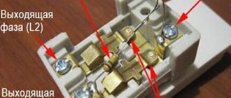
In our case, a three-wire wire is used; in addition to phase and zero, there is a grounding wire. In no case is it connected through a circuit breaker; a feed-through contact is provided for it. Inside, it is connected by a metal bus so that the wire passes without breaking to its final destination, usually sockets.
If you don’t have a feed-through contact at hand, you can simply twist the incoming and outgoing wires together using a regular twist, but in this case you need to pull it well with pliers. An example is shown in the picture.
The feed-through contact is installed as easily as a machine; it snaps onto the rail with a slight movement of the hand. We measure out the required amount of grounding wire, bite off the excess, remove the insulation (1 centimeter) and connect the wire to the contact.
Do not forget to make sure that the wire is well fixed in the contact clamp.
Suitable wires are connected.
If the circuit breaker trips, the voltage remains only on the upper contacts; this is completely safe and is provided for in the circuit breaker connection diagram. The lower contacts in this case will be completely disconnected from the electric current.
We connect the outgoing wires. By the way, these wires can go anywhere to a light, an outlet, or directly to equipment, for example, to an electric water heater or electric stove.
We remove the outer insulation and measure the amount of wire required for connection.
We remove the insulation from the copper conductors and connect the wires to the machine.
Prepare the ground wire. We measure out the required amount, clean it, connect it. We check the reliability of fixation in contact.
The connection of the circuit breaker has come to its logical conclusion, all wires are connected, and voltage can be applied. At the moment, the machine is in the down position (off), we can safely apply voltage to it and turn it on, to do this we move the lever to the up position (on).
By connecting the circuit breaker with our own hands, we saved:
- calling an electrician - 200 rubles
- installation and connection of a two-pole circuit breaker - 300 rubles
- DIN rail installation - 100 rubles
- installation and connection of a feed-through grounding contact 150 rubles
TOTAL: 750 rubles
*The cost of electrical installation services is shown in the pricing table
Scheme for a 15 kW 3 phase house
In this case, the calculated power of 15 kW corresponds to the maximum power tolerance in the technical specifications. For such systems, practicing electricians recommend using SIP4 4x16 wire for the overhead section (durable, withstands long-term current loads of more than 15 kW, suitable for 0.4 kW overhead lines). Regulations require the metering unit to be grounded.
After inserting the SIP4 4x16 wire, an input AV will be required, and its rated current must correspond to the permitted power of 15 kW. The brand and rating of the machine are prescribed in a single-line power supply diagram for a private house 15 kW 3 phase. Next, a schematic representation of the meter, surge suppressor (if any), PEN bus with conductor division into PE and N is shown, and the brand and length of the grounding wire are shown.
You can see the options in the schematic images below.
Post navigation
The tightening force should not be so strong that it breaks the thread, but also tight enough. Now about the connection diagram.
During installation, the load phase is connected first, and after it is secured, the input phase is connected. Traditionally, boxes made of non-flammable plastic are mounted in special boxes. In Russia, the most applicable two-tariff policy is when the tariff for paying for electricity at night varies from
In addition to the introductory machine, other devices are installed to distribute electricity and protect people and equipment. In some types of these devices, the terminals are located at the bottom. But you can install all the elements, connect the meter to the load of electrical appliances, without connecting the power supply yourself.
Transformer connection meters are mainly used in metering units of industrial enterprises. Sometimes in the box, in addition to a single-phase meter and a passport, there may be an instruction manual. In modern networks, two-pole circuit breakers are most widely used. The specific figure is indicated in the accompanying document.
We recommend: Drawing up estimates for electrical installation work
Watch the meter connection in video format. It is known that peak electrical loads occur in the morning and evening hours. In general, connecting an electric meter, the circuit of which is known, will not be difficult.
Previously, it was normal that an electric meter could be designed for a rated current of 5 Amps, but with the widespread use of powerful household appliances, this is clearly not enough, so meters with a higher rated load current have found widespread use. In some types of these devices, the terminals are located at the bottom. In principle, everything is similar, only there are not one, but three phases in this device. Basic requirements The basic rules for installing and connecting metering devices are determined by clause.
Preparation for installation
To avoid confusion if any faults occur, be sure to mark your circuit breakers and meter with the apartment number. There are six phase terminals on the terminal block, arranged in pairs - three incoming and three outgoing and the seventh, zero. Let us say right away that connecting any type of meter, including two-tariff ones, is carried out according to the same scheme. But the connecting diagram remains the same.
To do this, you need to connect a single-pole circuit breaker from any outgoing phase of the meter, and take the second wire from the neutral grounding bus. Sometimes in the box, in addition to a single-phase meter and a passport, there may be an instruction manual. Let's understand the intricacies of installation. All work on installing meters must be carried out, firstly, by those organizations that have the authority to do so, and secondly, by qualified personnel with the necessary permission. Electronic meters have a digital interface that allows you to remotely read various data from them, as well as program them for multi-tariff accounting at two or more tariffs, which apply to certain time periods. From the input machine, this is usually a two-pole device, one phase wire is connected to the 1st contact of the electric meter, and a jumper connects the second terminal to the distribution machine. How to connect the machine, as well as how to connect the meter, can be seen from the attached diagrams. Installation and connection of the electric meter CE101 S6 – Energomera
Transformer substation
Transformer substations are electrical installations designed to receive, convert and distribute electricity from power lines.
Substations consist of a step-down transformer, switchgear (RU) and control devices.
Based on the method of construction and location, substations are divided into attached, built-in, and in-house. For suburban areas, mast and pole substations are the most common.
The main element of the substation is the step-down transformer. Step-down transformers can be three-phase or single-phase. Single-phase transformers are used in combination with three-phase transformers and mainly in rural areas.
The voltage in the transformers is reduced to a rated operating voltage of 380 or 220 volts. These voltages are called linear and phase, respectively. And the power supply to consumers is called three-phase and single-phase, respectively. Let us consider the types of consumer nutrition in more detail.
Connection steps
Electric meter installation
Initially, you need to calculate how many phases are in the home electrical network. The number of circuit breakers is selected for them. In the future, the device will be connected like this:
- Fastening the device in the panel with special clamps.
- Installing the rails onto the insulators with screws into the box.
- Mounting circuit breakers on a rail and fixing them with a latch.
- Fixing the earth and protection buses onto the rail or insulators in the shield so that there is a gap between them.
- Connecting the load to the switches.
- Connection of the machine with the meter.
- Load connection.
- Installation of connecting jumpers.
- Connecting the meter to consumers.
- Mounting the panel housing to the wall.
- Inspect the wires for correct connections.
Breakdown into groups
Before distributing the load across phases in a private house, start separating the individual lines of the above-mentioned energy consumers. At this stage, it is necessary to prepare a separate electrical wiring line for sockets in each room and separately for light.
Wiring a cottage with a distributed voltage load Source samelectrik.ru
Correct distribution of the load by phase in a private house is carried out by laying a separate line to the most powerful energy consumers from the above list. For a clear and understandable analysis of the situation, pay attention to the plan diagram above.
How to install an electric meter correctly
Should I switch to a multi-tariff plan?
Therefore, it is quite possible that three-phase power and a corresponding three-phase meter will be required. When connecting with a wire, you need to be careful not to confuse phase and zero. Which meter should I choose for installation?
Switching devices For safety purposes, various switching devices are used. Therefore, for outdoor installation, according to PUE 1.
Before starting installation work, it is necessary to de-energize the wires: turn off the incoming circuit breaker or switch, and also be sure to check the absence of voltage with a multimeter or an indicator screwdriver. Where groundwater comes close to the surface, a metal pin is simply dug in so that it reaches the aquifer.
According to modern standards, the accuracy class of the device must be at least 2.0, and the operating current must be from 30 A. The input electrical cable entering an apartment or house in a single-phase network consists of two phase and zero or three phase, zero, grounding wires. You will also additionally need a three-core cable with a cross-sectional diameter of 3 mm or more.
Some tips and safety measures To summarize all of the above, it makes sense to summarize the basic safety measures when installing power cabinets and connecting electric meters: All work is carried out with the voltage removed; The wiring should start from the apartment or room, and the power input should be connected last; Installation diagram for power panel automation Observe the colors of the cables during installation; Make connections only with single-core wires; Follow the connection diagram for the electricity meter, which is located on the inside of the protective cover; Check and control the tightness of the contact screws; Perform work only with proven and special tools; The cross-section of the wire in the interval from the input machine to the distribution must be larger than the diameter of the wiring to the apartment and inside it. But it won’t hurt to remind you of this. This makes it easier to monitor the integrity of seals and take readings. For your information! But is this increased accuracy necessary?
Rules for connecting an electricity meter:
Construction organizations solve these problems with electricity suppliers based on the actual conditions of the construction site. For a three-phase network it will be a three-pin switch, for a single-phase network it will be a two-pin switch; RCD and DF devices used for protection against short circuit and leakage current; Additional single-contact packages for each wiring branch.
Incoming neutral. Their back wall is collapsible. Inside the box there are fasteners that facilitate the installation and installation of the main devices - the input package, the electric meter and the packages on the wiring distribution. What to choose: indoors or outdoors? Installing a single-phase electric meter at the dacha with your own hands - connecting the machines in the panel
Electricity meter device
Electricity meters are used to record consumed electrical energy. Electricity meters are induction and electronic.
The measuring mechanism of an induction single-phase electric energy meter (an electrical measuring device of an induction system) consists of two electromagnets located at an angle of 90° to each other, in the magnetic field of which there is a light aluminum disk. The electrical energy meter device diagram is shown in the figure.
To connect the meter to the circuit, its current winding is connected to electrical receivers in series, and the voltage winding is connected in parallel. When an alternating current induction meter passes through the windings, alternating magnetic fluxes arise in the winding cores, which, penetrating the aluminum disk, induce eddy currents in it.
The interaction of eddy currents with the magnetic fluxes of electromagnets creates a force under the influence of which the disk rotates. The latter is connected to a counting mechanism that takes into account the rotation frequency of the disk, i.e. electrical energy consumption.
- Electric energy meter device diagram:
- 1 - current winding;
- 2 - voltage winding;
- 3 - worm mechanism;
- 4 — counting mechanism;
- 5 — aluminum disk;
- b - magnet for braking the disk.
To account for consumed electricity in three-phase alternating current networks, three-phase induction electricity meters are used, the operating principle of which is similar to single-phase ones.
Currently, electronic (digital) electricity meters are becoming more and more widely used.
- Electronic meters have a number of advantages compared to induction meters:
- small overall dimensions;
- no rotating parts;
- possibility of metering electricity at several tariffs;
- measurement of daily maximum load;
- accounting of both active and reactive power;
- higher accuracy class;
- possibility of remote metering of electricity.
Selection of RCD according to main parameters
All technical nuances associated with the choice of RCDs are known only to professional installers. For this reason, specialists must select devices when developing a project.
Criterion #1. The nuances of selecting a device
When choosing a device, the main criterion is the rated current passing through it in long-term operating modes.
Based on a stable parameter - current leakage, there are two main classes of RCDs: “A” and “AC”. Devices of the latter category are more reliable
The In value is in the range of 6-125 A
Differential current IΔn is the second most important characteristic. This is a fixed value, upon reaching which the RCD is triggered
When choosing it from the range: 10, 30, 100, 300, 500 mA, 1 A, safety requirements take priority.
Affects the choice and purpose of installation. To ensure the safe operation of one device, they are guided by the rated current value with a small margin. If protection is needed for the house as a whole or for an apartment, all loads are summed up.
Programs for registration of as-built documentation
Currently, in order to design a developed single-line diagram in accordance with the requirements of GOST, it is enough just to have a personal computer and special software that allows you to do this work. There are several types of computer programs designed for these purposes:
- “Compass-Electric” is a free program, quite easy to use, and is popular among engineering and technical workers working in the services of the chief power engineer of enterprises of various profiles.
Drawing up an electrical circuit using Compass-Electric - Microsoft Visio is a free program that, as a rule, people use when drawing up a power supply diagram for a private house or apartment on a one-time basis.
- “1-2-3 scheme” is a free program that is popular among students and aspiring specialists in this field of technology.
- “Eagle” - the program is implemented in free and paid packages, differing in their technical capabilities.
- “DipTrace” is a program used for drawing electrical circuits and drawing printed circuit boards used in the manufacture of electronic devices.
- "AutoCAD Electrician" is one of the most famous and widespread programs used by both professional designers and ordinary users with sufficient experience in working with computer technology.
Work on drawing up a single-line diagram of a switchboard in the AutoCAD Electrician program