Creating a modern indoor electrical network is a responsible undertaking associated with calculations, selection of wires and electrical installations, and installation work. At the same time, one of the main tasks remains to ensure the safety of residents and the safety of property. Do you agree?
If the protective devices are correctly selected and the connection diagram of the RCD and circuit breakers is thought out, all risks are reduced to a minimum. But how to do that? What to consider when choosing? We will answer these and many other questions in our material.
You will also be able to understand the principle of operation of an RCD and its connection options. Expert advice and installation nuances are collected in this material. In addition, the article contains videos from which you will learn about the main mistakes when connecting and see how an RCD is connected in practice.
Purpose and principle of operation
Three-phase residual current device (RCD)
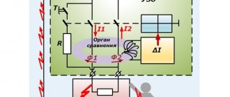
A 3-phase RCD is designed to equalize the current that passes through the phase and neutral wires. In the absence of emergency situations, the indicated values are equal. Stable operation of electrical devices is possible because counter currents in the windings compensate each other. In the event of emergency situations, the protection device turns off the power to electrical appliances. This is observed when the insulation of wires is broken, which provokes the leakage of charged particles. As a result, the currents passing through the neutral and phase wires will have different values.
In every home, a situation can occur when an electric current penetrates the body of a washing machine or water heater. When the potential begins to flow to the floor, the 3-phase RCD will react and turn off the power to the devices. Therefore, when using this circuit breaker, you can be confident in your safety.
Connecting an RCD is relevant for powerful electrical appliances in the kitchen and bathroom. Condensation collects on their metal body, which together forms a potential conductor of electricity.
It’s good when protective shutdown is present on sockets, lamps and low-power household appliances. In the event of emergency situations, these consumers pose no less danger to humans.
Schemes for 3-phase network
In homes, industrial premises and other structures, there may be a different option for arranging power supply.
Thus, for apartments, connecting a 3-phase network is uncharacteristic, but for equipping a private house this option is not uncommon. Here other circuits for connecting the protection device will be used.
Option #1 – general RCD for a 3-phase network + group RCDs.
For a 380 V network, a 2-pole device is not enough; a 4-pole analogue is needed: you need to connect 1 neutral wire and 3 phase wires.
The type of wires is important. For a 1-phase network, a standard VVG cable is suitable, while for a 3-phase network it is recommended to install the more fire-resistant VVGng cable. We wrote about choosing the appropriate type of wire in our other article.
Device diagram
First of all, let us present a schematic diagram of the device, indicating its main elements.
RCD diagram
Designation:
- A – Relay that controls the contact group.
- B – Differential CT (current transformer).
- C – Phase winding on the DTT.
- D – Zero winding on the DTT.
- E – Contact group.
- F – Load resistance.
- G – Button that starts testing the device.
- 1 – Phase input.
- 2 – Phase output.
- N – Neutral wire contacts.
Marking
The marking is applied to the front panel of the device; we will tell you what it means using the example of a two-pole device.
RCD marking
Designations:
- A – Abbreviation or manufacturer’s logo.
- B – series designation.
- C – The value of the rated voltage.
- D – Rated current parameter.
- E – The value of the shutdown current.
- F – Graphic designation of the type of disconnecting current, can be duplicated with letters (in our case, a sinusoid is shown, which indicates the type of AC).
- G – Graphic designation of the device on circuit diagrams.
- N – Value of conditional short-circuit current.
- I – Device diagram.
- J – Minimum operating temperature (in our case: – 25°C).
We have provided standard markings that are used in most devices of this class.
Principle of operation
To understand how the protective structure performs its safety functions, you need to understand the operating principle of the RCD and the connection diagram. It has been established that the current from the network passes through the phase conductor through the load and then returns through the neutral wire. The operation of the device is based on this pattern.
Important! The operating principle of the RCD is based on comparing the values of the electric current at the output and input of the object, which is protected.
If Iin = Iout, then the device does not respond. As soon as Iin > Iout, the protective structure senses the leak and reacts as a result.
In other words, the currents passing through the phase and neutral wires must be the same (for a single-phase network). When the network is three-phase, then the value in the neutral is equal to the sum of the electric currents flowing in the phases. The inequality of electric currents indicates a leak, to which the device reacts.
When does an RCD not help?
However, you should not consider the RCD a panacea for any problems with electricity. The device is not smart enough to understand what exactly is included in the electrical circuit - a light bulb or a person. Shutdown will only occur if there is a leak.
The RCD does not protect against overvoltage, incl. from pulsed, as well as from low voltage, which “kills” electric motors - in a refrigerator, washing machine, and so on.
The unit also does not protect against short circuits. This task is performed by a circuit breaker or differential circuit breaker.
How many RCDs need to be installed?
To determine the exact number of RCDs required for a particular room, you will need a specialist who can carry out the appropriate calculations. For example, in a 1-room apartment, most likely, one such device, designed for a leakage current of 30 mA, will be enough. But in an apartment with four rooms and 15 groups of sockets, you will need at least five RCDs, as well as one device for the entire lighting group, electric stove and water heater.
It is usually assumed that one group of electrical appliances consists of one 30 mA residual current device plus one 100 or 300 mA fire protection RCD.
NOTE! To control the electrical wiring as a whole, it is recommended to install one general RCD with a rated breaking current of 300 mA at the entrance to a private house in addition to the calculated ones.
When is it not practical to install an RCD?
Sometimes there is simply no point in installing a device. One such situation is the presence of old and decrepit wiring. The ability of an RCD to detect a leak can become a headache if the device begins to operate unpredictably (which is what happens with poor wiring). In this case, the best solution would be to install the RCD not in the power supply circuit of the apartment as a whole, but in places with increased danger for using sockets.
There is also no point in buying a low-quality RCD. On the modern market you can find not only original devices, but also a wide range of fakes of unknown origin. Many of these devices are made “on the knee around the corner.” The use of such devices is completely unacceptable and inappropriate. Before purchasing, carefully study the technical documentation and quality certificates of the purchased unit.
It makes no sense to install the device in lines that supply voltage to stationary equipment and lamps, as well as in general electrical networks.
Connecting heaters according to the STAR scheme for an electric boiler
In electric heating boilers, heating elements can be connected in various ways, but to demonstrate the STAR-type connection diagram, we will describe the option of installing dry heating elements to a 3-phase power supply network with a voltage of 220V.
The high power of dry water heating elements imposes certain requirements on the quality of connections. The reliability of the connections must be ensured by high quality heat-resistant wires and strict compliance of all actions with the diagram described in the instructions.
The first thing to do is to screw on the M4 nut when connecting the phase drives. Next, you need to apply the washer and install the ring terminal of the power wire. The next step is to apply another similar washer, on top of which another special Grover spring washer is placed. And all this needs to be securely fixed with an M4 nut.
The wires that lead to the neutral phase are secured using an M8 bolt. The neutral wire must be placed in a jumper, which is located between the contacts of the heating element holes.
Be sure to ground the body of the heating element and power wires after connecting all the wires to the supply and neutral contacts of the heating element. In most cases, in standard electric boilers, the grounding bolt is located on the left side near the block with heating elements. We must connect the grounding wire to it.
After connecting the wires, ground the heater body and the heating element connection wires. Typically, grounding boilers have a bolt on the left side of the electric heater block, to which the grounding conductor should be connected.
You can use either a separate potential equation wire or a wire from the grounding terminal block of the control unit for grounding.
You can clearly see all of the above described in the figure below in the form of a diagram and photo of connecting the heating element.
If you have done everything in strict accordance with the instructions, the connection of the heating element of the electric boiler can be considered complete. All that remains is to return the protective casing to the heating unit.
In electric boilers, heating is controlled based on data from temperature sensors. Thermostatic devices are located on the main control panel of the boiler. The thermostat will receive data on the temperature of the heating element and the temperature of the coolant. Based on these readings and the settings set on the thermostat, a decision is made automatically to supply or turn off power to the heating elements. While the temperature is below the set one, power will be supplied and the heating elements will produce heating, and when the threshold value is reached or exceeded, the power will be turned off and the heating elements will stop heating. When it cools down to the lower threshold, the heating element will turn on again.
The thermostat allows a person to set the temperature (upper and lower thresholds) just once, and then the electric boiler will operate automatically, and the temperature will be maintained at the desired level.
There is an option to use thermostats with several types of temperature sensors, which will not only control the heating of the heating element itself, but also the air temperature in the room. To do this, the temperature sensor must be installed at a distance from the boiler and coolant.
List of main characteristics
Having understood the design of the devices and their operating principles, let’s move on to the main parameters. These include:
- The type of electrical wiring being protected, it can be single-phase or three-phase. This parameter affects the number of poles (2 or 4).
- The rated voltage is 220-240 Volts for two-pole devices, 380-400 Volts for four-pole devices.
- The value of the rated current load, this parameter corresponds to that of circuit breakers (hereinafter referred to as AB), but has a slightly different purpose (will be discussed in detail below), measured in Amperes.
- Rated value of differential (breaking) current, typical values: 10, 30, 100 and 300 mA.
- Type of disconnecting current, accepted designations:
- AC – Corresponds to sinusoidal alternating current. Both its slow increase and sudden manifestation are allowed.
- A – To the previous characteristics (AC), the ability to monitor the leakage of rectified pulsating current is added.
- S – Designation of selective devices; they are characterized by a relatively high response delay.
- G – Corresponds to the previous type (S), but with less delay.
Now it is necessary to explain the meaning of the rated current parameter, since it raises some questions. This value indicates the maximum permissible current for this electromechanical protective device.
When selecting this parameter, it is necessary to take into account that it should be one step higher than that of AB on a given line. For example, if the AV is designed for 25 A, then it is necessary to install protective devices with a rated current of 32 A.
Please note that this type of device is not intended to be triggered by short circuits and overloads. If such an accident occurs, all the wiring will burn out and a fire will break out, but the device will remain turned on. That is why such protective devices must be used in conjunction with AV. As an option, you can install a differential circuit breaker, which is essentially also a residual current device, but equipped with a short-circuit and overload protection mechanism.
How to choose a circuit breaker and wire for an electric boiler
admin Date: 02/04/2019
To protect electric boilers from overload, circuit breakers are used. How to correctly calculate the parameters and choose a circuit breaker for an electric boiler.
The circuit breaker for the electric boiler protects the power cable from thermal overload. The cause of insulation melting is prolonged overheating of the wires caused by excess current. This may cause a short circuit.
As a rule, the fuse is installed on the meter, on the wire leading to the protected equipment.
To correctly select a pass-through switch with an automatic circuit breaker, you need to select the wire cross-section, calculate the rated current of the electric boiler and take into account the nature of use of the connected equipment.
The wire
To connect an electric boiler, you need to lay a dedicated cable. Even if the boiler has a power of up to 3 kW at 220 V, you should not plug it into the network through a regular outlet - you will load the internal wires of the electrical wiring unnecessarily.
Species and types
Modern manufacturers offer a variety of types and types of RCDs. The two most popular types of units in terms of their internal design on the electrical goods market are electromechanical (do not depend on current) and electronic (depend on). Selective and fire-fighting devices are also distinguished.
Electromechanical
Electromechanical RCDs are widely used and are used in AC electrical circuits. What causes this? The fact is that when a leak is detected, such a device will work, preventing dire consequences even at the smallest voltage.
This type of RCD in many countries is considered a standard of quality and one that is mandatory for widespread use. No wonder, because such an RCD will be operational even if there is no zero in the network and can save someone’s life.
Electronic
Such RCDs are easy to find on any construction market. The difference between them and electromechanical ones is that they are located inside the board with an amplifier, which requires power to operate.
However, such RCDs, as already mentioned, have a huge drawback - it is not a fact that they will operate in the event of a current leak (it all depends on the voltage in the network). If the zero burns out, but the phase remains, then the risk of electric shock does not go away.
NOTE! We are talking about the advantages and disadvantages of RCDs in general, and not specific models. If you are very lucky, you can become the owner of a low-quality RCD, both electromechanical and electronic.
Selective
The main difference between selective RCDs and their “brothers” is the presence in the circuit of a time delay function for turning off the circuit that powers the load, i.e. selectivity. Often this parameter does not exceed 40 ms. From this we conclude that selective devices are not suitable for protection against injury from direct contact.
Another feature of selective units is their good stability in response to current and voltage surges (the probability of false alarms is almost zero).
Fire protection
As the name suggests, such RCDs are used in the power supply systems of apartments and houses to prevent fires. However, they are not able to protect a person since the leakage current for which they are designed is 100 or 300 mA.
Typically, these units are installed in metering panels or in floor distribution boards. Their main task:
- input cable protection;
- protection of consumer lines in which differential protection is not installed;
- as an additional level of protection (if the device below it suddenly does not work).
Is grounding necessary for an RCD?
Many homeowners believe that grounding for a protective device is mandatory, that it will only work normally if there is an electrical circuit that has a phase, a neutral and a ground (PE, yellow-green). Often homeowners ask another question: which is better - grounding or RCD. To answer it, you just need to compare the purpose of each protection.
The main function of a residual current device is to de-energize the network when a leakage current appears on the housing of a household appliance. This reaction helps prevent electric shock to a person. Grounding serves the same purpose, but its operation is different. If current appears on non-conductive parts, a short circuit occurs due to grounding. As a result, the machine’s protection is triggered and the equipment is de-energized.
Is RCD grounding necessary? It is desirable. Both methods can be used either separately or together, in combination. However, there is no need for grounding to use an RCD. The protection device is capable of operating in a single-phase two-wire network without a ground wire. The correctness of this conclusion can be verified by studying the RCD model. The device has 2 terminals - for phase and neutral, but there is no grounding contact.
For this reason, the device can be used in houses commissioned back in Soviet times. They did not have a grounding conductor, because the range of household appliances in stores was minimal. Such old apartments need an RCD. The difference between networks with and without grounding is only in the response speed. In the first case, the device responds almost instantly. In the second - only at the moment when the body of the device touches under voltage. Despite this drawback, serious electric shock can be avoided.
How does an RCD with grounding work?
The choice of protective device depends on the specific network configuration for which it is intended. The first thing you should always pay attention to is the presence or absence of a grounding conductor (PE). In modern houses it is provided for by the design. In old buildings, a PEN scheme is used, where the ground wire is combined with the neutral.
If there is a grounding in the circuit, then before installing the RCD it is necessary to accurately determine its type. In the TN circuit, solid grounding of the neutral conductor is used. TN-C differs in that one wire is intended for the neutral working and protective conductors. In this case, if the PEN conductor breaks, the entire potential may transfer to the body of the device, which has its own grounding.
Sometimes electricians resort to another incorrect scheme: they use a jumper that shorts the ground terminal of the socket and the neutral. In this case, an extremely dangerous situation can arise. If the PEN conductor breaks, the RCD will not work. The consequence will be electric shock to the person. However, there is an option that will allow you to avoid such a development of events. This is touching any ground loop: for example, elements of a water supply or heating system.
The safest scheme for connecting an RCD remains the TN-S scheme, where the protective wire is connected separately and combined with the neutral only in the power source. In this case, the probability of electric shock is reduced to zero even if the grounding or neutral conductor breaks. If both conductive elements are damaged, there is also no danger: the electricity will be completely turned off.
The TN-CS scheme is the last of the options; it is called intermediate. In it, the neutral and ground wires are combined only in separate sections. For such a circuit, the RCD becomes a mandatory part of the circuit. Otherwise, she will be left without protection.
Is an RCD effective without grounding?
After considering the question of how an RCD with grounding works, we need to focus on a diagram without it, since it is not provided for in old houses. In the event of a breakdown on the housing of a household appliance, the device will not immediately operate, since there is no main condition - leakage current due to the lack of grounding.
When a person touches the device, differential current will pass through the body. After some time, the triggering threshold will be reached, after which the current supply to the parting will stop. The severity of the damage depends on the installation of the protective device. Yes, turning off the power in this case will be quite fast. However, the risk of serious electrical injury cannot be ruled out. Therefore, without grounding it is impossible to guarantee the absolute safety of residents.
To protect people in houses with two-wire electrical networks, other devices must be included in the circuit. These are circuit breakers that will de-energize the network during short circuits or overloads. The best solution is difavtomats, which combine the functionality of an RCD and a simple machine. These devices will protect people from electric shock and protect wiring in the event of a short circuit.
Preparing to connect
Properly performed preparatory and installation work will ensure stable operation of the RCD.
Connection diagrams for a three-phase network
When installing RCDs, the following operating diagrams are used:
- Complete shutdown of the electrical circuit. One unit has the ability to de-energize all electricity consumers in the event of an emergency.
- Partial shutdown of devices. When emergency situations occur, only some consumers are de-energized.
The first connection scheme is used in apartment buildings. The device is installed near the electricity meter. If the RCD trips, the whole house is de-energized.
When using the second scheme, the protective mechanism is installed on a section of electrical wiring going to a specific room. Since all devices are connected in series to the circuit, when the RCD is triggered, only the “problem” consumer will turn off, while the others will continue to function.
The second version of the scheme can be implemented in a different way. The point of installation of the RCD becomes the beginning of the serial connection to the wiring, which allows for selective operation of the unit on certain groups of consumers. Also, a protective mechanism can be installed directly in front of the output device.
The need for grounding
Old electrical networks belong to the tn-c system, where there is no neutral conductor to enable grounding. In this case, protection must be provided separately for the home or equipment, which ensures safe drainage of currents. If there is no grounding, installing a 4-pole RCD is prohibited.
The correct connection diagram to the electrical network requires compliance with the following rules:
- The grounding conductor is connected only to the output cable. Connecting directly to an RCD is not permitted.
- If you have a single-phase network, you cannot use a four-pole device.
- Connection to a B3 type network is prohibited.
Connecting an RCD in a two-phase network
Two-phase power refers to non-standard connections, where a converted old-style 127 V transformer was reconnected into a triangle for modern 220 V consumers, which are powered by linear voltage from it.
Rice. 4: Connecting an RCD in a two-phase system
To connect a residual current device to a two-phase circuit, it is necessary to disconnect both wires at the input to the panel, since each of them is under potential. Then each of the phases is connected to the corresponding phase terminals and neutral terminals, further observing their polarity. Unlike a single-phase system, circuit breakers at the output of the RCD must be installed for each line, or they can be replaced with one two-pole one.
Video description
Incorrect connection diagrams for RCDs and automatic machines, as well as real examples when the RCD did not work correctly, are described in this video: The
second problem, after the correct selection of device parameters, is errors during installation, which leads to the uselessness of the protection system. An example is the banal mix-up of tires.
Attention! It is strictly forbidden to mix up the poles “N” and “L”. The device body usually has these designations, and the wiring should vary in color.
If after installation the device shows constant operation or, on the contrary, does not want to respond, then most likely:
- a phase connection to ground occurred after exiting the protection device;
- the installation was carried out poorly, for example, one of the wires is in poor contact with the terminal;
- there was a connection between the neutral wire and the ground in one of the sockets;
- When connecting a circuit of several RCDs, confusion occurred.
In practice, it is not realistic to foresee and describe all possible errors, because they depend largely on the switching scheme used. And the more complex it is (the more devices are included), the more important it is to be attentive.
Connecting an RCD in a three-phase network
Protection of devices powered by three phases at once is carried out according to a similar principle, with the difference that the RCD is selected for four outputs. An example of connection is shown in the figure below:
Rice. 5: Connecting an RCD in a three-phase system
As you can see, in this case, the protective device is also connected after the electric meter and the introductory packet. Individual circuit breakers that respond to phase short circuits are already connected behind it, and, if necessary, more sensitive RCDs are connected to create selective operation for certain groups of consumers.
Since installing a separate device for each phase is too expensive, group RCDs are used in three-phase circuits, which work with all elements of the line at once.
Fire protection RCD for a private home: how to choose and install correctly
A fragment of the connection diagram for a four-pole fire protection RCD at the entrance to a private house explains the main principle of its selection based on differential current.
It is placed at the entrance to the building for protection:
- input cable;
- lines to consumers where individual residual current devices are not used;
- acting as a reserve in case of failure of the main module.
The fire protection RCD is connected to the power supply circuit of the house with mandatory observance of the selectivity of its operation. This is achieved in a comprehensive manner by two settings:
- threefold reserve of the differential current setting in comparison with any group or individual module located below;
- delay in response time by at least 3 times.
A fragment of the above connection diagram shows that the differential current of the fire protection module IΔns is three times higher than the leakage setting IΔn1 or IΔn2 for any group of consumers.
Fire protection RCDs are designed to be triggered by leakage currents of 100, 300 or 500 mA, and human protection modules from differential current are manufactured with settings of 30, 10 or 6 milliamps.
The ability to set a time setting for selective operation is indicated on the module body with the Latin letter “S”.
The correct choice of settings for fire protection, group and individual RCDs for differential current and shutdown time of an emergency is an obligatory principle of reliable liquidation by protecting the damaged area while leaving serviceable equipment energized.
Connecting a three-phase RCD: 4-pole circuit without using a neutral
The case of using a symmetrical load, in which all currents in the phases are always equal, allows one to abandon the operation of the neutral wire and simplify the design.
An example of such a connection is the protection of a three-phase asynchronous electric motor. Its stator windings can be assembled in a star or delta configuration, which provide equal resistance between phases.
The working zero potential is connected to the input contact of a four-pole RCD, and nothing is connected to the output. The potential output terminal N remains empty.
This technique allows you to save money by connecting the motor to the power circuits with a cable with four rather than five cores: three for phase potentials and one for the protective PE conductor.
It is mounted on a special housing grounding bolt.
Connecting a three-phase RCD: 4-pole circuit using neutral
A simplified diagram for connecting a four-pole RCD to a three-phase network can be represented as follows: at the output of the working zero, a busbar is used to distribute neutral potentials N to connected consumers (circuit with neutral).
Consumers can be powered from all 3 phases or just one. The same circuit allows you to simultaneously protect three different single-phase circuits, provided that a common neutral is used.
At the same time, they try to arrange the operation of the equipment in compliance with the uniform distribution of load currents across all phases.
Connecting a three-phase RCD: diagram for a single-phase network
The proposed option is not typical.
It is used as an exception in three cases:
- The owner has an extra protection module that needs to be put into operation. Otherwise, it will simply gather dust without use.
- The assembled single-phase wiring is planned to be converted to three phases in the near future.
- Temporary replacement of a module that fails when an accident occurs.
In all three cases, it is necessary to pass the phase potential through those terminals to which the “Test” button winding is connected. Otherwise, it will not work during manual checks.
.
Protection options for single-phase network
Manufacturers of powerful household appliances mention the need to install a set of protective devices. Often, the accompanying documentation for a washing machine, electric stove, dishwasher or boiler indicates which devices need to be additionally installed into the network.
Considering the number of different circuits serving sockets, switches, equipment that load the network to the maximum, we can say that there are an infinite number of RCD connection schemes. At home, you can even install a socket with a built-in RCD.
Next, we will consider the popular connection options, which are the main ones.
Option #1 – general RCD for a 1-phase network.
The location of the RCD is at the entrance of the power line to the apartment (house). It is installed between a common 2-pole circuit breaker and a set of circuit breakers for servicing various power lines - lighting and socket circuits, separate branches for household appliances, etc.
Suppose that a current leak occurs due to contact of a phase wire with a metal device connected to the network. The RCD trips, the voltage in the system disappears, and it will be quite difficult to find the reason for the shutdown.
The positive side concerns savings: one device costs less, and it takes up less space in the electrical panel.
Option #2 – general RCD for 1-phase network + meter.
A distinctive feature of the scheme is the presence of an electricity meter, the installation of which is mandatory.
Current leakage protection is also connected to the machines, but a meter is connected to it on the incoming line.
The advantages of this arrangement are the same as the previous solution - saving space on the electrical panel and saving money. The disadvantage is the difficulty of detecting the location of a current leak.
Option #3 – general RCD for a 1-phase network + group RCDs.
The scheme is one of the more complicated variations of the previous version.
Thanks to the installation of additional devices on each operating circuit, protection against leakage currents becomes double. From a security point of view, this is an excellent option.
To prevent both devices (private and common) from triggering at once, it is necessary to observe selectivity, that is, when installing, take into account both the response time and the current characteristics of the devices.
The positive side of the scheme is that in an emergency one circuit will turn off. It is extremely rare for cases where the entire network goes down.
This can happen if the RCD installed on a specific line:
- defective;
- out of order;
- does not match the load.
To prevent such situations from arising, we recommend that you familiarize yourself with the methods of testing RCDs for functionality.
Disadvantages - the electrical panel is overloaded with many similar devices and additional expenses.
Option #4 – 1-phase network + group RCDs.
Practice has shown that the circuit without installing a common RCD also works well.
Of course, there is no insurance against failure of one protection, but this can be easily fixed by purchasing a more expensive device from a manufacturer you can trust.
From the point of view of economy, wiring several devices loses - one common one would cost much less.
If the electrical network in your apartment is not grounded, we recommend that you familiarize yourself with the diagrams for connecting an RCD without grounding.
Checking the RCD
After switching all circuits, the intra-house network must be powered. If the circuit breakers or RCDs do not turn off, then there is no short circuit and the neutral conductor is not in contact with ground.
Next, press the “TEST” or “T” button located on the front panel of the device. In this way we forcefully simulate the occurrence of leakage current. A working RCD should immediately operate and de-energize the protected area. If this does not happen, then in the event of an emergency the device will not help cope with the problem.
The last stage of the test can be considered the supply of load to the RCD. It is necessary to turn on one by one all devices that will work in a specific circuit and the network as a whole. In case of possible problems, it is necessary to make changes to the protection circuit or change the ratings of residual current devices.
RCDs are not the only way to protect people from electric shock and network overloads, which can lead to fire. But often it is these devices that save lives and ensure the safety of citizens’ property.
RCD installation instructions
First you need to choose a place to mount the device. There are 2 options: panel or cabinet. The first resembles a metal box without a lid, fixed at a height convenient for maintenance.
The cabinet is equipped with a door that can be locked. Some types of cabinets have openings so that you can take meter readings without specially opening the door and turn off the devices.
The neutral wire is always connected to the left terminals at the input and output, and the phase wire to the right terminals. One of the options:
- input terminal N (upper left) – from the input circuit breaker;
- output N (lower left) – to a separate zero bus;
- input terminal L (upper right) – from the input circuit breaker;
- output L (lower right) – to group machines.
By the time the protective device is installed, circuit breakers may already be installed on the panel. To organize the arrangement of devices and wires, you may have to rearrange the devices in a certain order.
We present an example of installing an incoming RCD in an electrical cabinet that already has a meter, an incoming circuit breaker and several circuit breakers for individual circuits - lighting, socket, etc.
Never connect an RCD at the input - it always follows the general input circuit breaker. If a counter is used, the residual current device moves to the third position from the input.
Description of the connection process:
- We install the device on the DIN rail to the right of the machine - just touch it and press with a little force until it clicks;
- we stretch the cut and stripped wires from the machine and the zero bus, insert them into the upper terminals according to the diagram, tighten the fastening screws;
- In the same way, insert the wires into the lower terminals and tighten the screws;
- testing - first turn on the general circuit breaker, then the RCD, press the “Test” button; When pressed, the device should turn off.
To make sure the connection is correct, leakage current is sometimes simulated. Take two working wires - “phase” and “ground”, and simultaneously connect them to the base of the electric lamp. A leak appears and the device should work immediately.
Basic mistakes when connecting an RCD
When connecting an RCD, many people make common mistakes that can have very serious consequences for a person. To avoid them, follow these rules:
- the input terminals of the residual current device must be connected only after the corresponding circuit breaker; direct connection to the network is unacceptable;
- observe the correspondence of neutral and phase contacts, their designation is specifically indicated on the housing;
- when installing wiring, carefully follow the diagram, especially for objects with branching, a large number of connected objects and several RCDs for them;
- if there is no grounding conductor in an apartment or house, then it should never be replaced with a wire thrown over heating radiators or water pipes; grounding must be made in accordance with the rules;
- pay attention to the performance characteristics of the purchased devices (rated operating current and shutdown current) and their compliance with the network parameters, for example, if a current of 50A can flow in the line, then the device should be selected at least 63A.
To protect yourself during connection, follow basic electrical safety rules.
What mistakes should you avoid?
Before connecting, be sure to double-check the technical specifications of the devices. The rated current must be equal to or higher than the same parameter for the input circuit breaker. The values can be easily determined by the markings.
Electricians recommend choosing a protective device one step higher, that is, for a 50A circuit breaker, a 63A RCD is suitable.
You can correctly calculate the parameters, choose a machine and an RCD with the correct rating, but make a small mistake during installation, as a result of which the system will be useless.
For example, beginners often confuse tires. It should be remembered that I use different buses for the neutral conductor and the ground wire. In addition, each device requires a separate bus: for 5 RCDs - 5 buses.
In no case should the poles N and L be confused . They have letter designations on the body, and the wires differ in color, so you need to be careful.
If a false alarm occurs or, on the contrary, the device does not respond, the reason may be the following:
- “phase” and “ground” are connected after the RCD;
- incomplete connection - conductor N is not inserted into the corresponding terminal;
- “zero” and “ground” are connected in the socket;
- confusion between connecting two or more RCDs to electrical installations.
In practice, there are many more errors, since different schemes are used. The more devices are involved in assembling the electrical panel, the more careful you need to be when connecting.
What are called difavtomats?
Differential automatic machines are, in fact, also a type of RCD. It just turns out that these are two devices in one, since the mechanism is capable of controlling both current leakage and voltage.
The differential machine consists of a switch and a machine
On the body of this device you can notice the presence of special markings that not only indicate the rated current, but also the maximum value that it can withstand. However, the mechanism will work at a lower rated current.
It turns out that this is an improved device that replaces the automatic machine and the standard version of the RCD. The difference is that such a mechanism has a higher cost.
Safety regulations
How to properly connect wiring to machines
There are a large number of devices that will make it easier to connect contacts to automation. In order to choose the appropriate option, we will consider them in detail.
Flexible wire lugs
In order to connect elements of an electrical panel, flexible wires with many wires are often used, because even a beginner can cope with connecting such contacts. But there is a nuance here too.
As we have already discussed above, many craftsmen fix the wire with a clamp without termination, which is why the fragile wires begin to break off and the contact weakens.
If stranded wire is used during installation, then do not forget about the lugs
Sometimes it becomes necessary to fix two contacts at once into one clamp, so double tips were invented for this purpose. They are best suited when you have to install a lot of jumpers.
Special tip for forming bridges
Arched bend
Usually, to connect the conductors to the clamps, it is necessary to remove 10 millimeters of the insulating layer - this is enough to form an arc on the messenger, which is then placed in the terminal. As practice shows, most electricians, in the absence of tips, use this method.
As a result, it is possible to obtain reliable contact that will not weaken over time. This method is suitable if there is a monolithic core at the end.
Thanks to this connection, the area of interaction between the contact and the clamp expands, this will avoid problems with the operation of the machine
Unbreakable jumpers
When you have to connect several machines with one wire, it becomes necessary to use a comb (bus). However, it is not always at hand, so you can form a homemade comb from wire of any cross-section.
You should bend the wire so that you get a comb. Then, at the bend site, you need to strip the wires.
Method for forming a continuous comb
Safety Basics
Work is carried out in compliance with the following rules:
- The line is de-energized and checked for absence of voltage with an indicator screwdriver. If the switch is located far from the installation site of the RCD, you should attach a sign on it with the text “People are working!” or place a watchman. To be safe, it is recommended to disconnect the wires from the terminals.
- When connecting wires, use only methods approved by the PUE: clamps, terminals, crimping with sleeves, welding. Soldering is not recommended; twisting is prohibited.
- The correct installation is checked by measuring the resistance of the phase-zero loop. A high indicator indicates poor contact in one of the connections. During operation, such places become hot and can cause a fire.
- Before applying voltage, protect eyes and exposed parts of the body. A low-quality product may fly apart.
- Do not use wires with insulation of the same color.
Sources
- https://StrojDvor.ru/elektrosnabzhenie/princip-raboty-i-sxema-podklyucheniya-uzo-v-trexfaznoj-seti/
- https://electrik-ufa.ru/raznoe/printsip-raboty-uzo-v-odnofaznoj-seti
- https://odinelectric.ru/equipment/circuit-breaker/chto-takoe-uzo-naznachenie-markirivka-vidy
- https://dom-i-remont.info/posts/elektrika/nadezhnaya-elektrozashhita-seti-kak-rabotaet-uzo-s-zazemleniem-ili-bez-nego/
- https://www.asutpp.ru/kak-pravilno-podklyuchit-uzo.html
- https://ElectrikBlog.ru/kak-podklyuchit-uzo-pravilno-instruktsiya-na-7-skhem-s-foto/
- https://zen.yandex.ru/media/rmnt/kak-vybrat-i-pravilno-podkliuchit-uzo-5bd9504cb098ea00a9cc3e8d
- https://altenergiya.ru/poleznye-stati/sxemy-podklyucheniya-uzo-v-odnofaznoj-i-trexfaznoj-seti-varianty-montazha-i-pravila-bezopasnosti.html
- https://stroyhelper.ru/shema-podklyucheniya-uzo/