As is known, the power supply system for the end consumer is built according to the schemes recommended by the Electrical Installation Rules (PUE). A power cable is supplied to the facility, and further wiring occurs in the distribution panel. For ease of installation and organization of power supply lines, inputs with different values are combined into contact groups. A bus with a phase, a zero bus is a contact block in which there is the ability to reliably connect several conductors to power electrical installations.
Requirements for the zero bus
- For a group network, the bus must be a single conductor, without the possibility of switching between its parts.
- The resistance should be the same along the entire length.
- Within one group line, it is allowed to combine conductors PE (protective grounding) and N (working zero).
In this case, after dividing the PEN input into PE and N buses, end consumers are connected to different buses.Important! Using one bus to connect the working zero and grounding is prohibited! This is a fundamental issue, it is necessary to understand the difference between splitting and merging PE and N.
From the moment of separation, the ground and neutral lines can be laid in one power cable, but the conductors must be insulated.
- Regardless of the connection method (three-phase or single-phase), the cross-section of the neutral conductor must correspond to the cross-section of any of the phase conductors. The same requirement applies to the cross-section of the tire itself.
- The cross-section of the connecting wires from the bus to the final electrical installation cannot be higher than the cross-section of the input power wire.
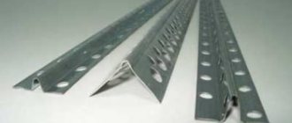
- If the bus is a structure with holes for connecting conductors, the actual cross-section is considered to be the geometric parameters in the thinnest part.
- There are no requirements for the mandatory production of a zero working tire from a specific metal. However, in practice, copper or brass is used. When calculating the cross-section of aluminum busbars in relation to copper busbars, a coefficient of 1.52 is applied.
For convenience, we will consider a single-phase circuit, which is used in most apartments in multi-storey buildings. Two main lines: phase and zero, are always present. They are inserted into the meter (electricity meter), and at the output they become available for further wiring. Depending on the system used, either only a zero bus or a zero and ground bus can be installed.
Copper ground bus
The copper-based grounding bus refers to conductors with low resistance values.
The standard element is fixed to the body of the electrical panel, and also easily withstands thermal loads and high voltage during a short circuit. One of the most popular options is a grounding copper strip, made using high-quality electrical copper of the “M-1” grade.
Copper grounding bar
The protective element is manufactured in accordance with GOST 434-78, and is characterized by a high level of alloy purity with a solid metal content of 99% or more.
Due to the high quality of the source material, the copper busbar is designed for operation in operating temperatures ranging from minus 55°C to plus 280°C, with a maximum operating voltage of 1000 W.
Established standards regulate the marking of copper grounding bars with mandatory indication of thickness, width and length.
Tire installation option
Copper grounding bars can be used not only indoors, but also outdoors, due to the following performance characteristics:
- high level of thermal conductivity;
- high level of electrical conductivity;
- low resistivity values;
- resistance to corrosive changes.
When installed externally, copper grounding bars provide effective lightning protection, so they are often mounted on lightning rods.
It is very important to install copper ground bars in regions where there is extremely frequent and high lightning activity.
Electrical panel for meters and machines: choosing an installation location
Let's start with the simplest part - where to place the switchboard in the apartment? It is most convenient to place it near the front door in the hallway. In this case, you will not have to pull the power cable far from the site. The best height option is at the eye level of an adult. And it’s convenient to take meter readings and turn off the machines if necessary.
For those who support pushing everything under the ceiling, “for greater security, like they used to hang meters,” let’s say the following. Old electric meters with fuse plugs were simply mounted on the wall without boxes, and therefore were hung from the ceiling.
A modern electrical panel has a durable casing and is locked, so children will not get in unless you leave the key in a visible place.
When choosing a location for installing a panel in a private house or cottage, you need to consider where and how the cable from the overhead line or underground supply line is or will be installed. Data on external networks can be obtained from local energy sales.
Buy a ready-made one or assemble an electrical panel yourself
As they say in the old song “what progress has come”, you can buy a ready-made shield with a full filling or assemble a ready-made one. If your electrician suggests such a “proprietary” assembly design, then do not be alarmed. The panels are assembled by enterprises and electrical installation companies, including on order or for standard residential wiring projects.
The main point that needs to be clarified is whether your master has worked with ready-made shields before or this is his first experience. If he has installed a dozen or two such assemblies and knows their features, then feel free to agree. But if you are a “guinea pig” for the first experiment, refuse. It’s better to let him assemble it himself, with his own hands, the old fashioned way.
Design features
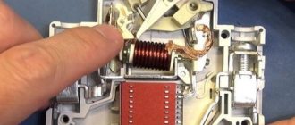
First, let's look at the design of the comb. The product consists of a copper plate placed in plastic insulation that does not support combustion. Special leads extend from this plate, thanks to which the machines in the panel are connected. The number of plates corresponds to the number of poles.
Please note that there are combs with pitches of 18 and 27 mm. The first ones are intended for switching AVs with a width equal to one module. Accordingly, 27 mm is a width of 1.5 modules
Pay attention to this point when choosing a distribution bus for your own conditions!
Based on the number of poles, connecting busbars are divided into single-pole, two-pole, three-pole and four-pole. Each design option has its own purpose. For example, a single-pole comb is used to connect a single-phase circuit breaker, and a four-pole comb, respectively, is used to install three-phase RCDs with 4 poles (three phases and zero).
The number of taps can be from 12 to 60, so the use of combs to connect two electrical machines is not a rational solution. It is advisable to use a distribution bus when assembling large panels.
The taps themselves can be pin (marked pin) or fork (fork). The former are used much more often, because Fork outlets are not suitable for all machines; they require a special clamp.
The last design feature that I would like to talk about is the cross-section of the bends. As a rule, taps are made with a cross-section of 16 mm2, which is quite enough to withstand a current load of 63 A.
Typical errors when connecting circuit breakers
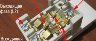
- When installing jumper wires between circuit breakers, it is recommended to use wires of the same size, especially when using rigid single conductors. This is due to the fact that a conductor of a smaller cross-section may not be sufficiently pressed with bolts to the terminal strips.
An example of a machine burning out due to poor contact on jumpers with wires of different sections:
The main force falls on the larger cross-section conductor; the thin wire remains dangling in the terminal hole. As a result of this error, weak contact leads to increased heating and burnout of the circuit breaker. If you make connections with different cross-sections, taking into account the power of the loads and stranded wires, they are evenly pressed into the connecting terminals.
- When purchasing circuit breakers and busbars, be sure to check their suitability. Remember that pin combs are universal, and FORK plugs are only suitable for certain types of machines, indicated above in the text.
Metals used in tire production
Depending on the purpose and required operating parameters, the following can be used for the manufacture of conductors:
- copper;
- aluminum;
- steel;
- steel-aluminum - a steel core covered with a layer of aluminum wires.
The advantages of aluminum tires include anti-corrosion resistance, excellent electrical conductivity, low weight and reasonable cost. For their manufacture, low-alloy aluminum alloys with a low content of silicon and magnesium are used to improve the ductility and strength of the metal.
Copper buses with a copper content of up to 99% are in no way inferior to aluminum ones, but are less widespread due to their relatively high cost.
Application
Zero tires with or without casing allow you to cope with a number of important tasks:
- there is the possibility of forming several points simultaneously, which will allow you to connect loads from the input to zero;
- it is possible to perform visible grounding using a device with a cover made of translucent material, which helps close the terminals;
- there is an increase in the efficiency of using automatic devices of a protective format;
- it is possible to create an unbroken circuit in the zone from grounding to a certain load;
- the condition responsible for separating the wires is met.
Zero bus
Zero tire on DIN rail
The connection of grounding and neutral working conductors is carried out using a zero bus. Its design consists of a conductive core and a plastic base, which is mounted on a DIN rail. The core is made of special electrical copper or brass. The design of the conductive element has holes and clamping bolts. Their presence allows for accurate and safe cabling in switchgear units. Models of zero busbars are made in different lengths, which allows you to make the required number of mounting holes in the core. Their main area of application is AC or DC networks designed for operating voltages up to 400V.
Thanks to the use of a zero bus it will be possible to:
- increase the efficiency of the automatic protective devices used;
- create simultaneously several points for connecting loads to the neutral conductor;
- carefully and safely separate neutral and working conductors;
- perform visible grounding using a plastic device with a cover to protect the terminals;
- install a single circuit from the grounding point to each load.
Installation of the zero bus is carried out directly inside the electrical panel or on a metal rail using a bolted connection. There are open and closed installation methods. The first option is provided for electrical cabinets with a closed structure, which prevents unauthorized persons from accessing the internal contents. Closed installation is optimal for networks to which expensive, energy-intensive equipment is connected - machines and mechanisms, power tools, etc.
Installation of tires on machines
After installing the circuit breakers in the switchboard on the DIN rail for all groups, the bus is simply inserted with the lead-out contacts into the upper connectors of the switches, after which the terminal screws are tightened.
12-16 contacts can be allocated on the busbars; if it is necessary to connect only eight circuit breakers, the busbar can be easily sawed with a hacksaw. To do this, it is better to pull out the metal plate, saw off the required section, insert it into the plastic case and saw it off 5 mm larger. This will prevent the exposed plate from protruding outward. Sometimes side dielectric plugs are used for these purposes.
After installing the bus, in test mode, without applying voltage, you can check the correct connection:
- For a single-phase circuit, turn on all the circuit breakers and check the phase line with a multimeter in continuity mode.
Single-pole bus with fork contacts
Connect the probes to the input of the first and in series to the output of each in the circuit connected to the bus. If there is contact, it means that all comb leads have entered the terminal holes of the corresponding switches and the circuit is operating normally. After checking, you can connect the load lines to the output of the machines.
- In a three-phase circuit, similar actions are carried out with the installation of a three-pole bus.
In this case, the circuit breakers in the line will alternate in phases 1-2-3, every fourth switch will be connected to phase 1, the fifth to phase 2, the sixth to phase 3, and so on in this sequence.
Therefore, the test call must be carried out taking into account this sequence.
- Two-pole and four-pole buses are used when not only phase lines, but also neutral wire lines pass through the switches.
Design features
Upon closer examination of the design, you will notice that it consists of a conductive core and a base made of plastic, which is designed for installation on a DIN rail.
The photo shows the appearance of the NS:
The current-carrying core contains holes and clamping bolts for fixing the conductors in it, as well as for neat and safe wiring of conductors N inside the switchgear. NS differ from each other in both the installation method (housing) and the number of mounting holes, respectively, in length.
To ensure a high-quality connection, as well as simplify further maintenance, the bus is made of a single conductive element of sufficient size made of electrical copper or brass. With a different number of bolt terminals to which neutral (N) conductors are connected.
A distinction is made between ground buses in a housing and grounding buses without a housing; the externally conductive elements are identical. The neutral bus is made in a housing or an insulator is installed. For the correct functioning of differential protection devices, it is necessary to connect them correctly, and to separate the conductors N from PE in the distribution board. In the case of a metal shield, this can only be done by isolating the neutral conductor from the housing.
How to choose a housing for an electrical panel in an apartment or house
Since all the elements from the diagram are installed inside the panel body, it must be selected after developing the installation plan. So that everything you need will fit and there will be some reserve for adding components. The result is a diagram for 42 modules, which means we’ll take the case for 46, or we’ll take 66 places, and we’ll take the cabinet for 72.
The free space will allow you to connect a new line or pair if the need arises. For example, we bought more household appliances, but the cable and sockets in the kitchen/bathroom will not carry the overall load and we need to “throw in” additional ones. Or they changed the stove to a more powerful one and it needs a cable with different characteristics. Therefore, it is better to take a cabinet with a reserve number of modules than to later replace it with a new one and reassemble the entire panel.
When choosing a housing, the space available for connecting wires and connecting groups of machines is also taken into account. During installation, it is necessary to maintain a safe distance between elements. You cannot push them and the wires tightly, compacting them like sprat in a jar.
Metal cabinets are most often wall-mounted and mounted on the wall. They are available in both standard versions with a degree of protection IP 31-43, and moisture resistant with IP 44-54. To assemble a shield in a house or apartment, a standard housing is sufficient; it is unlikely to get exposed to rain or be placed next to water supply pipes. Sealed boxes are useful for installation outdoors and are not of interest to us. There are models of metal cabinets for installation in a niche; if you like metal and want to put the cabinet into the wall, choose this one.
Plastic panels are produced for both wall and niche installation. You can choose a plastic cabinet for small assemblies (in apartments/country houses) and for complex multi-component panels (cottage, country house, large apartment). In terms of strength and IP protection, they are not inferior to metal ones.
The number of modules is the number of elements the size of one module that can fit on the slats. If an element occupies more than one module in width, then fewer elements will fit into the housing. To determine the required number, you need to add up the dimensions of all the circuit elements in the modules, taking into account the margin for the distance between the parts.
Installation Rules
Installation of the simplest terminal to the panel is carried out in a closed or open way. The first option prevents malicious damage to the bus of powerful or important devices, the second method is applicable if there is no risk of damage to the device. Zero blocks with screw connections are fixed to the distribution panel on a DIN rail; additional insulation for grounding is not provided.
The cross-section of neutral and phase conductors is the same. A similar requirement applies to tire parameters: the actual cross-section is considered to be the size of the thinnest sections. When combining a group of ground and neutral conductors, end consumers, after dividing the “PEN” input, are connected to different buses: PE and N.
How to properly connect zero to ground
Incorrect connection of zero to ground can cause tragedy, instead of protection. In a common house input device (IDU), the combined zero must be divided into working and protective conductors. Then the protective zero should be routed to the shields on the floors, and then to the apartments.
This results in a five-wire network:
- 3 phases;
- N;
- P.E.
PE must be connected to the third contact of the sockets. In old houses there is a four-wire network:
- 3 phases;
- combined zero
If the PE conductor is made in the form of an aluminum busbar, then its cross-section must be at least 16 mm², if the copper busbar (brass) is at least 10 mm2. This rule is valid for ASU; otherwise, you should be guided by the table below.
| Section of phase conductors, mm2 | Minimum cross-section of protective conductors, mm2 |
| S≤ 16 | S |
| 16 | 16 |
| S>35 | S/2 |
Circuit breakers and other disconnecting devices cannot be installed on the PE protective conductor; it must be non-switchable. It is necessary to separate the combined PEN zero before the machines and RCDs, after them they should not be connected anywhere!
Forbidden:
- Connect the protective and neutral contacts in the socket with a jumper, because if the zero is broken, dangerous phase voltage will appear on the housings of household appliances;
- connect the neutral and protective conductors with one screw (bolt) on the busbar in the shield;
- PE and N must be connected to different buses, and each wire from each apartment must be screwed with its own screw (bolt). It is necessary to take measures against loosening of bolts and protecting them from corrosion and mechanical damage (clause 1.7.139 of PUE 7).
This connection is used in modern power supply of residential premises or private houses. Which meets the requirements of PEU-7 (clause 7.1.13) for direct and alternating current networks with a voltage of 220/380 volts. After separation, combining them is strictly prohibited.
In a private house, we often receive two or four wires from overhead power lines. Most often there are 2 situations:
Situation #1 is a good case. Your electrical panel stands on a support, and a re-grounding is driven under it. There are two buses PE and N in the electrical panel. The zero from the support and the wire from the grounding conductor go to the PE bus. There is a jumper between the PE and N buses, from the N bus there is a working zero to the house, from the PE bus there is a protective zero to the house. Buses PE and N can be installed in the house in the distribution board, then the neutral is connected to the ground on one bus in the metering board as in the photo below.
The point is to connect the zero and grounding at the input to all RCDs and automatic circuit breakers, and from this point lead the phase, neutral and ground to the consumers.
Such boards are now often assembled when connecting new private houses to the power grid. In this case, the input circuit breaker is installed in phase, the zero from the overhead power line goes directly to the meter, and the division of the zero (connection to the grounding conductor) is made after it. Less often this is done before the meter, but energy sales are often against such a decision. Why? Nobody knows, they argue about the possibility of electricity theft (the question is how?).
Situation No. 2 - The metering board can be either on a support or in the house or on its facade, it doesn’t matter. You have a sealed input machine and a meter, respectively, you have one or three phases and zero. How to make grounding and is it necessary to connect it to zero? If the overhead power line is new, it is necessary. As in the previous case, you will receive a TN-CS system. Then: the zero from the meter is connected to the PE bus, to which is a wire from the ground electrode (which you will make yourself on your site).
If the overhead power line is old, there is no need to connect the neutral and the ground (Chapter 1.7. PUE clause 1.7.59). Make a TT system (without connecting PE to N). In this case, be sure to use an RCD!
In both situations, each wire on the busbars must be tightened with its own bolt - do not put multiple PE or N conductors under one bolt (or screw).
If you live in an apartment, we recommend reading this article: https://samelectrik.ru/kak-sdelat-bezopasnoe-zazemlenie-v-kvartire.html.
Zero bus: types, what it is needed for
As is known, the power supply system for the end consumer is built according to the schemes recommended by the Electrical Installation Rules (PUE). A power cable is supplied to the facility, and further wiring occurs in the distribution panel.
For ease of installation and organization of power supply lines, inputs with different values are combined into contact groups.
A bus with a phase, a zero bus is a contact block in which there is the ability to reliably connect several conductors to power electrical installations.
Requirements for the zero bus
For a group network, the bus must be a single conductor, without the possibility of switching between its parts. The resistance should be the same along the entire length. Within one group line, it is allowed to combine conductors PE (protective grounding) and N (working zero). Moreover, after dividing the PEN input into PE and N buses, end consumers are connected to different buses. Important! Using one bus to connect the working zero and grounding is prohibited! This is a fundamental issue, it is necessary to understand the difference between separation and combination of PE and N. From the moment of separation, the ground and neutral lines can be laid in the same power cable, but the conductors must be insulated. Regardless of the connection method (three-phase or single-phase), the cross-section of the neutral conductor must correspond to the cross-section of any of the phase conductors. The same requirement applies to the cross-section of the tire itself. The cross-section of the connecting wires from the bus to the final electrical installation cannot be higher than the cross-section of the input power wire. If the bus is a structure with holes for connecting conductors, the actual cross-section is considered to be the geometric parameters in the thinnest part. There are no requirements for the mandatory production of a zero working tire from a specific metal
However, in practice, copper or brass is used. When calculating the cross-section of aluminum busbars in relation to copper busbars, a coefficient of 1.52 is applied.
For convenience, we will consider a single-phase circuit, which is used in most apartments in multi-storey buildings. Two main lines: phase and zero, are always present. They are inserted into the meter (electricity meter), and at the output they become available for further wiring. Depending on the system used, either only a zero bus or a zero and ground bus can be installed.
Floor panel without working zero bus (+photo) ???
Everything is correct...., at least in the installation of the shield...
It's like no? If there are 5 feeders in the riser... The protective zero (PE) is brought out on the panel body, and the working neutral (N-neutral) must then be taken from the nut - if there is only one apartment, then it makes no sense to make its bus, since it must go through the input four-pole circuit breaker. If there are several apartments, then they still take several wires from walnut... (If there are circuit breakers from builders in the panel, then they need to be hit in the face... since they installed three-pole ones - and according to the rules, the zero should also be turned off)
That's right... only for correct dialing you will have to turn off both phases and zero
So I say that it looks like they forgot to take the neutral from the nut.... or when connecting the shield they simply lost it...
When you turn on the device, the RCD will immediately trip.
Rule!!! — PE (ground, protective neutral conductor) and N-neutral are different wires and are not connected anywhere you can see it. (They are connected at the input of the house, or even further - at the transformer substation - believe me, it’s necessary and it’s safe...)
Don't bother your head with nonsense. No one will confuse and nothing will end up anywhere. Only you and your electricians can do this at the entrance or inside the apartment...
Be sure to mark the wires with heat-shrinkable tubes of the appropriate colors (or electrical tape, but it will fall off later) + mark where they go. Since there is, of course, it will work, but you ordered the shield in accordance with the PUE, and not hack work...
Where are the machines and wiring of other apartments? Maybe they have separate risers?
Benefits of using busbar trunking
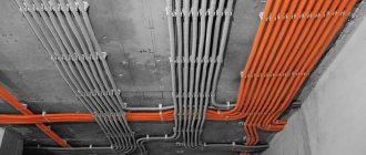
An electrical bus is more convenient to use than a group of wires
The use of busbars in electrics instead of cable products provides significant savings in material, energy and labor resources:
- Installation takes 2 times less time than cable laying.
- Service life – up to 30 years without the need for complex maintenance.
- The flexible configuration allows for high-quality and safe installation of the network, depending on the route it runs.
- The busbar has a more aesthetic appearance than group wiring.
- Shielding the conductor eliminates the impact of the electromagnetic field on nearby office equipment.
- The design is fireproof and meets safety requirements for IP55 protection level.
Online home handyman assistant
When operating an electrical network of 400 volts, one cannot do without special protection - grounding conductors and working zeros, which are connected through the zero bus. Without it, assembling a complete electrical panel that meets all safety parameters is impossible, so it is important for every owner of a high-voltage line to know the details of installing the zero bus with their own hands.
More details about the appointment
Using a grounding zero bus in the wiring system allows you to solve many important issues:
- Creation of several points to share the total load from the main input to the neutral conductor.
- “Opening” the grounding mechanism through the use of a transparent cover in the design that protects the terminals.
- Increasing the efficiency and performance of automatic protection devices.
- Ensuring line continuity from direct grounding to the output point.
- Saving space in the panel, since there will be no need to place several single tires.
- Separation of neutral and phase wires.
In general, the zero bus allows you to raise the security of the network to a qualitatively new level, however, its use and connection must be as competent as possible, therefore special requirements are imposed on the installation of this element of the electrical network.
Rules for installing and connecting the contact strip
Such a terminal block can be installed in any easily accessible place in the power cabinet. The zero bus is connected in the panel as follows. An incoming zero is supplied to the fixed strip. The contact is firmly fixed. After this, all neutral wires going to apartment groups are clamped into terminals. From the zero bus they go directly into the premises or to residual current devices (RCDs) or residual current circuit breakers (RCBOs).
It is important that the bar is tightly fixed. Otherwise, it will not be possible to properly stretch the zero contacts, which will lead to an increase in temperature at the connection point. In this case, just one loosely fixed contact will lead to heating of the entire strip, which will lead to weakening of the remaining connections.
Characteristics
When choosing the necessary zero buses, it is worth presenting clear requirements for the design. The main thing is the cross-section of the wire. Guided by the clear rule “the cross-section of the wire does not exceed the cross-section of the main grounding bus,” you can provide high-quality power supply and save money on maintenance in the future.
The characteristics of the zero bus vary depending on the type of installation. There are two types of devices according to the distribution scheme that meets the requirements of the PUE:
In the first case, a grounded bus, which is a tightly grounded neutral, in which connection to the protective ground is provided exclusively at this point. Further, only two busbars are inserted into the shield along the insulated conductors. This scheme is considered the safest, since the neutral and grounding buses are separated directly at the entrance of the device into the room.
The second option presents an outdated but popular TN-C type circuit. In this case, the grounding is not represented by a separate conductor, but in the panel itself there is only a zero bus. Here, too, you cannot connect ground and zero. Therefore, here the concept of “earth” in its usual representation is not present.
Form of conclusions
The most common are comb buses with pin taps (pin type combs). The English name is pin. They fit most modern circuit breakers. The terminals of such tires are more difficult to bend during transportation. Therefore, during installation there are fewer problems with installing circuit breakers into the holes.
The second type of bends is fork-shaped (fork type). They are used relatively less frequently. Not suitable for all types of modern equipment. Connecting bars with forked terminals are not recommended for use with powerful loads. Usually they are placed in a panel with a maximum current of up to 63 A.
Double-pole fork-shaped comb
Briefly about the design and operating principle
If you look closely at the photo of the zero bus, you can see a conductor made of electrical copper or brass on a plastic base. Each mini busbar is separated from its neighbor by a transparent plate, ensuring safety and insulation.
The holes and clamping bolts in the structure are designed to secure conductors and route them safely, and the device is fixed to a DIN rail using a plastic housing.
The length of the product depends on the number of mounting holes available, however, despite the difference in the clamping bolts, the tire is always monolithic, which simplifies maintenance and increases the safety and reliability of fastenings.
Also, grounding buses differ in the presence of the housing:
Zero tires with a body inside do not differ from their “bare” counterparts, but are externally enclosed in a special plastic block, which in most cases is made of opaque white plastic on three sides, and with a transparent bluish cover on the front side.
It is easy to identify this grounding device in the shield not only by its oblong shape, but also by the obligatory presence on the body or base of a blue or light blue color - a clear indicator of the zero type of the electrical network element.
Secrets and standards of installation
When installing the zero bus, one of several possible types of installation can be used (the appropriate one is prescribed in the instructions):
- On an insulator, screwed in the center or along the edges;
- Screw;
- On DIN rail;
- On G-rail.
In turn, zero bus insulators can be absent or can be case-type, “rack” type, combined, single or double corner (“leg” type).
Installation can also be closed (for example, for powerful or important equipment, to exclude the possibility of malicious damage to the tire) and open (when there is no risk of hacking or damage to the unit).
Below are detailed instructions on how to connect the zero bus, accompanied by step-by-step photographs:
What is a Power Cable?- How to conveniently unwind a cable coil on site during electrical installation
Electrical cables. Purpose and selection criteria
- Familiarize yourself with the appropriate panel connection diagram, find the zero bus in the image (the icon repeats the general appearance of the device marked “N”).
- De-energize the electrical panel by unscrewing all existing plugs or placing the circuit breakers in the inoperative position.
- Check that there is no voltage by holding an indicator screwdriver or multimeter to the input conductors.
- Determine the location for placing the bus depending on its design features (if fixation to special strips is provided, then install the necessary ones in the panel; if not, fasten them through insulators to a free place).
- Install the strip on the DIN or G using special clamps, or directly into the panel using a screw type of installation from the center or sides (where the insulator is located).
- Check the reliability of the fastenings by trying to “loose” the installed structure.
- Connect the conductor coming from the residual current device to one of the busbar clamping bolts.
- If the circuit has two or more protective connection devices, then each of them is connected in series to the bus.
- Connect the neutral conductors coming from the circuit breakers of each branch of the network to the corresponding terminal of the neutral protective device.
- Connect the common “zero” of the network to the outer terminal on the zero bus.
- Check the correctness and quality of all connections made.
- Turn on the electricity supply.
During work, it is important to follow the safety rules:
- Install only when there is no current in the conductors;
- Use special clamps, terminals, and not homemade “twists”;
- Ensure good contact of the wires, if necessary, trim and strip their ends;
- Do not allow wires to overlap, twist, break or bend;
- Do not neglect marking conductors in any available way (color, signature, signs).
The zero line is an integral part of any electrical network, so it is important to properly organize its functioning inside the panel. The zero bus will provide order and the possibility of sequential connection of all contacts to ensure safe, comfortable and complete use of electricity.
Specifications
The grounding bus must be installed inside the electrical panel and connected to the current grounding circuit.
Due to its basic technical characteristics, such an element is used as a conductor between the grounding system and the plug part of the technical installation. Inside the input devices, as a rule, grounding buses of the “PE” type are used.
Ground bus with ground wires
In such conditions, the grounding conductor must have the appropriate cross-section:
- copper conductors - 1.1 cm or more;
- aluminum conductors - about 1.7 cm or more;
- steel conductors - 7.5 cm or more.
The cross-sectional parameters of the installed grounding bus must correspond to the parameters of the conductor.
| Tire type | Conductor cross-section | Current | Number of holes for fasteners | Number of clamps | Dimensions |
| RE 6/1 | 1.5-16 mm2 | 63 A | 1 | 6 | 6x9x46 mm |
| RE 8/1 | 1.5-16 mm2 | 63 A | 1 | 8 | 6x9x58 mm |
| RE 8/2 | 1.5-16 mm2 | 63 A | 2 | 8 | 6x9x64 mm |
| RE 10/2 | 1.5-16 mm2 | 63 A | 1 | 10 | 6x9x70 mm |
| RE 10/1 | 1.5-16 mm2 | 63 A | 2 | 10 | 6x9x76 mm |
| RE 12/1 | 1.5-16 mm2 | 63 A | 1 | 12 | 6x9x82 mm |
| RE 12/2 | 1.5-16 mm2 | 63 A | 2 | 12 | 6x9x89 mm |
| RE 14/1 | 1.5-16 mm2 | 63 A | 1 | 14 | 6x9x95 mm |
| RE 14/2 | 1.5-16 mm2 | 63 A | 2 | 14 | 6x9x102 mm |
| RE 16/1 | 1.5-16 mm2 | 63 A | 1 | 16 | 6x9x107 mm |
| RE 16/2 | 1.5-16 mm2 | 63 A | 2 | 16 | 6x9x114 mm |
| RE 18/1 | 1.5-16 mm2 | 63 A | 1 | 18 | 6x9x119 mm |
| RE 18/2 | 1.5-16 mm2 | 63 A | 2 | 18 | 6x9x126 mm |
| RE 20/1 | 1.5-16 mm2 | 63 A | 1 | 20 | 6x9x132 mm |
| RE 20/2 | 1.5-16 mm2 | 63 A | 2 | 20 | 6x9x138 mm |
| RE 24/2 | 1.5-16 mm2 | 63 A | 2 | 24 | 6x9x163 mm |
The grounding bus can be of the zero working type “N” and the protective type “PE”, but the installation of such a device must be carried out by specialists, which will make the operation not only durable, but also safe.
Where to start?
Every experienced electrician will confirm that it is much easier to begin work on installing an electrical panel and wiring, having before your eyes a floor plan indicating the intended placement of household appliances, lighting fixtures, as well as sockets and junction boxes. Having decided on the number and power of consumers, it is necessary to draw up a diagram of the electrical panel itself. A single line diagram might look like this:
In this diagram, all consumers are divided into 20 groups, for each of which the following is indicated:
- wire grade and core cross-section, mm²;
- power;
- current consumption;
- type of circuit breaker indicating the rated current.
For the uninitiated, such a diagram looks quite complicated, so you can use a simplified schematic representation of the location of the electrical panel components.
For greater clarity, the electrical panel diagram can be depicted as follows:
Or even like this:
Where
- 1 - introductory AB;
- 2 - counter;
- 3 - zero bus;
- 4 - grounding bus;
- 5–10 — AV consumers.
Having such a diagram in hand, it is much easier to figure out how to properly assemble an electrical panel.
Installation Rules
Installation of the NS is possible both on a special rail and in an electrical panel. Installation options are available in both closed and open ways. The open method is perfect for a cabinet that will be closed to unauthorized persons. The closed version is used in situations where equipment is used that is connected to very important elements. An example is a power socket for various electrical tools.
The video below clearly shows how to install the NS on a DIN rail and how to fix it more reliably:
So we looked at the structure and purpose of the zero bus. We hope the information was useful and interesting for you!
You probably don't know:
- What is GZSh in electrical engineering?
- Why do you need a cross module?
- What is the danger of a broken neutral wire?
Which manufacturer to choose
In fact, preference for one logo over another is not related to quality. Accessories for installing electrical wiring are produced by all well-known electrical companies. And if your entire socket network, circuit breakers and wiring are manufactured by IEK, ABB, Legrand or Schneider Elerctric, it makes sense to buy zero rails and protective earth buses with the same logo.
Extremely cheap “noname” products can simply crack during operation, causing guaranteed problems for expensive electrical equipment.
It is better to make two zero tires in the shield!
28 Jan 2022 Assembly of shields
Hello everyone, today is an article on practical experience in assembling electrical panels from experienced electrician Sergei Panagushin from Izhevsk. We will talk about such a nuance as installing zero busbars in the shield; Sergey will tell you how best to do it so that the contact of the busbar with the wires is the best.
If it’s not difficult for you, vote for this article by Sergei here - https://vk.com/wall-125051812_548
Just like it.
So, word from Sergei:
Hello dear reader! In today’s article I would like to share a couple of tricks that can be used when installing automatic machines and zero tires in the dashboard.
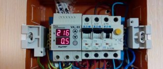
So: it is best to install tires not one at a time, but two at a time, as shown in the photo.
Why is this being done? Everything is very simple: with such an installation, the contact area increases and the connection is duplicated, and if under one screw the contact loosens, that is, the second contact and such a contact point will not heat up, which reduces the risk of failure of the electrical supply system.
When installing busbars on circuit breakers, the insulated part can be wrapped with insulating tape instead of using end caps. This can be seen in the photo.
You don’t need to wrap a lot of insulating tape, just 1.5-2 turns is enough; if you do more, the busbar will not fit completely into the terminals of the machine, which can also have a detrimental effect on the operation of the electrical supply system. This is done in order to avoid causing an accident if work has to be done on the panel with partially relieved voltage.
PS I also sometimes use insulating tape as a tire heating indicator. For example, in the switchboard, we wrap insulating tape around the bus and periodically, when taking readings in the electrical switchboard, we look at the condition of the insulating tape
If it begins to shrink, then this indicates that there is heating in this place and you need to figure it out... Thank you for your attention!
Video from Sergei Panagushin:
Assembly of a 1-phase shield: Instead of an RCD, a difavtomat. 4 differentials for 4 groups.
Crazy hands: “comb” made of wire:
Crazy hands: Zero tire bulkhead:
Jumper wires
Electricians usually make jumper wires themselves. Any single-core insulated wire of suitable cross-section is suitable for making jumpers.
It is recommended to use single-wire wire PV-1 or multi-wire (flexible) wire PV-3 in vinyl insulation.
The process of making jumpers is simple. First, the length of the conductor is measured and the required number of wire segments is cut. The wires are stripped at both ends. The length of the bare part of the wire should be 12mm. Then the wire is bent, giving the jumper the desired shape. If a flexible wire is used, lugs are pressed onto the bare ends using press pliers.
An example of connecting machines using jumpers.
The cross-section of the wire for making jumpers must be selected based on the sum of the rated currents of all circuit breakers connected to the first circuit breaker in the loop.
To ensure high-quality contact, it is desirable that the ends of the jumpers connected to one terminal of the machine have the same cross-section.
Often electricians make jumpers between machines from one continuous wire. The appearance of such a jumper attached to the machines is shown in the figure below.
Connecting machines using jumpers has its advantages and disadvantages.
The disadvantages of this connection method include:
High complexity of manufacturing jumpers. This is especially noticeable with large volumes of electrical installation work.
If the DIN rails are located close to each other in the panel, the jumpers may interfere with the connection of conductors to the circuit breakers of the top row.
The advantages of using jumpers include low manufacturing costs. If the jumpers are made of unbreakable wire, then it is possible to replace a failed circuit breaker without turning off other circuit breakers.
To do this, disconnect the jumpers from the upper terminals of the machine, put pieces of insulating tube on them, remove the faulty device from the DIN rail and install a new one. Then connect the power wires.
Installation
There are several ways to organize the installation of a grounding bus, but the most popular are installation in an electrical panel and outside the cabinet.
Panel mounting
Cabinets with an installed bus can be placed on the facade of the household or in a special, separate panel room. For outdoor or outdoor installations, shields are suitable, the body of which is marked with the IP index. Installation of a grounding device involves the following activities:
- fixing the main grounding bus with a bolted connection on the body of the steel shield;
- connecting the protective element to the zero rail using a jumper made of steel or copper;
- The dimensions of the installed element must be comparable to the cross-sectional indicators of the “protection” and “zero” conductors.
Grounding diagram
It should be noted that the rules for placing the grounding bus and other elements inside the electrical panel are not specified in regulatory documents.
The PE copper grounding plate installed inside the shield must have a minimum cross-section of 10 mm2, and the steel one - at least 75 mm2.
Installation outside the panel
External installation of the grounding bar is carried out in areas that have sufficient protection from unauthorized access by unauthorized persons. Fixation is carried out with durable insulators.
Assembly and installation of electrical panels. Cable connection diagram
The most convenient options for external arrangement of the grounding bus include the use of special DIN rails.
A fairly common method used to connect individual elements of the grounding bus is welding, which fully complies with all GOST requirements for arranging reliable and safe contacts.
Connecting single-phase devices
Single-phase connection is the simplest. It is used for single-pole machines. The procedure is as follows:
- All protection devices are installed in a row. This requires a DIN rail.
- For each individual device, the screws in the terminal blocks are loosened to a certain point. This is done from the top side.
- One single-pole bus is inserted into the terminal blocks of circuit breakers. The pitch of its teeth should be 17.5 mm.
- The screws are tightened. The tightening is tight enough to securely fix the tire pins.
Electrical busbar markings
Marking of zero tires
The application of color markings to electrical busbars is regulated by current standards. Compliance with their requirements is mandatory for every manufacturer. Marking can be applied both at the production stage and after its completion. In the first case, colored insulation is used, in the second, colored insulating tape is used, indicating different phases of the conductor.
The color designation of tires allows you to accurately determine their type and purpose:
- The grounding conductor is marked in yellow and green in the form of alternating longitudinal stripes.
- Neutral and working conductors are indicated using blue color.
- Connecting conductors involves using all three shades in different versions: insulation with longitudinal yellow and green stripes and a blue line at the end, or blue insulation with a yellow-green stripe at the joints and at the ends of the conductor.
According to the requirements of current standards, along with the color marking of conductors for alternating current networks, the following letter designation of conductors is used:
- in a single-phase network – L;
- in a three-phase network - L with numbers from 1 to 3;
- medium – M;
- neutral, or zero – N;
- grounding – PE;
- combined working and neutral - PEN (combination of the designations of each of the conductors used).
Models for DC networks are marked with the letter L with a + or - sign, respectively - a positive or negative conductor.
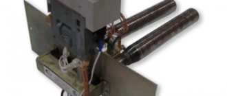
Transformer types
There are different types of step-down TN. The usual and most common is single-phase for a 220 V network. There are also two- and three-phase for 380 V. The most standard composition: two windings and a laminated core made of electrical steel.
Certain types of VTs are equipped with 1 winding - these are autotransformers, they can also step down / step up. In this case, there are at least 3 conclusions. A 220 V connection is made to one pair of contacts, and the output value is taken from one of the input pairs of terminals and from the other that remains free. But autotransformers cannot be used in wet rooms, since the coils in them are connected, that is, the consumer is also connected to 220 V.
How to connect several machines
The choice of circuit is determined by the characteristics of a particular electrical network. The easiest way is to install one RCD immediately after the meter. A safer option is to connect protective devices on individual lines. If one device fails, the others will remain in working order. The implementation of the second scheme requires the use of a marker panel.
Simple scheme
Using an example, it is convenient to consider a single-phase circuit used for most apartments in multi-storey buildings. A two-pole circuit breaker is installed at the input, connecting the RCD. Bus “0” in the electrical panel is marked “N”. A two-pole residual current device is connected to two single-pole circuit breakers. The output of individual machines allows you to connect loads in parallel.
The phase connected to the circuit breaker enters the input of the RCD with output to the switches. The zero output from the machine is sent to the corresponding bus, then to the input of the connected device. The neutral wire coming out of the consumer equipment is directed to the second neutral terminal. The presence of an additional bus “0” allows the RCD to control the incoming and outgoing voltage.
If two RCDs are connected, three brass blocks will be required: the main zero bus marked N1 and bars N2, N3 for residual current devices. The RCD is grounded to an additional element of the electrical panel - bus “P”.
Distribution panel composition
The distribution panel consists of the following elements:
The meter allows you to determine the amount of electricity consumed. It is installed by energy company employees who seal the device. The main switch completely cuts off power to the panel
. It is usually two-pole and disconnects the phase and neutral wires supplying electricity. Its power must correspond to the sum of the powers of all energy consumers included in the apartment.
An interesting and educational video about the secrets of choosing machines and assembling a switchboard with your own hands:
Dimensions and types of electrical panels
Having calculated the number of components and drawn a diagram of the electrical panel, you need to take care of where all these elements will be installed. It's time to buy a cabinet that will fit all the necessary electrical equipment. First of all, we determine the exact location of the electrical panel. The type of cabinet will depend on the location. For example, if the shield will be installed outdoors, you will need a moisture-proof cabinet; if indoors, you can get by with a regular one.
The following types of electrical panels are distinguished:
- plastic and metal;
- wall-mounted and built-in;
- collapsible and solid;
- with a large and small number of places;
- with a solid and transparent door;
- with and without locking mechanisms.
Also, cabinets for household electrical panels differ in size and shape. The cabinet should be selected according to the location and amount of electrical filling, but if you have a choice, take a large panel. A larger panel is easier to work with and will provide extra space in case you ever decide to upgrade your electrical system.
The size of the panel is determined not only by the dimensions of the cabinet itself, but also by the number of spaces for single-pole circuit breakers with a thickness of 12 mm. Consider the fact that your circuit will contain not only single-pole, but also double-pole circuit breakers, which are twice as thick. In general, in order to correctly calculate the number of required spaces in a future cabinet, you will need to know the dimensions of all the machines used in the circuit. But this is not particularly difficult, since most often their sizes are standard.
Let's give an example in which you can see how many spaces in the panel a particular module will take up.
- A single-pole machine will take 1 place.
- A two-pole machine will take up 2 spaces.
- Three-pole machine - 3 places.
- Single-phase RCD – 2 places.
- Three-phase RCD – 4 places.
- Single-phase automatic circuit breaker – 2 places.
- Tire – 1st place.
- Modular socket – 3 places.
- Voltage relay – 3 places.
- Modular electric meter – from 6 to 8 places.
What is a module in a shield
The module in the distribution board is a place for installing one single-phase circuit breaker. Each shield is sold for a certain number of modules. Before purchasing a shield, you must know exactly how many and what kind of machines you will have in the shield. Convert machine guns into modules, add 6-9 modules to the stock and buy the corresponding shield.
To convert equipment into modules, use this hint:
- a two-pole circuit breaker is a module,
- Single-phase RCD three modules,
- Three-phase RCD five modules,
- three-phase machine three modules,
- three-phase differential circuit breaker six to eight modules.
DIY assembly steps and rules
Before you start assembling a 220 V or 380 V electrical panel with your own hands, you must create all the conditions for comfortable work. It is necessary to check the availability of tools and a complete set of equipment, fasteners, and cable products. Prepare a flashlight with a charged battery. You need to check the circuit and determine the correspondence of the picture with the wires laid out.
The panel installation work is divided into several stages:
- Preliminary work. These are all operations in direct preparation for the installation of an electrical panel. To do this: Remove the plugs and drill additional holes (if necessary).
- The door and wall panels that will interfere are dismantled. All rails and terminal block are installed.
- Hinges are screwed in for installation.
The cables must be connected in order. From which side this is done does not matter. You need to follow some rules:
- When installing an electrical panel with your own hands, all wires are laid horizontally and vertically.
- Bends - at an angle of 90 degrees.
- The veins are exposed by about 10 millimeters.
- The lugs are crimped onto the flexible wire.
- All connections are pulled tight.
- According to unwritten rules, the input is connected from above, consumers from below.
- Unstripped areas of wires should not be clamped into terminal blocks.
- For ease of installation and subsequent operation, groups of wires must be assembled into bundles and secured with plastic clamps.
Power is connected to the input device after the voltage has been completely removed and checked with an indicator. The cores are pulled tightly onto the terminals. If there is a ground, the contact is connected to a separate terminal block. After the introductory machine, the metering device is connected and then in groups.
At the final stage of assembling electrical panels, it is necessary to visually check the correctness of all connections, the absence of unnecessary wires and the quality of the contacts, by tugging them with your hand. After this, food is supplied to each group in turn. RCD testing is carried out by pressing a button and checking that there is no power in the corresponding group. If no problems are identified or after they have been eliminated and rechecked, all removed parts are returned to their place and the voltage is switched on to full load.
Correct installation and selection of appropriate components guarantees trouble-free operation of the residential energy system. Not only comfortable living, but also the safety of human health and even human life depends on this.