Application area. Definitions
7.1.1.
This chapter of the Rules applies to electrical installations of: residential buildings listed in SNiP 2.08.01-89 “Residential Buildings”; public buildings listed in SNiP 2.08.02-89 “Public buildings and structures” (except for buildings and premises listed in Chapter 7.2): administrative and domestic buildings listed in SNiP 2.09.04-87 “Administrative and domestic buildings” ; Additional requirements may apply to electrical installations of unique and other special buildings not included in the above list. Further in the text, unless otherwise specified, the word “buildings” means all types of buildings to which this chapter applies.
The requirements of this chapter do not apply to special electrical installations in medical institutions, organizations and institutions of science and scientific services, to dispatch and communication systems, as well as to electrical installations, which by their nature should be classified as electrical installations of industrial enterprises (workshops, boiler rooms, thermal points, pumping stations, laundry factories, dry cleaning factories, etc.).
7.1.2. Electrical installations of buildings, in addition to the requirements of this chapter, must meet the requirements of the chapters of Section. 1-6 PUE to the extent that they are not changed by this chapter.
7.1.3. Input device (ID) is a set of structures, devices and instruments installed at the input of the supply line into the building or its separate part.
The input device, which also includes devices and devices of outgoing lines, is called an input distribution device (IDU).
7.1.4. The main distribution board (MSB) is a distribution board through which the entire building or its separate part is supplied with electricity. The role of the main switchboard can be performed by an ASU or a low voltage switchboard of a substation.
7.1.5. Distribution point (DP) is a device in which protection devices and switching devices (or only protection devices) are installed for individual electrical receivers or their groups (electric motors, group panels).
7.1.6. A group panel is a device in which protection devices and switching devices (or only protection devices) are installed for separate groups of lamps, plug sockets and stationary electrical receivers.
7.1.7. Apartment panel - a group panel installed in an apartment and designed to connect the network that supplies lamps, plug sockets and stationary electrical receivers of the apartment.
7.1.8. Floor distribution panel is a panel installed on the floors of residential buildings and intended to supply power to apartments or apartment panels.
7.1.9. Electrical room - room. accessible only to qualified service personnel, in which VU, ASU, main switchboard and other distribution devices are installed.
7.1.10. Supply network - a network from a substation switchgear or a branch from overhead power lines to the VU, ASU, main switchboard.
7.1.11. Distribution network - a network from the VU, ASU, main switchboard to distribution points and switchboards.
7.1.12. Group network - a network from panels and distribution points to lamps, plug sockets and other electrical receivers.
Conclusion
The switch handle sticking out of the switchboard has become a definite feature of old electrical distribution networks. But recently, switches are used less and less. After all, their main advantage, price, has become less and less important lately.
Automatic machines are more functional, safer, less cumbersome and easy to use, so they are slowly but surely winning places in switchboards from circuit breakers. After all, everywhere you can install a machine instead of a switch, but it is not always possible to install a switch instead of a machine.
General requirements. Electricity supply
7.1.13. Electrical receivers must be powered from a 380/220 V network with a TN-S or TN-CS grounding system.
When reconstructing residential and public buildings with a network voltage of 220/127 V or 3 x 220 V, the network should be switched to a voltage of 380/220 V with a TN-S or TN-CS grounding system.
7.1.14. External power supply to buildings must meet the requirements of Chapter 1.2.
7.1.15. In dormitories of various institutions, in schools and other educational institutions, etc. the construction of built-in and attached substations is not allowed.
In residential buildings, in exceptional cases, it is allowed to place built-in and attached substations using dry-type transformers in agreement with state supervisory authorities, while sanitary requirements for limiting noise and vibration levels must be fully met in accordance with current standards.
The construction and placement of built-in, attached and free-standing substations must be carried out in accordance with the requirements of the chapters of Section. 4.
7.1.16. It is recommended that power and lighting electrical receivers be powered from the same transformers.
7.1.17. The location and layout of transformer substations must provide for the possibility of round-the-clock unhindered access to them for personnel of the energy supply organization.
7.1.18. Power supply for safety lighting and evacuation lighting must be carried out in accordance with the requirements of Chapter. 6.1 and 6.2, as well as SNiP 23-05-95 “Natural and artificial lighting”.
7.1.19. If there are elevators in the building, which are also intended for transporting fire departments, their power supply must be provided in accordance with the requirements of Chapter. 7.4.
7.1.20. Electrical networks of buildings must be designed to power advertising lighting, shop windows, facades, illumination, outdoor, fire-fighting devices, dispatch systems, local television networks, light indicators of fire hydrants, safety signs, bell and other alarms, light fencing lights, etc., in in accordance with the design specifications.
7.1.21. When supplying single-phase consumers of buildings from a multiphase distribution network, it is allowed for different groups of single-phase consumers to have common N and PE conductors (five-wire network) laid directly from the ASU; combining N and PE conductors (four-wire network with PEN conductor) is not allowed.
When supplying single-phase consumers from a multiphase supply network with branches from overhead lines, when the PEN conductor of the overhead line is common to groups of single-phase consumers powered from different phases, it is recommended to provide protective shutdown of consumers when the voltage exceeds the permissible limit, arising due to load asymmetry when the PEN breaks conductor. The disconnection must be carried out at the entrance to the building, for example, by influencing the independent release of the input circuit breaker using a maximum voltage relay, and both the phase (L) and neutral working (N) conductors must be disconnected.
When choosing devices and devices installed at the input, preference, other things being equal, should be given to devices and devices that remain operational when the voltage exceeds the permissible voltage, arising due to load asymmetry when the PEN or N conductor breaks, while their switching and other performance specifications may not be met.
In all cases, it is prohibited to have switching contact and non-contact elements in PE and PEN conductor circuits.
Connections that can be disassembled with a tool are allowed, as well as connectors specially designed for this purpose.
Connection diagram
The input switch is used not only for electrical safety, but also to disconnect the consumer from electricity during repair work. For this reason, the machine is installed in front of the meters.
Only a professional electrician has access to the machine. Apartment owners have no right to interfere with the security system. In 90% of cases, the machine is installed in the entrance panel in apartment buildings and in external systems (poles, fences) for cottages.
Owners can install a backup machine, which is used for ease of maintenance. It is placed between the meter and group automation inside the apartment switchboard. The current strength of the backup device should be lower than that of the input device.
Input devices, distribution boards, distribution points, group boards
7.1.22. A VU or ASU must be installed at the entrance to the building. One or more VU or ASU may be installed in a building.
If there are several economically separate consumers in a building, it is recommended that each of them install an independent VU or ASU.
The ASU is also allowed to supply power to consumers located in other buildings, provided that these consumers are functionally connected.
For branches from overhead lines with a rated current of up to 25 A, the VU or ASU may not be installed at the inputs to the building if the distance from the branch to the group panel, which in this case performs the functions of the VU, is no more than 3 m. This section of the network must be carried out with a flexible copper cable with with a conductor cross-section of at least 4 mm2, flame retardant, laid in a steel pipe, and the requirements for ensuring a reliable contact connection with the branch wires must be met.
For air input, surge suppressors must be installed.
7.1.23. Before entering buildings, it is not allowed to install additional cable boxes to separate the service scope of external supply networks and networks inside the building. Such separation must be carried out in the ASU or main switchboard.
7.1.24. VU, ASU, main switchboard must have protection devices on all inputs of supply lines and on all outgoing lines.
7.1.25. Control devices must be installed at the input of supply lines to the VU, ASU, and main switchboards. On outgoing lines, control devices can be installed either on each line, or be common to several lines.
A circuit breaker should be considered as a protection and control device.
7.1.26. Control devices, regardless of their presence at the beginning of the supply line, must be installed at the inputs of the supply lines in retail premises, utilities, administrative premises, etc., as well as in consumer premises that are administratively and economically isolated.
7.1.27. The floor panel must be installed at a distance of no more than 3 m along the length of the electrical wiring from the supply riser, taking into account the requirements of Chapter. 3.1.
7.1.28. VU, ASU, main switchboard, as a rule, should be installed in electrical switchboard rooms accessible only to maintenance personnel. In areas prone to flooding, they should be installed above the flood level.
VU, ASU, main switchboard can be located in rooms allocated in operational dry basements, provided that these rooms are accessible to maintenance personnel and are separated from other rooms by partitions with a fire resistance limit of at least 0.75 hours.
When placing VU, ASU, main switchboards, distribution points and group panels outside electrical switchboard rooms, they must be installed in places convenient and accessible for maintenance, in cabinets with an enclosure protection degree of at least IP31.
The distance from pipelines (water supply, heating, sewerage, internal drains), gas pipelines and gas meters to the installation site must be at least 1 m.
7.1.29. Electrical switchboard rooms, as well as VU, ASU, main switchboards, are not allowed to be located under toilets, bathrooms, showers, kitchens (except for apartment kitchens), sinks, washing and steam rooms of bathhouses and other rooms associated with wet technological processes, except in cases where Special measures have been taken for reliable waterproofing to prevent moisture from entering the premises where the switchgear is installed.
It is not recommended to lay pipelines (plumbing, heating) through electrical rooms.
Pipelines (plumbing, heating), ventilation and other ducts laid through electrical switchboard rooms should not have branches within the room (with the exception of a branch to the heating device of the switchboard room itself), as well as hatches, valves, flanges, valves, etc.
Laying gas and pipelines with flammable liquids, sewerage and internal drains through these premises is not permitted.
Doors to electrical rooms must open outward.
7.1.30. The premises in which ASUs and main switchboards are installed must have natural ventilation and electric lighting. The room temperature should not be lower than +5 oC.
7.1.31. Electrical circuits within the VU, ASU, main switchboard, distribution points, group panels should be made with wires with copper conductors.
What parameters are used to select an input device?
The choice of introductory machine is carried out taking into account a number of features. You need to know them in order to choose the right VA for a specific electrical network:
- Maximum short circuit current. If you choose a device for a country house or a rural house, then in most cases a breaking capacity of 4.5 MA will be sufficient. For an ordinary city apartment, a 6 MA device is suitable. If there is a substation near your car, you should set the car to 10 MA.
- Operating current. We described above how to calculate it. Based on the obtained value, the rated current VA is selected.
- Time-current characteristic. The most common devices are classes B, C and D. Type B switches are installed if there are no high-power devices included in the circuit. If medium-power devices (for example, a welding machine) are periodically connected to the network, a class C device is installed at the input. If high-power equipment is used, the input device must be type D.
Electrical wiring and cable lines
7.1.32. Internal wiring must be carried out taking into account the following:
1. Electrical installations of different organizations, separate administratively and economically, located in the same building, can be connected by branches to a common supply line or fed by separate lines from the ASU or main switchboard.
2. It is allowed to connect several risers to one line. On branches to each riser supplying apartments in residential buildings with more than 5 floors, a control device combined with a protection device should be installed.
3. In residential buildings, lamps in staircases, lobbies, halls, floor corridors and other indoor premises outside apartments must be powered via independent lines from the ASU or separate group panels powered from the ASU. Connecting these lamps to floor and apartment panels is not allowed.
4. For staircases and corridors with natural light, it is recommended to provide automatic control of electric lighting depending on the illumination created by natural light.
5. It is recommended to supply power to electrical installations of non-residential buildings using separate lines.
7.1.33. Supply networks from substations to VU, ASU, main switchboard must be protected from short-circuit currents.
7.1.34. Cables and wires with copper conductors should be used in buildings
Supply and distribution networks, as a rule, must be made of cables and wires with aluminum conductors if their design cross-section is 16 mm2 or more.
The power supply of individual electrical receivers related to the engineering equipment of buildings (pumps, fans, heaters, air conditioning units, etc.) can be provided by wires or cables with aluminum conductors with a cross-section of at least 2.5 mm2.
In museums, art galleries, and exhibition spaces, it is permitted to use lighting busbar trunking systems with a degree of protection IP20, in which the branch devices to the lamps have detachable contact connections located inside the busbar trunking box at the time of switching, and busbar trunking systems with a degree of protection IP44, in which the branching devices to the lamps are made with using plug connectors that ensure the branch circuit is broken until the plug is removed from the socket.
In these premises, lighting busbars must be powered from distribution points by independent lines.
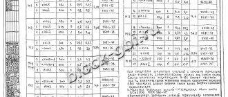
In residential buildings, the cross-sections of copper conductors must correspond to the calculated values, but not be less than those indicated in Table 7.1.1.
1 Until 2001, according to the existing construction backlog, the use of wires and cables with aluminum conductors was allowed.
Table 7.1.1. The smallest permissible cross-sections of cables and wires of electrical networks in residential buildings.
| Line names | Smallest cross-section of cables and wires with copper conductors, mm2 |
| Group network lines | 1,5 |
| Lines from floor to apartment panels and to the settlement meter | 2,5 |
| Distribution network lines (risers) for supplying apartments | 4 |
7.1.35. In residential buildings, laying vertical sections of the distribution network inside apartments is not allowed.
It is prohibited to lay wires and cables from the floor panel in a common pipe, common box or channel that supply lines to different apartments.
Fire-retardant installation in a common pipe, common box or channel of building structures made of non-combustible materials, wires and cables of apartment supply lines together with wires and cables of group lines of working lighting of staircases, floor-by-floor corridors and other indoor premises is allowed.
7.1.36. In all buildings, group network lines laid from group, floor and apartment switchboards to general lighting fixtures, plug sockets and stationary electrical receivers must be three-wire (phase - L, neutral working - N and neutral protective - PE conductors).
Combining zero working and zero protective conductors of different group lines is not allowed.
The neutral working and neutral protective conductors are not allowed to be connected on panels under a common contact terminal.
Conductor cross-sections must meet the requirements of clause 7.1.45.
7.1.37. Electrical wiring in the premises should be replaced: hidden - in the channels of building structures, embedded pipes; open - in electrical skirting boards, boxes, etc.
In technical floors, undergrounds, unheated basements, attics, ventilation chambers, damp and especially damp rooms, it is recommended that electrical wiring be carried out openly.
In buildings with building structures made of non-combustible materials, permanent, monolithic installation of group networks is allowed in the grooves of walls, partitions, ceilings, under plaster, in the floor preparation layer or in the voids of building structures, carried out with cable or insulated wires in a protective sheath. The use of permanently embedded wiring in panels of walls, partitions and ceilings, made during their manufacture at construction industry factories or carried out in the mounting joints of panels during the installation of buildings, is not allowed.
7.1.38. Electrical networks laid behind impenetrable suspended ceilings and in partitions are considered as hidden electrical wiring and should be installed: behind ceilings and in the voids of partitions made of flammable materials in metal pipes with localization capabilities and in closed boxes; behind ceilings and in partitions made of non-combustible materials 2 - in pipes and ducts made of non-flammable materials, as well as flame retardant cables. In this case, it must be possible to replace wires and cables.
2 Suspended ceilings made of non-combustible materials mean those ceilings that are made of non-combustible materials, while other building structures located above suspended ceilings, including interfloor ceilings, are also made of non-combustible materials.
7.1.39. In rooms for cooking and eating, with the exception of apartment kitchens, open laying of cables is allowed. Open wiring of wires in these rooms is not allowed.
In apartment kitchens, the same types of electrical wiring can be used as in living rooms and corridors.
7.1.40. In saunas, bathrooms, toilets, showers, as a rule, hidden electrical wiring should be used. Open cable routing is allowed.
In saunas, bathrooms, toilets, showers, laying wires with metal sheaths, in metal pipes and metal sleeves is not allowed.
In saunas for zones 3 and 4 according to GOST R 50571.12-96 “Electrical installations of buildings. Part 7. Requirements for special electrical installations. Section 703: Premises Containing Sauna Heaters" electrical wiring with an insulation temperature rating of 170oC must be used.
7.1.41. Electrical wiring in attics must be carried out in accordance with the requirements of Section. 2.
7.1.42. Through the basements and technical undergrounds of sections of the building, it is allowed to lay power cables with a voltage of up to 1 kV, supplying electrical receivers of other sections of the building. The specified cables are not considered as transit; laying transit cables through basements and technical undergrounds of buildings is prohibited.
7.1.43. Open laying of transit cables and wires through storerooms and warehouses is not permitted.
7.1.44. The lines supplying refrigeration units of trade and public catering enterprises must be laid from the ASU or main switchboard of these enterprises.
7.1.45. The selection of conductor cross-sections should be carried out in accordance with the requirements of the relevant chapters of the PUE.
Single-phase two- and three-wire lines, as well as three-phase four- and five-wire lines when supplying single-phase loads, must have a cross-section of zero working (N) conductors equal to the cross-section of phase conductors.
Three-phase four- and five-wire lines when supplying three-phase symmetrical loads must have a cross-section of zero working (N) conductors equal to the cross-section of phase conductors, if the phase conductors have a cross-section of up to 16 mm2 for copper and 25 mm2 for aluminum, and for large cross-sections - at least 50 % cross-section of phase conductors.
The cross-section of PEN conductors must be at least the cross-section of N conductors and at least 10 mm2 for copper and 16 mm2 for aluminum, regardless of the cross-section of the phase conductors.
The cross-section of PE conductors must be equal to the cross-section of phase conductors with a cross-section of the latter up to 16 mm2, 16 mm2 with a cross-section of phase conductors from 16 to 35 mm2 and 50% of the cross-section of phase conductors with larger cross-sections.
The cross-section of PE conductors not included in the cable must be at least 2.5 mm2 - in the presence of mechanical protection and 4 mm2 - in its absence.
Installation of a mounted electrical panel, fastening the panel, machines, wires
In this article, we will look at the step-by-step installation of a mounted electrical panel on site. Hello Dear Reader! After selecting the location for installation and completing the hanging switchboard, we proceed to its immediate installation. Let's take a step-by-step look at all the stages of installing a hinged panel and start with preparing the tool.
Tool for installing electrical panels
To install the shield you will need the following tool:
- Electric impact drill or hammer drill;
- A set of drills according to the type of wall on which the electrical panel will be installed;
- Building level;
- Yardstick;
- Screwdriver Set;
- Pliers;
- Wire cutters;
- Knife or special tool for stripping wire insulation;
- Tags for marking wires;
- Insulating tape;
- Pencil.
After preparing the tool and the electrical panel housing, you can begin installing it.
Marking the location for installing a wall-mounted electrical panel
The electrical panel should be installed strictly vertically or horizontally, as you prefer. It is better to choose 1.5-1.7 meters for the installation height of the electrical panel for ease of further maintenance.
Before starting work, the electrical panel housing must be disassembled into its component parts.
On the body of the electrical panel there are technological perforated holes for entering electrical cables into the electrical panel. There are usually more of them than needed.
It is necessary to select the proposed places for the cables to enter the shield and break out the technological holes.
Note: A mounted electrical panel can be installed both before and after electrical installation. Depending on the type of electrical wiring, electrical cables are inserted into the panel from above and/or from below, through the side walls, or through the rear wall of the electrical panel.
Steps for installing a wall-mounted electrical panel
1. Measure the installation height of the electrical panel from the floor and draw a horizontal line along the building level;
2. Draw a vertical line along the planned edge of the electrical panel installation;
3. Attach the base of the electrical panel body to the marks made and mark the places for fastening with a pencil. On the base of the case there are special technological holes for attaching the electrical panel. There are two, four or six mounting holes, depending on the size of the electrical panel.
Note: If you are installing an electrical panel on a wall made of plasterboard, then when purchasing a wall-mounted electrical panel, choose a model that can be equipped with special fasteners for installation on a plasterboard wall (see photo).
4.Load the drill bit into the drill and drill holes in the wall to mount the electrical panel;
5.Install the dowels into the drilled holes. Place the base of the electrical panel housing against the wall and screw it to the wall.
Note: Do not forget to insert the electrical wiring cables into the switchboard, which are inserted into the switchboard through the rear wall.
Before final tightening of the mounting screws, accurately set the installation level of the electrical panel. Use a building level for this. Check the installation level of the electrical panel horizontally and vertically, and finally tighten the mounting screws.
The base of the electrical panel housing is installed.
We begin assembling the electrical panel
6. To begin, install DIN rails (3) and terminal blocks (1,2) in the electrical panel.
For their installation, special fastenings are made at the base of the electrical panel. The mounting locations depend on the manufacturer of the electrical panel. Typically, connecting blocks are attached at the top or bottom of the shield.
DIN rails are attached across the shield in the center, in one, two, three or four rows. Accordingly, shields are called single-row, double-row, three-row and four-row.
Left a little.
7. You need to bring all the wires and electrical cables into the electrical panel. First lay out the electrical cables along the electrical panel body on the right and left.
If there are a large number of wires, lay them out under the DIN rails.
Internal electrical equipment
7.1.46. In food preparation rooms, except for apartment kitchens, lamps with incandescent lamps installed above workplaces (stoves, tables, etc.) must have protective glass underneath. Lamps with fluorescent lamps must have grilles or grids or lamp holders that prevent the lamps from falling out.
7.1.47. In bathrooms, showers and lavatories, only electrical equipment should be used that is specifically designed for installation in the relevant areas of these premises in accordance with GOST R 50571.11-96 “Electrical installations of buildings. Part 7. Requirements for special electrical installations. Section 701 - Bathrooms and Shower Facilities" and the following requirements must be met:
- — electrical equipment must have a degree of protection against water not lower than: in zone 0 — IPx7;
- in zone 1 - IPx5;
- in zone 2 - IPx4 (IPx5 - in public baths);
- in zone 3 - IPx1 (IPx5 - in public baths);
- — in zone 1 only water heaters can be installed;
7.1.48. Installation of plug sockets in bathrooms, showers, soap rooms of baths, rooms containing heaters for saunas (hereinafter referred to as “saunas”), as well as in washing rooms of laundries is not allowed, with the exception of bathrooms in apartments and hotel rooms.
In the bathrooms of apartments and hotel rooms, it is allowed to install plug sockets in zone 3 in accordance with GOST R 50571.11-96, connected to the network through isolation transformers or protected by a residual current device that responds to a differential current not exceeding 30 mA.
Any switches and sockets must be located at a distance of at least 0.6 m from the doorway of the shower stall.
7.1.49. In buildings with a three-wire network (see clause 7.1.36.), plug sockets with a current of at least 10 A with a protective contact must be installed.
Plug sockets installed in apartments, living rooms in dormitories, as well as in rooms for children in child care institutions (kindergartens, nurseries, schools, etc.) must have a protective device that automatically closes the sockets of the socket when the plug is removed.
7.1.50. The minimum distance from switches, sockets and electrical installation elements to gas pipelines must be at least 0.5 m.
7.1.51. It is recommended to install switches on the wall on the side of the door handle at a height of up to 1 m; they can be installed under the ceiling with control using a cord.
In rooms for children in children's institutions (kindergartens, nurseries, schools, etc.), switches should be installed at a height of 1.8 m from the floor.
7.1.52. In saunas, bathrooms, toilets, soap rooms, steam rooms, washing rooms, laundries, etc. installation of switchgear and control devices is not permitted.
In washbasin rooms and zones 1 and 2 (GOST R 50571.11-96) of bathrooms and shower rooms, it is allowed to install switches operated by a cord.
7.1.53. Switching devices for lighting networks in attics that have building structure elements (roofing, trusses, rafters, beams, etc.) made of flammable materials must be installed outside the attic.
7.1.54. Switches for work lamps, safety and evacuation lighting of premises intended for the presence of a large number of people (for example, retail premises of shops, canteens, hotel lobbies, etc.) must be accessible only to service personnel.
7.1.55. A lamp should be installed above each entrance to the building.
7.1.56. House license plates and fire hydrant signs installed on exterior walls of buildings must be illuminated. Electric light sources for license plates and hydrant indicators must be powered from the internal lighting network of the building, and fire hydrant indicators installed on external lighting poles must be powered from the external lighting network.
7.1.57. Fire safety devices and security alarms, regardless of the category of reliability of the building's power supply, must be powered from two inputs, and in their absence, by two lines from one input. Switching from one line to another should be automatic.
7.1.58. Electric motors, distribution points, separately installed switching devices and protective devices installed in the attic must have a degree of protection of at least IP44.
Where should the RCD be installed?
To determine where to install the residual current device, you need to remember the speed of current flow through the wires. It is equal to the speed of light - 300 thousand km/sec. In a standard C 16 machine, the turn-on time when passing currents of 5×In (80 A) will be 0.02 seconds. The distance it will cover is 6000 km.
In the event of a short circuit, the current will completely pass through the coupling device - RCD - cable - socket. In this case, the switch does not operate instantly, as a result of which the insulation melts and the socket contacts burn out.
The RCD does not fail, since a short circuit is an inertial reaction. A time of 0.02 seconds is simply not enough to melt the insulating coating and damage the parts. Even taking into account the breaking capacity, the protective devices will work properly regardless of the installation location:
Protective devices will work properly regardless of the installation location
- Automatic - RCD. The phase is supplied using a jumper, and the zero is supplied directly to the protective device. The wire for the sockets is connected to the device and the PE bus.
- RCD - automatic. The wire is connected to the sockets through different paths. The phase one goes to the machine, the zero goes to the protection device or the zero bus.
Thus, there is no difference where the RCD was installed - before or after the automatic device.
Electricity metering
7.1.59. In residential buildings, one single- or three-phase billing meter (with three-phase input) should be installed for each apartment.
7.1.60. Calculation meters in public buildings that house several electricity consumers must be provided for each consumer, isolated in administrative and economic terms (studio, shops, workshops, warehouses, housing maintenance offices, etc.).
7.1.61. In public buildings, estimated electricity meters must be installed on the ASU (main switchboard) at the points of balance demarcation with the energy supply organization. If there are built-in or attached transformer substations, the power of which is fully used by consumers of a given building, the calculated meters should be installed at the low-voltage terminals of power transformers on combined low-voltage switchboards, which are also the building’s ASU.
ASU and metering devices for different subscribers located in the same building may be installed in one common room. By agreement with the energy supplying organization, settlement meters can be installed at one of the consumers, from which the ASU supplies other consumers located in the building. At the same time, control meters should be installed at the inputs of the supply lines in the premises of these other consumers for settlements with the main subscriber.
7.1.62. Estimated meters for the general house load of residential buildings (lighting of staircases, building management offices, yard lighting, etc.) are recommended to be installed in ASU cabinets or on main switchboard panels.
7.1.63. It is recommended to place residential meters together with protection devices (circuit breakers, fuses).
When installing apartment panels in the hallways of apartments, meters, as a rule, should be installed on these panels; installation of meters on floor panels is allowed.
7.1.64. To safely replace a meter directly connected to the network, a switching device must be provided in front of each meter to remove voltage from all phases connected to the meter.
Disconnecting devices for removing voltage from settlement meters located in apartments must be located outside the apartment.
7.1.65. After the meter connected directly to the network, a protection device must be installed. If several lines equipped with protection devices extend after the meter, installation of a common protection device is not required.
7.1.66. It is recommended to equip residential buildings with remote meter reading systems.
Why is it unacceptable to install a circuit breaker on the neutral wire?
I corresponded via email with Volodymirom about the inadmissibility of installing a circuit breaker on the neutral wire of the electrical wiring. For those who want to understand the intricacies of this issue, I think its result will be useful.
Volodymyr: I’m currently making an electrical panel in the apartment and a question has arisen. Why can’t separate machines be set to zero and phase, but only paired ones? Why “It is strictly prohibited to install a single circuit breaker on the neutral wire.”?
Answer: When installing separate circuit breakers on the neutral and phase wires, designed for the same protection current, in the event of an overload of the electrical wiring, only one of them is likely to work. This is due to the fact that circuit breakers have a variation in the magnitude of the operating current.
If the machine installed on the neutral wire is triggered, then all electrical wiring, including the neutral wire, will be under phase voltage. The phase will reach the neutral wire through electrical appliances that are turned on at this time, for example, a TV in standby mode, a refrigerator. And if a person thinks that since the machine has worked, it means that the wires are de-energized and, therefore, safe, then he can start repairing the electrical wiring and accidentally come under dangerous voltage.
That's why it's impossible. It is possible to install twin circuit breakers in household electrical wiring, but there is no point in this, only extra costs, since a paired circuit breaker costs much more. Therefore, the neutral wire is laid directly, and a machine must be installed on the phase wire.
Volodymyr: If during a short circuit the zero-machine is knocked out faster, and the phase-man-earth short circuit continues, then the phase-machine will still be knocked out. Also, both can work approximately simultaneously. That is, the machine must be set to zero more powerful than the phase one. But there will be no disruptions to the network, only additional costs.
You can, of course, install a machine designed for a higher current on the neutral wire, but where is the guarantee that the machine will not fail? After all, the main value for any person is his health and life! Therefore, even with the hypothetical possibility of causing harm to a person, they do everything to exclude it.
Volodymyr: I’m just starting to master electrical installation in practice, including using your recommendations. And I want to understand the technical side in order to better understand the recommendations of the PUE. So forgive me if I'm wrong somewhere.
There are two common situations: 1. Short circuit phase-man-earth or phase-earth. A phase machine will work here. Zero machine has nothing to do with it.2. Short circuit phase-man-zero or phase-zero. A phase machine and/or a zero machine will work here. That is, if the phase machine does not work, then the zero one will break the circuit.
Answer: Your reasoning is based on the assumption that the machine serves to protect a person from electric shock. But the machine is designed solely to protect electrical wiring from destruction if the current flowing through it exceeds the permissible limit. To protect people, an RCD is installed.
Let me give you an example: a man decided to replace a light bulb in a chandelier and turned off only the switch, and not the machine, this is usually what they do. The wiring in the chandelier was old, and the neutral wire was touching the metal body of the chandelier. The man stood on the ground and, screwing in the light bulb, held the chandelier by the metal body with one hand.
At this time, another family member decided to turn on an electrical appliance, whose insulation at the exit from the plug had frayed and the wires were short-circuited. A short circuit occurred, and only the circuit breaker installed on the neutral wire worked, and a phase appeared on the neutral wire of the entire apartment wiring. As a result, a person changing a light bulb can receive an even fatal electric shock. The machine can also work when the lights are turned on if the light bulb burns out at that moment.
PUEs are written based on accidents involving electric shock to people and it is impossible to describe all situations in which people were injured or died. You just need to follow the PUE and then the electrical wiring will never fail.
For a private house 380 v 15 kW
To calculate the input circuit breaker for a private home, it is necessary to take into account the following values: network voltage (U), power (P) of all electrical appliances that will operate in the network, a correction factor that takes into account the simultaneous inclusion of electrical appliances and the quality of the electrical wiring.
Calculation example:
Let us assume that the sum of the powers of all electrical appliances in a residential building is 15 kW (the same power in Russia is usually supplied to private residential buildings) at a voltage of 380 V. To calculate the current, we use Ohm’s Law for an electrical circuit:
I=P/U;
I=15000/380 = 39.47 A.
We introduce a correction factor. Since all electrical appliances in the house will not turn on at the same time and, taking into account the old electrical wiring, we accept the value of the correction factor equal to 0.85.
https://www.youtube.com/watch?v=7sz6sf-gUPg
In=39.47x0.85 = 33.55.
The closest nominal values of the machines are: 32 A and 40 A. We choose the denomination in the smallest direction. And we find that for our private house we need a three-pole or four-pole 32 A input circuit breaker.
Why combine a switch with a “machine”
At the household level, this ensures the convenience of managing the electrical network and the durability of the home electrical network, but the decision still depends on you. Do you plan to de-energize the line a few times a year, for example, only when carrying out emergency repairs? Then you can get by with the “automatic” lever.
If we are talking about the electrical network of an apartment building or an industrial building, which have increased safety requirements. First of all, place a switch at critical places on the input cable. It will work as a switching device, with the help of which the line is de-energized with one movement. Moreover, the device must have a visible circuit break, without protective covers.
For example, the P2M model from Elecon for 250A or the PE19 series disconnector from IEK in which, when the network is disconnected using a lever, a break in the contacts is visually noticeable - there are no covers or panels obscuring the insides of the structure. For what? So that when maintaining the network at the site, the person carrying out the work is 100% sure that the system is de-energized. But the design of the “machine gun” cannot provide this visual clarity, because the device body is closed.
The use of switches is advisable in industries where personnel must de-energize equipment at the end of the working day or before carrying out repair work. Or, for example, to turn on and off the perimeter lighting system.
Neutral mode for selecting an input machine
For various neutral modes, the following input machines are used
Selecting an input machine for the TN-S system:
The input machine for the TN-S system must be
- Single-pole with zero or double-pole,
- Three-pole with neutral or four-pole.
This is necessary to simultaneously disconnect the apartment’s electrical network from the neutral working and phase conductors on the power input side. since the neutral and protective conductors are separated throughout.
Selecting an input machine for the TN-C system:
For the TN-C power system, the input circuit breaker is installed single-pole (for a power supply of 220 V) or three-pole (for a power supply of 380 V). They are installed on phase working conductors.