In this article we will talk about the methods and rules for calculating ventilation in rooms. Ventilation systems are complex engineering networks. High-quality air exchange is the result of precise mathematical calculations , where there is no room for errors. What are the dangers of design violations? Insufficient or excessive air circulation. In the first case, this causes stagnation and stuffiness in the room. In the second - drafts, loss of heat and, as a result, colds. For industrial and commercial facilities, the consequences are much more serious: from regulatory fines to production shutdowns.
How to calculate ventilation coefficient
In rooms where people are the main source of changes in air condition, the minimum ventilation coefficient can be calculated using the following formula :
VN = n • Vj
- where VN is the supply air flow rate in m³/h;
- n is the number of people in the room;
- Vj — minimum inflow per person per hour, m³/h.
The minimum volume of supply air is specified in SNiP 13330.2012, 41-01-2003, 2.08.01-89 and depends on the characteristics of the room:
- ventilated room - 30 m³/h;
- room with air conditioning or ventilation with non-opening windows - 60 m³/h.
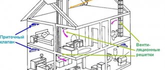
The organization of air exchange in a room comes down to the correct distribution of supply and exhaust elements in relation to the area where people stay and sources of pollution. The design of supply ducts has a decisive influence on the distribution and organization of air exchange, since their range is much greater than that of exhaust elements.
How to calculate supply and exhaust ventilation
In order for the ventilation system to work effectively, it is necessary to provide a sufficient amount of supply air, adapted to the type of room and the number of people in it. An inflow that is too small will not provide adequate air exchange, and one that is too high will lead to oversizing of the installation and additional costs. How to calculate supply and exhaust ventilation for a room? Below are the main methods.
Methods for calculating air exchange rates:
- By area: S×3 m³/h , where S is the size of the room for which the ventilation system is calculated, 3 m³/h is a constant value indicated in regulatory documents as recommended.
- According to sanitary standards: 60 m³/h×A + 20 m³/h×B, where A is the number of permanent residents, B is the number of temporarily present.
- By multiples: L=N×V , where N is the coefficient from the SNiP table, and V is the volume of the room.
The methodology for calculating ventilation is strictly regulated. The initial data is specified in SNiP, GOST and SP. Previously, we talked about what supply and exhaust ventilation is.
How to calculate exhaust ventilation in production
An effective industrial ventilation unit effectively removes contaminated air from the point of emission, limiting its spread in the hall as much as possible, and at the same time provides the supply of purified and treated air for the needs of employees. It is necessary to think through and plan the operation of local exhaust, general exchange and supply ventilation units. Calculation of the required air flow of extracted and supplied air is the beginning of work on the ventilation project for production workshops. The key issue is the correct location of air intakes and outlets in the room and the choice of equipment (fans, air handling units, ventilation devices, pipes, dust collectors, filters).
Ventilation design must meet the requirements set out in the relevant codes and standards. Accurate knowledge of the technological processes of distribution of pollution sources, their type, quantity and method of distribution is necessary. Each production plant project is unique and requires individual analysis. Employees of the QWENT engineering company will professionally install industrial ventilation in production.
How to calculate ventilation in a house
The performance of the ventilation network in a private home is calculated in two ways.
- The first is in terms of room volume and circulation rates.
- The second is based on the number of people constantly present in the building and the air flow rate per person.
For residential premises, the norm is a single air exchange. To calculate it using the first method, you need to multiply the volume of the room by the replacement rate of air masses.
The air flow rate for a person who is constantly in the room is 60 m3/h, and if a person is in it temporarily - 20 m3/h. This data will be needed for the second method. The number of people in the room must be multiplied by the air flow rate.
The air exchange rate is a number that shows how many times per hour the air in the room is completely replaced with fresh air. The multiplicity is regulated by standards and depends on the room. It is determined using tables.
For a private house, you can take the average value between the results calculated using these two methods.
Sports and recreational institutions
When exercising in a gym, the rate of air exchange plays an important role, since during physical activity it is necessary to ensure the flow of fresh oxygen into the lungs of each visitor, taking into account the fairly large volumes of the hall. Thus, the requirements stipulate the need to ensure that 80 m3/h of air enters the gym when there are visitors.
The calculation of the air exchange rate for a swimming pool is based on the number of people in it and should be 20 m³/h per 1 person. At the same time, taking into account the specifics of being in a sauna or bathhouse, it is necessary to ensure a change of 10 m³ of air every hour. At the same time, taking into account the large volumes of saturated steam produced, it is possible to calculate air exchange based on moisture emissions.
How to calculate natural ventilation in a room
Natural ventilation works without mechanical stimulation. Air changeability is ensured by gravity - the temperature difference between incoming and exhaust air. For normal operation, it is necessary to calculate the height of the vertical exhaust shaft. Calculations are carried out using the selection method, because vertical shafts in most cases have a standard size and height. The height of the shaft is substituted into the calculation of natural ventilation, carried out according to the formula: p=h(pH-pB) , where p is the gravitational pressure in the channel, h is the height of the air duct, pH is the density of incoming air masses, pB is the density of exhaust air.
Gravity ventilation involves designing places for air supply to the premises of a building and places for exhaust air removal. In this case, air enters the room through window and sill openings, leaky connections and as a result of periodic opening of windows and doors. The disadvantage of natural ventilation is its dependence on the outside air temperature. The efficiency of exchange decreases with increasing outdoor temperature. The higher the outside air temperature, the smaller the pressure difference causing air flow, so with constant resistance to flow, air exchange worsens. However, in winter, cold air enters the premises uncontrollably, which requires additional thermoregulation.
Selecting the height of the pipes
The next step is to determine the traction force that occurs inside the exhaust unit at a given height difference. The parameter is called available gravitational pressure and is expressed in Pascals (Pa). Calculation formula:
- p – gravitational pressure in the channel, Pa;
- H – height difference between the outlet of the ventilation grille and the cut of the ventilation duct above the roof, m;
- ρair – room air density, take 1.2 kg/m³ at home temperature +20 °C.
The calculation method is based on selecting the required height. First, decide how much you are willing to raise the exhaust pipes above the roof without damaging the appearance of the building, then substitute the height value into the formula.
Example. We take a height difference of 4 m and get the thrust pressure p = 9.81 x 4 (1.27 - 1.2) = 2.75 Pa.
Now comes the most difficult stage - the aerodynamic calculation of the outlet channels. The task is to find out the resistance of the air duct to the flow of gases and compare the result with the available pressure (2.75 Pa). If the pressure loss is greater, the pipe will have to be expanded or the bore diameter increased.
The aerodynamic resistance of the air duct is calculated by the formula:
- Δp – total pressure loss in the shaft;
- R – specific frictional resistance of the passing flow, Pa/m;
- H – channel height, m;
- ∑ξ – sum of local resistance coefficients;
- Pv – dynamic pressure, Pa.
Let us show with an example how the resistance value is calculated:
- We find the value of dynamic pressure using the formula Pv = 1.2 x 1² / 2 = 0.6 Pa.
- We find the friction resistance R from the table, focusing on the dynamic pressure of 0.6 Pa, flow velocity of 1 m/s and air duct diameter of 225 mm. R = 0.078 Pa/m (indicated by a green circle).
- The local resistances of the exhaust shaft are a louvered grille, a 90° upward outlet and an umbrella at the end of the pipe. The coefficients ξ of these parts are constant values, equal to 1.2, 0.4 and 1.3, respectively. Sum ξ = 1.2 + 0.4 + 1.3 = 2.9.
- Final calculation: Δp = 0.078 Pa/m x 4 m + 2.9 x 0.6 Pa = 2.05 Pa.
Let's compare the calculated pressure generated in the air duct and the resulting resistance. The traction force p = 2.75 Pa is greater than the pressure loss (resistance) Δp = 2.05 Pa, a 4-meter-high shaft is too high, it makes no sense to build one.
Now let’s shorten the ventilation duct to 3 m and recalculate again:
- Available pressure p = 9.81 x 3 (1.27 - 1.2) = 2.06 Pa.
- The resistivity R and local coefficients ξ remain the same.
- Δp = 0.078 Pa/m x 3 m + 2.9 x 0.6 Pa = 1.97 Pa.
The natural draft pressure of 2.06 Pa exceeds the system resistance Δp = 1.97 Pa, which means that a three-meter-high shaft will work properly for natural exhaust and will provide the required flow of removed gases.
Important note. The difference between the traction force and the resistance of the air duct was only 2.06 - 1.97 = 0.09 Pa. In order for the hood to work stably in any weather, it is better to take the height of the pipe in our example with a margin of 3.5 m.
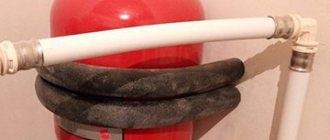
The ventilation channel Ø225 mm can be divided into 2 smaller pipes, but not by diameter, but by cross-section. We get 2 round ventilation ducts 150-160 mm, as shown in the photo. The height of both shafts remains unchanged - 3.5 m.
How to calculate ventilation in an apartment
- Children's room, bedroom, living room - air exchange once per hour.
- Kitchen with electric stove - 60 m³/h.
- Kitchen with gas stove - air exchange once per hour + 100 m³/h when the stove is running.
- Bathroom - 25 m³/h.
- Library, recreation area - 0.5 times per hour.
- Wardrobe, hallway, utility room - 0.2 times per hour.
The calculation of ventilation in a residential area is carried out on the basis of SNiP 13330.2012, 41-01-2003, 2.08.01-89. Most often, two methods are used: by volume of air flow per hour or hourly frequency. The standards depend on the type of premises listed above.
Bottom line
Knowing the air balance of a residential building, the size of the cross-section of the air ducts is selected. Most often, rectangular channels with an aspect ratio of 3:1 or round are used.
Home ventilation plan Source sustaintrust.org.nz
To conveniently calculate the cross-section, you can use an online calculator or a diagram that takes into account the speed and air flow.
For natural ventilation, the speed in the main and branch air ducts is assumed to be 1 m/h. In the forced system, 5 and 3 m/h, respectively.
With a required air exchange of 200 m3/h, it is sufficient to implement a natural ventilation system. For large volumes of transported air, mixed recirculation is used. Devices designed for performance are installed in the channels, which will provide the necessary microclimate parameters.
How to calculate forced ventilation
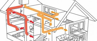
Forced ventilation works on a mechanical principle. Electric fans are responsible for air movement and circulation. There are 3 types of mechanical ventilation. The supply air supply brings air into the room, and the exhaust air supply removes it. The supply and exhaust system works for supply and outflow at the same time. It can be equipped with a recuperator - a heat exchanger that absorbs the heat of the exhaust air and warms the supply air.
When making calculations and designing, the following are taken into account:
- volume of inflow and outflow;
- dimensions of the mines;
- air duct parameters;
- power of electric fans;
- heat loss during the heating period;
- heat exchanger characteristics;
- resource of filtration systems;
- parameters of duct heaters and coolers;
- consumed electricity;
- sound insulation thickness.
independently calculate mechanical ventilation . It's better to leave this to an engineer.
Selecting an air handling unit
To select an air handling unit, we will need the values of three parameters: overall performance, heater power and air network resistance. We have already calculated the performance and power of the heater.
To select a suitable model, we need to select ventilation units whose maximum performance is slightly greater than the calculated value. After this, using the ventilation characteristic, we determine the system performance at a given network resistance. If the obtained value is slightly higher than the required performance of the ventilation system, then the selected model is suitable for us.
As an example, let’s check whether a ventilation unit with the ventilation characteristics shown in the figure is suitable for a cottage with an area of 200 m².
The estimated productivity is 450 m³/h. Let us take the network resistance to be 120 Pa. To determine the actual performance, we must draw a horizontal line from the value of 120 Pa, and then draw a vertical line down from the point of its intersection with the graph. The intersection point of this line with the “Performance” axis will give us the desired value - about 480 m³/h, which is slightly more than the calculated value. So this model suits us.
Note that many modern fans have flat ventilation characteristics. This means that possible errors in determining the network resistance have almost no effect on the actual performance of the ventilation system. If in our example we had made a mistake in determining the resistance of the air supply network by 50 Pa (that is, the actual network resistance would not have been 120, but 180 Pa), the system performance would have dropped by only 20 m³/h to 460 m³/h, which had no effect would be the result of our choice.
After choosing an air handling unit (or a fan, if a dial system is used), it may turn out that its actual performance is noticeably higher than the calculated one, and the previous model of the air handling unit is not suitable because its performance is not enough. In this case we have several options:
- Leave everything as is, but the actual ventilation performance will be higher than the calculated one. This will lead to increased energy consumption spent on heating the air during the cold season.
- “Strangle” the ventilation unit using balancing throttle valves, closing them until the air flow in each room drops to the calculated level. This will also lead to excessive energy consumption (although not as much as in the first option), since the fan will work with excess load, overcoming the increased network resistance.
- Do not turn on maximum speed. This will help if the ventilation unit has 5–8 fan speeds (or smooth speed control). However, most budget ventilation units have only 3-step speed control, which most likely will not allow you to accurately select the desired performance.
- Reduce the maximum productivity of the air handling unit exactly to a specified level. This is possible if the automatic ventilation unit allows you to adjust the maximum fan rotation speed.
How to calculate air ducts for ventilation
To calculate the cross-sectional area of air ducts, you need to know the volume of air entering the room per unit time and the speed of movement of air masses in the ventilation duct. After calculating the volume, the parameters of the exhaust ducts are calculated. To find out the cross-sectional area, use the formula: F = L/3600 x Vс , where L is the specific flow rate of exhaust ventilation, m³/h; Vc – speed of air movement in the line, m/s. Previously, we talked in detail about air ducts for ventilation.
Calculate the diameters of ventilation ducts
Further calculations are somewhat more complicated, so we will provide each step with examples of calculations. The result will be the diameter and height of the ventilation shafts of our one-story building.
We distributed the entire volume of exhaust air into 3 channels: 100 cubic meters. The hood in the kitchen is forcibly removed when the stove is turned on, the remaining 271 cubic meters goes through two identical shafts naturally. The flow rate through 1 air duct will be 271 / 2 = 135.5 m³/h. The cross-sectional area of the pipe is determined by the formula:
- F – cross-sectional area of the ventilation duct, m²;
- L – exhaust flow through the shaft, m³/h;
- ʋ—flow speed, m/s.
Reference. The air speed in the natural ventilation channels is in the range of 0.5–1.5 m/s. We take the average value as the calculated value - 1 m/s.
How to calculate the cross-section and diameter of one pipe in the example:
- We find the diameter size in square meters F = 135.5 / 3600 x 1 = 0.0378 m².
- From the school formula for the area of a circle, we determine the diameter of the duct D = 0.22 m. We select the nearest larger air duct from the standard range - Ø225 mm.
- If we are talking about a brick shaft embedded inside the wall, then the size of the ventilation duct 140 x 270 mm will fit the found cross-section (good coincidence, F = 0.0378 sq. m.).
Brick shafts have strictly fixed dimensions - 14 x 14 and 27 x 14 cm.
The diameter of the outlet pipe for a household hood is calculated in the same way, only the flow speed forced by the fan is assumed to be greater - 3 m/s. F = 100 / 3600 x 3 = 0.009 m² or Ø110 mm.
How to calculate the cost of ventilation
The total cost of a ventilation system consists of several elements. The most important of them are:
- project cost;
- equipment and installation costs;
- operating costs (control panel energy consumption, filter replacement, maintenance).
The price of equipment depends on the quality of workmanship, power, technical parameters, additional functions (for example, cooling or humidifying the air in the house), convenient control (degree of automation). The complexity of installation also increases the cost. Our website contains the most detailed price list for designing a ventilation system with prices per m².
Design errors
At the project creation stage, errors and shortcomings are often encountered. This may be excessive background noise, reverse or insufficient draft, blowing (upper floors of multi-storey residential buildings) and other problems. Some of them can be solved after installation is completed, using additional installations.
A striking example of low-skilled calculation is insufficient exhaust draft from a production facility without particularly harmful emissions. Let's say the ventilation duct ends in a round shaft, rising 2,000 - 2,500 mm above the roof. Raising it higher is not always possible or advisable, and in such cases the principle of flare emission is used. A tip with a smaller diameter of the working hole is installed in the upper part of the round ventilation shaft. An artificial narrowing of the cross-section is created, which affects the rate of gas release into the atmosphere - it increases many times over.
Sample Project
The method for calculating ventilation allows you to obtain a high-quality internal environment by correctly assessing the negative factors that worsen it. We employ professional designers of engineering systems of any complexity. We provide services in Moscow and neighboring regions. The company also successfully engages in remote collaboration. All communication methods are listed on the “Contacts” page, please contact us.
Calculation according to sanitary and hygienic standards
Air exchange in the room is regulated by SNiP, according to which the ventilation system must ensure:
- Supplying outdoor air to living rooms such as living room, bedrooms, offices, children's rooms and kitchen with an external window.
- Removing exhaust air from the kitchen, bathroom, toilet, corridor, rooms without windows. These include: dressing room, pantry, utility room.
The calculation of the amount of ventilated air is based on the balance of heat, moisture and pollutant emissions, that is, factors causing changes in air parameters in the room. The amount of supply air can be calculated based on:
- heat load of the room (heat gain);
- steam gain;
- the amount of gaseous pollutants emitted into the premises;
- number of people.
The choice of method of supplying air to a room requires careful analysis from the point of view of ensuring adequate comfort for the users in it. Determining the cooling capacity of the air flow and comparing it with acceptable values is a prerequisite for correct air distribution. The method of supplying air to the room determines the permissible inlet temperature, which determines the amount of air flow, the size of air ducts and other ventilation devices.
Stages
The selection of the optimal air exchange system in terms of power and cost is carried out step by step. The design order is very important, since the efficiency of the final product depends on its observance:
- Determination of the type of ventilation system. The designer analyzes the source data. If you need to ventilate a small living space, then the choice falls on a supply and exhaust system with natural impulse. This will be enough when the air flow is small and there are no harmful impurities. If you need to calculate a large ventilation complex for a factory or public building, then preference is given to mechanical ventilation with the function of heating/cooling the inlet, and if necessary, then with calculations based on hazards.
- Outlier analysis. This includes: thermal energy from lighting fixtures and machines; fumes from machines; emissions (gases, chemicals, heavy metals).
- Calculation of air exchange. The task of ventilation systems is to remove excess heat, moisture, and impurities from the room with an equilibrium or slightly different supply of fresh air. To do this, the air exchange rate is determined, according to which the equipment is selected.
- Equipment selection. Produced according to the obtained parameters: required volume of air for supply/exhaust; indoor temperature and humidity; the presence of harmful emissions, ventilation units or ready-made multi-complexes are selected. The most important parameter is the volume of air required to maintain the design expansion ratio. Filters, heaters, recuperators, air conditioners and hydraulic pumps are used as additional network devices that ensure air quality.
Calculation of the ventilation system by multiplicity
Multiplicity standards suggest taking into account the type of room. The multiplicity shows how many times all the air in the room should be changed in an hour. When determining the air exchange rate for each specific room, designers take into account the regulatory indicators recorded in sanitary and hygienic standards, GOSTs and building rules, for example SNiP 2.08.01-89.
The amount of air can be calculated using the formula L=N*V , where N is the air exchange rate per hour, taken from the table; V – volume of the room, cubic meters. m.
Heater power
A heater or duct heater is a universal device for heating supply air, installed in ventilation ducts. Heater power (Q) is calculated by the formula: Q = V • ρ • cp • ΔT [kW] , where V is the volumetric air flow [m³/s], ρ is the air density [1.2 kg/m³], cp is the specific heat capacity of air [1.005 kJ/(kg • K); ΔT is the difference in air temperatures before and after the heater [°C]. Manufacturers of air heaters also provide nomograms, according to which equipment can be selected much faster. It is enough to know the volume of the room, the difference between the supply air temperature and the heating temperature. Previously, we talked about what a heater in ventilation is.
Ventilation calculation example
- reception: 2*60 = 120 m³/h;
- workroom No. 1: 4*60+2*20 = 280 m³/h;
- No. 2: 6*60+2*20 = 400 m³/h;
- No. 3: 8*60+2*20 = 520 m³/h.
Above is an example of calculating the inflow volume.
For clarity, we will calculate the parameters of the ventilation network of a classic medium-sized office. Input data: reception (two workplaces), 3 offices (4, 6 and 8 workplaces + two places for visitors in each). Each employee's workplace requires 60 m³ of fresh air per hour. Additional - 20 m³/h.
The total supply air flow will be 120+280+400+520 = 1320 m³/h.
Health care institutions
The air exchange rate in institutions belonging to the healthcare system has the highest values for wards in which inpatient treatment of patients with detected pathologies of infectious (160 m³/h) and non-infectious (80 m³/h) origin is carried out.
According to the standards, most other premises, including doctors’ offices and treatment rooms, must have an exhaust ratio with a natural type of air exchange organization equal to 1-2 units/hour.
A separate point worth mentioning is the organization of the ventilation system for operating rooms. According to modern requirements, they must use a 3-fold air purification system, while operating devices must provide a minimum flow of 1200 m³ of air per hour.