The plan of the strip foundation reflects not only the axial drawing of the base of the structure, but also the list of necessary materials. It also indicates the geometric characteristics of the structure in relation to the existing land plot and the contour of the area.
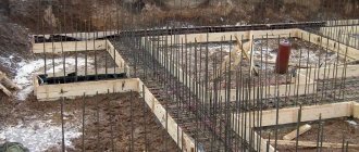
General view of the foundation strip Source st-par.ru
Everything you need to know about strip foundations.
Experts in the construction industry classify the strip type of base as a monolithic base, but only with the exception of one, but very significant difference - cost-effectiveness and accessibility. Despite the fact that the amount of concrete solution required for the work is reduced, the foundation does not lose its strength characteristics and is particularly reliable. Today it is used for the construction of high-rise buildings, industrial and public facilities, and also, of course, in the construction of country cottages of any number of floors.
Monolithic foundation plan drawing.
Features of drawing up house projects: drawings and plans as the main part of planning
Having decided on the layout of the house, you need to mentally imagine the life of the family in the building, think through all the elements so as not to miss anything. Therefore, there is no need to rush into creating the final layout of the house. The finished drawings and plans of the house must be as perfect as possible so that the final result satisfies all household members, and the constructed home lasts for the maximum number of years without reconstruction or alterations. The final version of the sketch should be discussed at a family council, taking into account all the details, down to the smallest detail.
First of all, the desired number of floors is indicated in the house plan. It can be a spacious one-story house, a compact two-story cottage, or a luxurious two-story mansion with an attic.
The internal layout shown on building drawings should include the following areas:
- living rooms;
- utility rooms;
- common areas;
- additional extensions.
A one-story house is divided into zones using partitions, as well as placing rooms of the same functionality in one wing. In two-story cottages, bedrooms, guest and children's rooms are traditionally located on the second floor, and on the first there are utility and service premises for common use.
Supports for strip base.
Support structures that are used for this type of foundation come in 2 varieties, namely:
- Strip monolithic foundation. The concrete mixture is gradually and evenly poured into the pit;
- Prefabricated strip foundation. In addition to the mortar, ready-made reinforced concrete structures are also used.
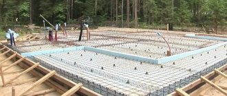
Prefabricated strip foundation plan drawing.
Drawing with additional drawings (large scale).
In order to determine how deep the trench should be in this case, it is necessary to be guided by a soil freezing map. It is different for each area, and if an inaccurate indicator is used during work, then such an oversight can be fraught with shrinkage of the structure or even destruction of the entire foundation. The width of the pit depends on the load that will be placed on the foundation during the direct operation of the house.
Life time
A monolithic strip foundation made of concrete or rubble can last from 130 to 150 years.
The service life depends on the material and is approximately:
- brick strips - from 30 to 50 years;
- prefabricated concrete strips - from 50 to 75 years;
- monolithic rubble and concrete with cement mortar - from 130 to 150 years.
Prefabricated reinforced concrete blocks are manufactured at the factory and installed directly on the construction site using a crane. They are made of concrete blocks and reinforced concrete slabs. There are shallow and deep foundations. The depth of installation depends on the magnitude of the load.
What should be taken into account during calculations?
In order to carry out calculations correctly, it is important to consider the following characteristics:
- the weight of the future structure. To calculate this indicator, you should be guided by the total weight of the materials that will be used for construction. An important factor is the number of storeys of the structure.
- soil type. It has a direct impact on the degree of shrinkage.
- the degree of load on the foundation during the period of operation.
Foundation plan drawing.
What equipment will be needed?
Site planning can be done mechanically or manually.
- In the first case, heavy equipment is rented: a bulldozer or grader, a tractor with a leveling bucket, a tractor with a cultivator.
- When carrying out mechanized independent activities, a walk-behind tractor with a cultivator and a cutter for cutting soil is used.
The cheapest method is manual planning. To carry it out, you will need the following tools: a shovel (scoop and bayonet), a hoe of different sizes, a rake, a crowbar, pegs, a hammer (sledgehammer), an axe, a saw (hacksaw) for removing vegetation. To transport soil you need a wheelbarrow or cart.
Measurements and markings are made using:
- level;
- building level;
- roulettes.
We make the plan correctly.
When creating supports for a strip foundation, the drawing must meet the following requirements.
- When determining the most appropriate scale, it is highly recommended to choose either 1 in 100 or 1 in 400.
- Before starting construction work, the site should be marked.
- If you plan to create a house or public structure with columns, be sure to indicate this designation and section on the drawing.
- All lines on the paper must be clear and precise, the thickness of each of them is 0.5-0.8 millimeters.
In the general diagram there must certainly be a designation of the sole, as well as the places in which various bulges or depressions will be located. This is important in order to calculate the location of communications from central highways.
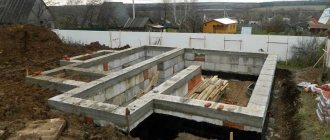
Plan of a strip foundation made of FBS blocks drawing.
Such holes and protrusions must be displayed on the diagram as contours and broken lines. Explanatory notes and footnotes may be provided if necessary.
Step-by-step instructions for installing MZLF
One of the most popular types of tape for private houses is a shallow foundation. This is a good foundation option that allows you to save on the amount of building materials, reduce the amount of excavation work and general labor investment.
Given the relatively shallow immersion depth, a high-quality survey of the site is required, including test drilling and determination of the groundwater level. This will make it possible to determine the composition of the layers and give grounds to predict the presence of problematic factors, heaving loads, etc.
These actions, as well as the creation of the project, must be performed by a trained specialist.
Further actions are carried out in stages:
Surface marking
The top layer of soil is removed from the site and, if necessary, leveled. Then, using stakes, the corner points of the future tape are marked. Cords are pulled between the stakes, compliance with the design data, orientation to the cardinal points and other parameters is checked.
Be sure to check the correspondence of the lengths of the diagonals. If they are not equal, you need to find the error and correct it in order to obtain high-quality and accurate markings.
Preparing the trench
After the marking has been made, trench digging begins. Excavation is carried out to a predetermined depth. Typically an excavator is used for this purpose, so the corners have to be adjusted and cleaned manually.
The excavated soil is stored on the sides of the trench, but most often it is removed or stored in a separate place.
The width of the trench must provide enough space for the installation of formwork, for which it is usually taken 30 cm larger than the design width of the tape.
Pillow for strip foundation
The sand cushion performs several functions:
- Leveling the bottom of the trench, forming an even horizontal reference line.
- Performing drainage functions.
- Receiving heaving loads and redistributing them along the entire length of the tape.
The usual thickness of the pillow layer is 10-20 cm. Some builders indicate larger sizes - 30-40 cm, but it is not recommended to follow such advice. The main task of the bedding layer is to level the bottom of the trench.
The thicker the layer, the greater the amount of subsidence. The sand must be compacted carefully, but some settling will occur anyway, so the thickness of the cushion should be limited.
Installation of formwork
FormworkThe higher the tape, the thicker the boards
When assembling, the maximum density of connections must be observed; all cracks are sealed with tow and wooden slats. The assembled panels are carefully lowered into the trench and installed in the desired position.
From the outside, the formwork is fixed with vertical and inclined stops; from the inside, cross members are installed that determine the width of the tape.
Installation must be done as firmly and accurately as possible, all fasteners must be placed outside to make it easier to dismantle the formwork later.
Reinforcement
The thickness of the reinforcement for shallow tape ranges from 10-12 mm for workers, and 6-8 mm for smooth rods.
You can make complex calculations, or use online calculators, but in the vast majority of cases the result will be exactly the same.
Traditional metal or modern composite reinforcement is used, which is non-corrosive and lightweight.
Knitting reinforcement
The reinforcement frame is assembled using the knitting method. To do this, you need soft annealed wire about 1 mm thick. The knitting process is simple - a piece of wire 25-30 cm long is bent in half, resulting in a kind of loop.
Then it is brought from below under the connection of the rods, the ends are raised up, grasping the connection. Then, use the end of a special hook to pick up a loop and twist it several times (4-6) around the other end.
The result is a strong and tight connection.
Selecting concrete for pouring
The most preferred option is to use concrete grade M200. It has sufficient strength, resistance to loads and external influences.
It is not recommended to use less durable grades, since concrete has large quality tolerances and may turn out to be very weak, although the grade of the material will be maintained.
The use of M200 concrete is guaranteed to provide the required quality of the material.
Fill
FillingIt is made from several points evenly spaced along the entire perimeter of the tape
The poured material is bayoneted or treated with a vibrating plate to remove air bubbles. Then the tape is covered with polyethylene to protect it from contact with sunlight. The formwork cannot be removed within 10 days.
At this time, periodic watering is necessary - for the first 3 days this is done every 4 hours, then for a week watering is done three times a day. Structural hardening is considered complete after 28 days of exposure.
Difficult sections of the diagram.
If you are planning to build a capital and large-scale structure, then it will most likely require the creation of a complex prefabricated or monolithic foundation. As a rule, such diagrams cannot be contained in one drawing. Therefore, experts in the construction industry strongly recommend developing separate plans for complex areas. Alternatively, you can apply additional centerlines and section designations (if necessary) to the main plan, as well as create large sections on the sheet, having previously made a mark about this. In addition, depending on the degree of section, it is recommended to choose a scale of 1 to 20, 1 to 25, or 1 to 50, in order to get the section and complex structural elements as close as possible.
Strip foundation plan drawing.
Design Features
The main reason why there is a need to develop a project for an object of any purpose lies in the need to fix details that may arise during the construction stage. It is important to take all this into account so as not to make mistakes during work.
Not every person is able to draw up drawings for construction. In this case, you should seek help from appropriate specialists.
A consumer who has his own sketches and contacts a construction company gets the opportunity not only to track the progress of the work, but also to actively participate in it. In this case, the customer should discuss all aspects of cooperation in advance so that the agreement turns out to be mutually beneficial.
Before creating a project, you should wait until they finish drawing up a site plan. To approve the project, you will have to contact the appropriate company that can check it for correctness. Only then does the customer receive a detailed list of work recommended to be carried out when pouring the foundation.
When creating a project, you should take into account the technical parameters of the future object. It is not recommended to use other people's drawings and calculations, because they may not take into account the specific features of the site allocated for development.
When designing a strip foundation, it is necessary to take into account all current technical standards and design conditions. A catalog collection for products and structures produced by domestic enterprises is required. To facilitate the process of understanding project documentation, each stage should have its own serial number.
To ensure that the diagram can be easily transferred to the terrain, it is recommended to maintain scaling. If there are particularly large images, they are made external with a separate scale indicated.
The transfer of drawings is facilitated using axial markings. It should be noted that the layout and lateral axes should be applied not only to the plan, but also to individual elements with detail views. In order for the drawings to be detailed and accurate, the distance from the extreme axis to the alignment axis should be indicated.
Additions to the scheme.
If you are going to create a monolithic or prefabricated type of strip base, then, to clarify the drawings, you should accompany them with the following technical documents:
- Scheme of reinforcement of the site based on the future load of the structure on the foundation;
- An application that displays the design features of a structure;
- Advisory explanations regarding preparatory work on the site;
- Tables and diagrams that are necessary for waterproofing and thermal insulation of foundations.
- Data on load standards on foundation supports.
Strip foundation plan drawing.
Constructive section: how to draw drawings and diagrams of individual elements
The structural section is an already detailed part of the project, which contains both general and individual data, various layouts of building elements: foundation, staircase structures, floors, trusses. Also included in this part are detailed drawings of all components, which indicate the specifics of products and materials.
The cross-sectional drawing of the foundation deciphers the dimensions of the strip fortifications of the house, the depth of their occurrence and the materials that are necessary for their construction.
The image of the foundation is presented in the form of the following plans and drawings:
- general foundation plan;
- longitudinal section diagrams;
- cross-sectional drawings.
Certain types of drawings provide a cross-section of floor slabs, their longitudinal and transverse sections at different elevations:
- overlap plan at point +0.00;
- at + 3.00;
- at an altitude of +6.00.
At the constructive stage, layout plans for the foundation, floors, and trusses are made.
Assemblies of structural parts are objects of a special structure, including stairs and flights both outside and inside the premises. Accurate calculations for strength and static strength are also given here.
This section of the project contains in separate tables the characteristics and sequence of use of materials, in particular:
- steel reinforcement;
- reinforced concrete elements;
- wooden crossbars.
Determination of the degree of depth.
As already mentioned, the depth of the trench to create a strip-type foundation is calculated depending on the scope of application of the supports. Today, two main types of structures are popular – deep and shallow. Once you decide which option is worth giving preference, the corresponding designation should be made on the plan.
- The first type of base is characterized by reinforced reinforcement and is an excellent choice for large structures, the design of which involves the creation of basements, attics or heavy partitions. It is believed that the most optimal indicator of the degree of deepening of a trench for a tape is an indicator that is 20-25 meters higher than the level of soil freezing depth in a particular region.
- The drawings certainly contain information about how deep the tape will be buried. It is important to remember that the amount of consumables for forming buried supports is an order of magnitude greater.
Strip foundation reinforcement plan drawing.
Additional drawing (complex reinforcement).
Laying FBS blocks
The choice of block width is determined by the thickness of the walls located above. The length of the blocks is selected so that they occupy, if possible, the entire tape. But even experienced builders make mistakes when selecting blocks: some unfilled areas remain, into which even the smallest elements do not fit (they are called additional ones). These areas are usually sealed with cement mortar bricks. If the masonry turns out to be uneven, it is then plastered: this will make it more convenient to apply waterproofing and insulation.
Typically, a prefabricated strip foundation consists of several rows of blocks. Their specific number depends on the required tape height. More often it is laid below the freezing depth of the soil. The required height of the base is also taken into account.
Construction of a block foundation. When laying cushion blocks, some areas remain empty. They are concreted after installation
When installing concrete blocks of any type, the same rule applies as when laying brick: the seams should not match. To do this, they are placed so that the seam of the previous row overlaps the body of the block in the next row. The gaps (vertical joints) between adjacent elements are filled with cement-sand mortar.
To give the structure greater strength and to connect all the blocks into a single system, reinforcement is laid on top of each row. Depending on the type of soil and the weight of the building, class A-I - A-III rods are used. The number of rods is determined by calculations during design; they can be from 2 to 5 pieces. When laying and connecting the rod, all the rules for reinforcing a strip foundation are observed - the connection of corners and partitions occurs according to the same pattern. The only difference is that there is only one reinforcement belt. A layer of mortar is laid on top of the reinforcing belt, and the next row of blocks is placed on it, with the seams offset.
To make the FBS foundation more durable with your own hands, it is reinforced
If these rules are followed, the prefabricated strip foundation will be strong and reliable.
Fundamental differences in support schemes.
Above, we tried to describe in as much detail as possible the process of creating a structure plan for which a strip foundation drawing is used. But at the same time, we should not forget that the drawings containing information about the prefabricated type of supports are fundamentally different from monolithic ones in that they contain a section, as well as a designation of straight and angular reinforced concrete structures.
Strip foundation plan drawing.
Dependence on the size of the structure
Designers calculate the parameters of the foundation, taking into account various influence conditions. The size of the house and its functionality is a fundamental factor in choosing the type of support and its dimensions. For industrial facilities, a powerful foundation is chosen that can evenly transfer pressure to the ground from vibration of equipment, shocks and electromagnetic vibrations.
If the soil under the house is weak, it is strengthened to reduce the amount of materials needed to construct the foundation of the house. The project includes a system for removing soil moisture from the underground part and waterproofing shells. Protective layers are shown in the drawing; materials and volumes are indicated in the explanatory note.
We carry out the calculations ourselves.
We assure you that today there is a sufficient amount of information available on the Internet in order to carry out all the necessary calculations as much as possible. To do this, it is absolutely not necessary to be an engineer or have a technical education. With a responsible approach to the issue, as well as being an observant and attentive person, you can easily calculate all the criteria necessary to create, for example, a strip foundation for a non-residential structure or a building envelope. It is important to consider the following:
- Vertical impact on the ground;
- The weight load of the main structure on the base;
- The weight of the roof and rafter system (but only if you are going to build a barn or non-residential outbuilding);
- When creating a foundation drawing, in order to eliminate errors, the results must be multiplied by “2%”. This will help protect against possible shortcomings during the independent design process.
Strip foundation plan drawing.
Principles of room arrangement
The layout of the rooms in a private house determines the level of comfort. Regardless of the number of floors, the mansion is conventionally divided into two zones: day and night or recreation. You can see the options in the house layout photos.
The day part of the project includes:
- kitchen;
- dining room;
- hall.
Designers sometimes include a terrace and veranda in it, where relaxation is carried out in the warm season. There is also a toilet and bathroom here.
In the night rest area there are:
- bedrooms;
- children's;
- wardrobe;
- bathroom with toilet.
Based on this principle, standard layouts of one- and two-story houses have been developed. The first floor is used for active pastime with the whole family. The second one is reserved for night time. If there are people in the family with limited mobility or elderly people, in the design of the first floor they allocate space for a bedroom and build an additional toilet with a shower. This layout is considered convenient, allowing you to fully relax and receive guests at the same time.
There is an opinion that it is better to orient bedrooms towards the southern sides of the house. This layout will allow you to fill the rooms with enough sunlight. The disadvantage is that in the summer the rooms will need air conditioning; this is achieved by installing household appliances and running them constantly.
Will the services of professional specialists be required to create the drawing?
Of course, a plan for a strip foundation for a residential building requires much more accurate and detailed calculations, which are best left to a specialist. When contacting a master of his craft, you can be sure that the drawing will:
- easy to read;
- as accurate as possible;
- meeting all SNiP requirements;
- containing comprehensive information about the preparatory work;
- having, in addition to the main drawing, technical applications in the form of various tables, diagrams, etc.
Strip foundation formwork plan drawing.
In this article, we tried to provide comprehensive information about the process and principle of creating a drawing of a strip foundation for residential as well as non-residential structures. And remember that if you are not confident in your abilities, then do not try to carry out the calculations necessary for such a basis on your own or using unlicensed programs. Saving in this case can be fraught with huge losses or even the destruction of the entire building or fence.
Explanatory note
The foundation design must include an explanatory note, in which the developer must include:
- initial parameters for the house design, on the basis of which the loads from the above-foundation part on the foundations are calculated;
- characteristics of the soil conditions of the construction site included in the calculation of the foundation structure;
- other natural and climatic parameters included in the calculations
- (normative and calculated freezing depth, predicted values of heaving deformation of unloaded soils, calculated heaving forces);
- boundary conditions for the structure of the house included in the calculations (level of responsibility of the structure, thermal conditions, absolute and relative heaving deformations permissible for structures of the above-foundation part of the house);
- basic principles of foundation construction technology;
- technical indicators of the foundation design.
In conclusion, it should be noted that obtaining a reliable foundation with significant savings in the cost of its production is possible only through a qualified approach and accurate calculations. Practice has shown that if at first the costs of the foundation seem too high to the developer and he does without design, then the costs of eliminating defects in the building many times exceed the supposedly saved funds. Expensive engineering-geological surveys and a developed foundation design may ultimately turn out to be cheaper than “free” foundation projects. We must always remember the saying about free cheese.
How to make a foundation drawing?
At the initial stage, it is necessary to determine the dimensions of the building, obtaining the four axes of the external walls. Then the axes of internal load-bearing walls and heavy partitions are added to the project, taking into account the following factors:
- enclosing structures must withstand the weight of cladding, ceilings, rafter system, roofing
- When choosing a wall material that needs protection from getting wet and solar ultraviolet cladding, it is more rational to use a ventilated façade with insulation inside it.
- then all loads on the foundation and the soil underneath are collected (the weight of structural, cladding materials of the roof, ceilings, walls, wind and snow loads)
- after which, you can calculate the width of the sole
Then on the sketch it is enough to add two lines (inside, outside the perimeter) from the axes of the strip foundation. The formwork panels will be mounted along these cords; the string along the axial lines will make it possible to control deviations in the geometry of the monolithic foundation.
Plan of a monolithic strip foundation drawing.
The simplest design method.
When calculating individual elements of a strip foundation , tables SP 22.13330 or V. S. Sazhin’s Guide will be required. The technology for calculating the width of the tape is as follows:
- prefabricated load calculation
- soil determination visually or by rolling into a rope
- dividing the resulting figure by the calculated soil resistance taken from the tables for specific soil on the site (minimum value to compensate for possible errors)
Strip foundation plan drawing.
The burial depth for MZLF is 0.3 – 1 m depending on the groundwater level. Recessed strips are lowered below the freezing mark by 0.4 - 0.6 m. The height of the basement part of the foundation depends on the preferences of the developer:
- by pouring the tape at 10 - 20 cm from the ground level, you can create a floor on the ground, sharply reducing the construction budget
- when lifting by 40 - 60 cm, a ceiling on beams or a slab is used; ventilation vents are required in the basement
- if an underground floor is planned, the height of the basement depends on the level of the finished floor in it
Based on the calculation results, it is possible to prepare a drawing for moving the axes to the building site and carrying out excavation work.
Sketch of a strip foundation.
To accurately draw a monolithic foundation, you need access to professional graphic editors AutoCAD, Compass, Solid Work, Archikad. Therefore, paper sketches are often used for garden buildings. On it it is necessary to mark the axes of the walls, auxiliary structures (stove, internal staircase, porch, fireplace), and draw the contours of the foundation strip.
Reinforcement scheme.
Foundation plan drawing how to draw.
For any strip foundation, reinforcement is necessary if it is planned to manufacture a monolithic structure on site. The layout of the lower and upper reinforcement frame can be depicted in the same drawing. You will need it to draw up estimates when purchasing rods, wire, spacers, and stands. When drawing a diagram, you must consider:
- It is prohibited to overlap the rods in the corners; the reinforcement is bent at right angles and overlapped on the adjacent side of the tape
- when extending rods along the length, the overlap should be 60 - 70 cm
- in wall joints, the rods are joined similarly to the corners (bending, launching to the adjacent side)
- the protective layer (distance from the concrete surface to the reinforcement) is 1.5 – 4 cm
Strip foundation reinforcement plan drawing.
When the belt width is less than 15 cm, one rod in each belt is sufficient. In wide tapes, the minimum distance between the rods (in the clear) should be more than 35 mm (bottom), 40 mm (top). Reinforcement is needed in the lower part at the sole, near the upper edge of the structure. In the middle part, the tape is reinforced only when it is high (from 0.7 m).
Plan of a one-story house up to 100 sq. m – construction of a building for a comfortable life
One-story houses with an attic, up to 100 sq.m. can be an excellent solution for small areas located within the city. Such structures are very popular due to their affordable cost and low physical costs for construction. Moreover, for construction you can use different materials, from wood to concrete blocks.
PHOTO: z500proekty.ru/projekt/z72.html The simplest, modest, but beautiful option
There are a number of advantages of a small house with an attic:
- high speed of construction and design;
- less material costs for foundations and building materials;
- it is easier to provide the entire room with the necessary communications;
- you can order a ready-made project of economy or luxury class;
- the building can be erected on almost any type of soil without fear of destruction or settlement of the house.
PHOTO: z500proekty.ru/projekt/z71.htmlThe design with an attic will provide additional space
The disadvantages include limited space and layout options, since only 3-4 full rooms can fit on the ground floor.
PHOTO: z500proekty.ru/projekt/z7.html Option with a small terrace
Among typical projects, the following dimensions are distinguished:
- 6×6;
- 9×9;
- 8x10 m.
Each design has its own characteristics, and externally can be made in any design, distinguishing your home from others.
Plan of a one-story house 6 by 6 m: interesting photo examples of finished work
Planning a one-story cottage can take a lot of time, but the construction process itself, with a well-prepared plan, will go much faster
In a small house, it is important to take into account the correct arrangement of rooms with the most rational use of the entire living space
Among the plans for small houses 6x6 m with one floor you can find very interesting options. Here are some photographic examples of schemes and finished buildings:
Simple layout
Option with one large living room
House plan 6x6 m with attic floor
You can choose a slightly larger project 6x8 m
The living area in such a modest room is only 36 m², but even in such an area you can arrange a sleeping room and a living room, and move the nursery to the attic. It is better to make the bathroom combined, freeing up space for the kitchen or hallway. Such designs are often chosen by elderly couples or small young families with one child.
Plan of a one-story house 9 by 9 m: photo examples with room distribution options
There are quite a lot of layouts for a one-story house 9 by 9 m, despite the modest living space. You can make a plan yourself or order a ready-made version from the masters. Here are some interesting room layout options:
Location of rooms with two bedrooms
Corner layout. You can make a big porch
Option with terrace
Example with an attic
A one-story house 9 by 9 m can be built from brick, stone, timber, energy-saving panels or foam blocks. The last option is the most affordable. A garage or attic can be added to any structure to make the space larger and more functional.
On average, the total living area will be 109 m², and the facades can be very diverse. Here are some ready-made beautiful houses 9x9 m:
Layout of a one-story house 8 by 10 m with photo
When planning the construction of a house and drawing up a project, it is worth thinking through many nuances, ranging from the number of people in the family, ending with the location of the building on the site with the choice of window location.
Modern technologies make it possible to create 3D designs of one-story houses 8 by 10 m, taking into account their location on the site. To do this, they use special computer programs, where it is even possible to distribute rooms and arrange furniture.
3D design option for the exterior of a house
There are many layouts and options for distributing living rooms; you can choose a project for a one-story 8x10 house with an attic or an attached garage, and also think about the basement. All this allows you to maximize the usable area of the building.
Here are some interesting layouts:
House with attic, ground floor plan
Ready-made designer house made of wood with a large open terrace
3D modeling of the location of the house on the site
Option for the location of rooms with an attic floor
Construction technology.
For a monolithic foundation, a standard construction methodology is used, consisting of the following stages:
- full-scale axle offset
- trench/pit excavation
- filling the foundation cushion
- sole waterproofing
- installation of formwork
- reinforcement
- concreting
- surface waterproofing
To reduce heaving forces, the blind area and the side surface of the tape are insulated, and drains are laid at the level of its sole. At each stage there are nuances that make it possible to reduce the amount of work and increase the service life of the structure.
Marking, pit.
Before moving the axes into the construction site, it is necessary to place the building on the site for normal operation of engineering systems, fertile soil, and the dwelling itself. For example, there is often parking on the street side; an external sewage septic tank requires periodic emptying, so it is also located closer to the street. It must be at least 4 m away from the foundation to ensure a sanitary zone.
Strip foundation plan drawing.
Power transmission poles and wells with shut-off valves for connection to central life support systems are also installed here. The front facade is most often turned towards the roadway. After this, it is enough to mark the strip foundation according to the scheme:
- first wall – starting corner 3 m from the boundaries of the site, spine 5 m from the red line (street road)
- side walls - perpendicular to the first axis (construction of a triangle with 4.3 m legs, 5 m hypotenuse)
The corners of the last wall (the rear facade of the house) are obtained automatically. During excavation work and the manufacture of the foundation pad, the cord must be periodically removed. To avoid repeated measurements, castoffs are recommended - a horizontal block between two pegs. You need 2 of them for each axis; three strings can be pulled across wide slats at once (the side edges of the foundation, the axis of the wall).
Cushion, formwork.
The layer of non-metallic material under the bottom of the monolithic foundation is intended to replace heaving material and level the bottom of the trench. The most popular underlying scheme is:
- sand 20 cm + crushed stone 20 cm – laid on geotextiles, wrapped with it on top after compacting every 10 cm
- crushed stone + sand (the thickness is similar) is a more convenient option; an extra layer of geotextile is added between these materials, but there is no need to fill the footing when laying roll waterproofing
- sand 40 cm or crushed stone 40 cm - the first option only for low groundwater levels, the second for high groundwater
Rolled waterproofing (usually hydroglass insulation) is laid in 2 - 3 layers with a release so that after concreting it can be rolled onto the side edges of the tape. The formwork is mounted on top of it; it is better to use materials that can be reused (OSB, plywood, edged boards).
Vertical panels, the height of which is 5 cm greater than the design mark, are supported against the sides of the trench, the ground, and fastened with jumpers (pins, bars). In the underground level it is necessary to leave openings for the introduction of engineering systems, in the basement part of the ventilation duct. To do this, pipes are passed through the shields, which remain in the concrete for sleeves or are pulled out when stripping.
Strip foundation formwork plan drawing.
Reinforcement, filling.
The aromatic frame of a strip foundation is usually two-level. For light buildings, two corrugated rods in the upper chord and two in the lower are sufficient. To fix the rods inside the formwork, rectangular clamps are used, curved from smooth 6-8 mm reinforcement, to which longitudinal reinforcement is tied with wire. The main requirements are:
- spacing of joints in adjacent rows by 60 cm minimum
- bend at the corners
- overlap from 60 cm
Strip foundation reinforcement plan drawing.
The bottom bars rest on polyethylene supports or concrete pads to provide a protective layer. pouring occurs according to standard technology with compaction along a ring of every 60 cm of concrete to remove air.
Waterproofing, drainage.
For a monolithic foundation . partially or completely immersed in the ground, protection from moisture is necessary. This is done in several ways:
Strip foundation waterproofing plan drawing.
- waterproofing the outer edges of the tape - penetrating products, coating with bitumen mastic, gluing with Gidrostekloizol or the last two options in combination
- drainage system – placed around the perimeter at the level of the tape sole
Foundation pit plan drawing.
A storm drain (storm inlets + surface gutters) is built into the outer perimeter of the blind area, with the help of which melted rainwater is drained.
The above technology is suitable for strip foundations of any type, deepening. Recommendations from experts will help avoid mistakes and reduce the labor intensity of construction operations. The housing will have a high service life, despite independent calculations.
Optimal distance for various buildings
You cannot rely only on the size or purpose of buildings, since in addition to the weight of the house, the type of soil plays an important role.
The denser the underlying layers, the smaller the width of the tape can be made during construction.
For auxiliary and utility buildings, the width of the tape is allowed:
- Dense (rocky) soil, clay - 25 cm.
- Loam - 30 cm.
- Sand, sandy loam - 35 cm.
- Soft compacted sand - 40 cm.
- Very soft sand - 45 cm.
For one-story light houses (dacha, frame house):
- Dense (rocky) soil, clay - 30 cm.
- Loam - 35 cm.
- Sand, sandy loam - 40 cm.
- Soft compacted sand - 45 cm.
- Very soft sand - 50 cm.
For two-story cottages:
- Dense soil - 50 cm.
- Loam - 60 cm.
- Other types of soils do not have average indicators and require separate specialized calculations.
It must be borne in mind that average values are rarely suitable for specific situations, since there are always a lot of additional factors not taken into account in the tables.
The impact of these factors can radically change operating conditions and require a separate calculation, sometimes made using a completely different methodology.
General information.
The foundation in the concept of construction is the underground part of the building (structure), which receives loads and transfers them to the base. If you look at the drawing of a monolithic base, you can highlight the following parts. The base is layers of dense soil. The upper plane on which the above-ground parts of a structure or building are located is called the edge or surface. Its lower plane, which is in direct contact with the base, is called the sole.
Residential building foundation plan drawing.
The tape is laid around the perimeter of the building.
A strip foundation is a strip of reinforced concrete that runs along the perimeter of the entire building. The tape is laid under all external and internal walls of the building. The construction technology is quite simple compared to pile or slab construction. To build a strip foundation, a drawing is required. Such a foundation is labor-intensive and requires a considerable consumption of materials compared, for example, with a columnar type (more concrete, formwork; you will definitely need to use a crane).
Tape can be used:
Strip foundation plan drawing.
Strip foundation diagram
- In houses with concrete, brick and stone walls (the density of which is more than 1000-1300 kg/cub.m).
- For houses with heavy floors (precast reinforced concrete or monolithic, metal).
- If there is a threat of uneven precipitation due to heterogeneity of soils on the site (for example, the site in one part is composed of sands, and in the other - heaving loams). A reinforced strip base can work as a single whole, redistribute forces, and then the walls of the house will not cause deformation or cracks.
- If you plan to have a ground floor or basement in the house and the walls of a similar strip structure will form the wall of the basement.
In the process of planning the construction of a house, it is quite important to competently and responsibly approach the choice of the type of structure being manufactured, because this element is one of the most important structural elements for construction. An error at the beginning of construction, saving building material, an incorrectly designed structure, or an incorrect drawing will lead to serious negative consequences during the operation of the house.
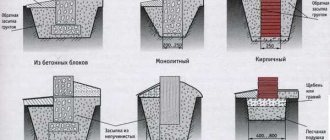
Strip foundation plan, section drawing.
Structures: a, b) prefabricated, c) monolithic, d) rubble.
Problems may arise such as distortions, excessive consumption of materials, horizontal and vertical deformations, uneven settlements, cracks in supporting structures, and so on. To a great extent, a large number of qualities of the building will depend on reliability, in addition to its durability and capitality.
It should be remembered that the zero cycle of building a building is a somewhat expensive process, and most often it accounts for a third of the cost of the entire building. It is best to order a project and drawing from experienced designers. It is worth understanding that you can ask them only if you draw up the contract correctly. The organization in the project can reasonably and competently choose the type and material with which the foundation can be made.
Selection of support pillar material
The reliability of the foundation structure largely depends on the correct choice of material for the support posts. At this stage of construction, you should not try to save money. If at the moment the purchase of inexpensive materials will allow you to save some money, then in the future you will have to spend very significant sums on repairs and correcting defects.
For the construction of a columnar strip foundation with a monolithic floor slab, you can use:
- wood;
- rubble stone;
- solid red brick;
- aerated concrete, foam blocks, slag concrete or concrete blocks;
- asbestos-cement, concrete, plastic or metal pipes;
- concrete pillars;
- pre-fabricated and bored columns.
Each material has its own characteristics, which are described below.
Wood
The main reason for the low popularity of wooden foundations is their fragility. Even additional treatment to protect against moisture, rot and insects increases the service life for a short time. However, wooden beams can be used to construct grillages raised above the ground in the construction of light utility and domestic buildings.
Rubble stone
This material has long been known to builders and has been widely used for the construction of foundation structures. It is distinguished by great strength and durability. However, its laying requires highly skilled mason skills to fit individual stones to each other. Therefore, only a professional builder can lay reliable rubble stone pillars.
Types of columnar foundations: a. brick pillar on a rubble base; b. solid brick pillar; V. brick pillar on a concrete base; d. burnt wooden chair (oak or pine); d. metal stand; e. rubble pillar.
Bricks and blocks
For the underground part of the foundation structure, only high-grade clinker or solid clay bricks can be used. In columnar strip foundations made of bricks and blocks, the above-ground part of the grillage is laid out, located on a concrete monolith.
Considering the hygroscopicity of these materials, a surface coating with bitumen waterproofing in several layers is required.
Pipes
The use of asbestos-cement, concrete, plastic or metal pipes is advisable as permanent formwork, inside which a reinforcement frame is installed and concrete is poured. As a result, you can quickly obtain reinforced concrete pillars of high quality. Metal materials must be provided with a waterproofing coating to protect against corrosion.
Types of columnar foundation.
Concrete pillars
Vertical pillar supports made of reinforced concrete are made on site after drilling or excavating wells. The structures are poured inside removable or permanent formwork after installing the reinforcement cage. In addition, individual poles or prefabricated piles can be purchased. They are installed at points with the greatest weight load and then tied with a grillage.
Rammed and bored posts
They are purchased ready-made on the building materials market. Installation is carried out using special driving equipment directly at the installation sites. Structurally, these are hollow reinforced concrete supports, inside of which a metal frame is installed and concrete is poured. Columns of both structures may be used together.
Impact diving or vibration diving?
When piles are driven into the ground by impact, there is a strong dynamic impact that reaches the foundations of nearby houses. Therefore, this method is not acceptable on tight city streets.
The installation of reinforced concrete piles using the vibration driving method is carried out using vibratory hammers, which exert small-amplitude dynamic impacts on the piles.
This method is best suited for non-cohesive soils: sandstones, sandy loams, gravelly sands and wet soils. Vibratory driving of piles in cohesive soils is possible only when their density is low.
Expert advice! In dense soils, vibration driving is combined with leader drilling - first, a well is created into which the pile is driven.
Drawing the second floor
Here everything will be much easier - after all, the rooms in the house can be located identically (the most important thing is not to change the relative position of the bathrooms - in order not to complicate communications). It will be enough to design the location of the front door (many architects recommend making two entrances to the second floor - at home and from the street) and windows.
Step 5: We plan the premises of the second floor in the same way. Don’t forget about communications - we place the bathrooms and bathrooms one below the other
Step 6: Place the Doors
Step 7: draw the second floor windows
We received this 3D model of the second floor