To optimize the control of lighting fixtures throughout the house, a system device is used. It helps you turn off the lights with just one button.
The system apparatus consists of individual elements:
1) Contactor is an electromagnetic switch that is designed to remotely close and open electrical circuits.
2) Control module, which consists of:
- a regular 2-key switch.
- electric key scanner (contactless) and cards;
- Wi-Fi or GSM remote control unit.
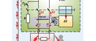
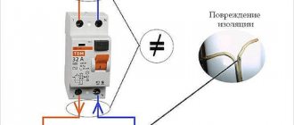
3). An RCD is an automatic device equipped with a protective shutdown mechanism and ensures the safety of the entire system.
Residual current device Source shikalad.ru
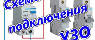
We connect the lighting in the house with a master switch: diagram
To implement such projects, you will need modular contactors for the master switch, for example, ABB ESB 20-20.
The letters and numbers in the name have a specific meaning. The marking symbols mean:
- АBB – name of the organization, manufacturer of the device.
- ESB – circuit breaker series, has a household purpose.
- 20 – current value calculated for the contact element, in A.
- 20-20 – independently closed block contacts with a rated current of 20 A.
Before the pulse arrives, the contact elements are constantly in the open state.
Video description
Master switch. Contactor. Connection diagram.
Contactor connection diagram
It is assembled in the following sequence:
- The single-key light switch receives voltage.
- The current passing through the switch comes to connector A2 on ABB ESB 20-20.
- Its other contact (A1) is permanently connected to “zero”.
The phase conductor is connected to the 1st connector of the contactor, and the wire connecting the lighting devices is connected to the 2nd.
Single-line diagram of a distribution board master switch Source zen.yandex.com
The system operates on the following principle - when you press the light switch button, voltage comes to contact A1, in fact to the contactor coil. Then, according to the law of electromagnetic induction, it becomes closed. In the absence of voltage, contact A1 is open.
After it closes, electric current flows to the equipment. If you press the button of the single-key light switch again, the line is de-energized. Inside the circuit breaker, the connection is broken and the consumer is disconnected from the voltage.
Another group of lighting devices with a rated current of up to 20A is connected to connectors 3 and 4. In total, the control device can withstand a load of no more than 9-10 kW with an allowable current of 40A.
If you assemble a circuit without a contactor, passing the phase of the power cable that connects all groups of lamps through a single-key switch, serious problems will arise:
- A maximum current limitation is created.
This is the value that the switching element that turns off the light can withstand. The value for a single-key switch is rarely more than 10A.
- The switch will quickly fail.
This is due to the fact that it does not have a contact protection system. Therefore, the terminal pads burn out or the housing melts. Sometimes fires happen for this reason.
Normally open or closed contactor - which is better?
Also look at the design of the device. Contactors are available with normally open (NO) and normally closed (NC) contacts.
Mistake #4
We'll need open ones, not closed ones.
This means that when no voltage is supplied to the starter's closing coil, the power contacts remain open and no current flows through them.
Here is the corresponding drawing and designation of such a series on the device body.
It would seem that a contactor with normally closed contacts is much better, because its coil will not be under 220V voltage all the time.
However, always take into account and take into account not only normal modes, but also emergency ones.
In an emergency (damage, fire and failure of the control coil), your entire switchboard and devices remain energized. But this shouldn’t happen.
When the introductory circuit breaker gets stuck, a serious problem arises with de-energization of the entire house.
Also, the solenoid coil at the NO (normally open) contactor will be energized when you are at home. Whereas with NC equipment when you are not at home. Roughly speaking, the NO contactor will buzz when you are nearby, and the NC contactor will buzz when you are far away.
Think of it as a vacation of almost a month or more. The second option (NC) is less safe and in your absence you simply will not be able to quickly respond to the development of an emergency situation.
Master switch: turn off the light with one button
Some residents associate turning off the lighting throughout the apartment using one button with the Smart Home system, since it is not clear how it works. If we control all the devices, when all the lamps are connected to one controller, then the simplest action is to turn off all the lights at the same time before leaving the house.
This function is implemented very simply; you do not need a “Smart Home” for this. For this purpose, a contactor is installed in the electrical panel, equipped with the ability to turn off the lights in all rooms at once based on an external signal. Some people put an additional device on switched sockets.
The contactor, which simultaneously performs the function of a starter, is a modular element mounted on a DIN rail. The mechanism, based on a control signal, turns off and turns on a powerful load, for example, an ABB ESB 24-40 contactor.
Causes
The problem of two phases appearing in sockets or on switches is not new, and can arise unexpectedly at the most inopportune moment, as in our case in the evening. In this case, electrical appliances do not burn out; they simply stop working.
But it is important to understand that the light can disappear in one or two rooms at the same time, and two phases will appear only in sockets, or vice versa, only in switches (rarely in both cases), thereby stopping the computer, the Internet, etc. But this problem may not affect the kitchen at all.
Why don't electrical appliances burn out? You ask. Yes, because in fact there are not two phases in the outlet, but one. If you take a multimeter, not a probe, and measure the voltage at the terminals of two wires (phase and zero), the device will show “0”. Those. 220V has disappeared somewhere and there is a dilemma - where? And why then does the probe show two phases? The reason for this phenomenon lies in the zero break.
Those. in a normal situation, the electric current flows through the phase wire and returns through zero, while it passes through the switched-on electrical appliances, powering them.
When the zero is broken, to put it simply, the phase does not go to the zero bus of the shield, but remains on the wire and we observe it on the probe. But in reality there is no potential difference between the wires, which is why the multimeter shows “0”.
But we can also observe the following picture: the appearance of two phases in sockets when all electrical consumers are turned off, i.e. the circuit is not closed. And if we adhere to the theory, then the phase current should not return. But for some reason the probe lights up brightly on one wire, but fades on the second.
Here you need to remember about electromagnetic induction. The phase and neutral wires pass very close to each other and due to the electromagnetic field, a slight voltage is generated in the neutral wire, which we see on the probe in the form of a faded glow. If the zero breaks, he also has nowhere to go.
If, for example, you turn on a lamp in the network, then the probe on the neutral wire will burn brightly. At least that's how it was for us.
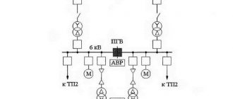
Hotel circuit and master switch
When there are a lot of lamps and other electrical appliances in the house, and all of them are needed, you can do without turning them on and off at the same time. This is done due to the cross-section of the wires and the current strength of the circuit breaker.
To do this, it is necessary to arrange the electrical wiring in such a way that the circuit diagram includes several circuits that have their own separate circuit breakers. It won't be difficult to do this. With this option, specific groups of electrical appliances are connected to each circuit. Due to this, when all devices are turned on simultaneously, regardless of their power, the current strength in circuit breakers and electrical wiring will not go beyond critical values. This type of electrical circuit is called “hotel” in professional circles.
“Hotel” diagram for connecting a master switch Source rusmarta.ru
To sell you will need to additionally buy:
- a little cable (30-40);
- the required number of machines (depending on the number of circuits);
- master switch, which controls automatic switches through relays.
In appearance, it is a simple key located at the entrance door to the apartment. Such a device allows you to easily turn off the lights in an entire room or turn off a specific group of electrical appliances with a single click.
Features of installation of hidden and overhead types
According to the installation method, switches are divided into internal (hidden) and external (overhead). Although the principles of their installation and operation are the same, there are differences in the approach to installation.
Installing an internal switch
Such devices are more aesthetically pleasing; they are recessed into the wall, but they require a special recess in the surface and the installation of “glasses”. Therefore, they can only be mounted in a wall of sufficient thickness. Devices of this type are used in conjunction with hidden wiring.
Video on the topic.
Installing an external device
These devices have disadvantages, mainly of an aesthetic nature. They perform their function of opening and closing the circuit no worse than internal ones. But their installation is simpler - there is no need to arrange a socket box, only an overlay on the surface is required. Another plus is the ease of mounting on plasterboard walls and partitions. Surface-mounted devices are used in conjunction with external wiring, but can also be used for hidden wiring - you just need to bring the ends of the wires out near the installation site of the device.
Surface-mounted device for outdoor installation.
How to equip the system device
The connection diagram for the master switch depends on where it is planned to be used. Different rooms have their own characteristics, so a competent approach is needed.
In the circuit diagram, the circuit breaker is located at the beginning of the electrical circuit. In fact, it is located in the house next to the meter.
Connection diagram for modular contactor Source strojdvor.ru
The operating principle of the circuit is based on the fact that the consumer sets the maximum permitted power consumption, which is required in total for all devices connected to the network. If the parameter exceeds the permissible limit, after a short period of time the circuit breaker will trip and completely de-energize the room.
Due to imprudence, such a decision does not suit the homeowner. Turning off the lights at the most inopportune times creates certain problems with cooking on an electric stove. However, such measures are associated with the need to ensure fire safety. In the event of a short circuit or current leakage, the light turns off instantly.
What colors should the wires have in the electrical wiring of an apartment?
Any conductor purchased for electrical wiring must contain a core with a blue (blue) braid. It is this that is recommended to be used in the network as a neutral wire. If the apartment has a third wire - direct grounding, it is recommended to run a yellow-green wire on it. All other wires (it can be white, brown, black, etc.) are used as phase-carrying wires. So to the question whether the switch breaks phase or zero, the answer will be unequivocal - phase, and this core will not be blue or green.
If the wires in your apartment are mixed up, it means that the installation of electrical wiring in it was not carried out by professionals and, most likely, it has already undergone repairs.
Master light switch: technical implementation
There are 3 key decisions regarding technical implementation.
- The contactor and master button are installed in the electrical circuit that powers the lighting group.
Before installation, it is better to have a schematic diagram before your eyes. When you press the switch button, the contactor supplies power from the group circuit where the apartment's lamps are connected. This is the most popular option.
- Centralized switching on and off of lights.
Lighting is controlled using a master switch if the entire lighting network in the house is mounted on pulse relays. This option is more expensive and complex; additional special modules are used.
Centralized turning on and off of light in the presence of a pulse relay Source uk-parkovaya.ru
- The most functional and universal solution.
With this option for connecting the master switch, a PLC (programmable logic controller) is used. Thanks to programming, it is possible to change the lighting scheme. Depending on the selected equipment, it is possible to reduce the cost of this option compared to the cost of pulse relays.
Possible consequences and danger of the appearance of two phases
Two phases in a socket give zero potential difference
When a particular outlet has 2 phases at once, you must first of all worry about what this threatens for the people using it. This situation is unacceptable for the following reasons:
- The potential difference between the socket terminals will be 220-220=0 Volts.
- The voltage will be lost and connected household appliances will not work.
- A danger arises due to the loss of the protective grounding circuit, which in old houses operates through an earthen conductor (due to the lack of a local circuit).
In this case, there is no need to talk about any protection at all; the consequences may be unacceptable to people. An ignorant electrician, believing that he touches the neutral wire (in blue insulation), may find himself under high voltage. Therefore, the regulatory documentation requires that when disassembling installation products, it is imperative to check the absence of a phase on both terminals using an indicator.
In this situation, all or only the light switches connected to this junction box will also stop working. This is explained by the fact that a phase potential will appear on the neutral wire supplied to the chandelier, connected to the corresponding contact of the socket, and the voltage difference will become zero.
Placement of master switches and non-switched lines
System devices are usually located near the entrance to apartments, in the bedroom or office. These are places where it is more convenient to turn off all lighting devices, as well as centrally control the curtains.
To install non-switchable lines in the electrical panel, a switch or load switch is used to control switchable circuits. This solution is found everywhere.
Advantages of circuit breakers relative to master switches:
- simplicity;
- reliability;
- durability;
- compactness;
- low price.
Disadvantages of switches:
- not convenient to use, unlike master switches;
- non-switchable circuits require additional lighting installation;
- To ensure that devices are turned off and current is regulated, operations are performed manually.
The switch is built into the electrical panel Source grand-electro.ru
Additional lighting is done along the entire line to the electrical panel so that there are no problems in the dark when the lights are turned off throughout the house);
Master Button is a universal solution; it has everything you need. Without going to the switches located throughout the apartment, the device immediately turns off the lights everywhere.
Whether to install master switches or circuit breakers depends on the needs of the residents. The choice is influenced by the advantages and disadvantages of the devices.
Conclusion
If the electrician complies with the rules of the PUE, in particular clause 4.1.9, and respects his clients and colleagues, he will install the switch or switch correctly, i.e. on - up, off - down. Always check this before accepting work from an electrician. Unfortunately, not all electricians do their work conscientiously. Find out how experienced electricians can deceive their customers.
By the way, novice electricians will be interested in the following topics:
Source
How to connect a pass-through switch
Pass-through switches are used at the beginning and end of the electrical circuit, and a crossover switch is used in the middle of the line. There are other solutions, but less often.
The advantage of control circuits based on pass-through switches: simplicity and reliability. Flaws:
- it is impossible to automate the lighting control system;
- you cannot change the scheme after some time;
- cable consumption is high.
Sometimes a control scheme is implemented for 2 groups of lighting fixtures from N-places on 2-key pass-through elements. However, such a scheme is cumbersome and inconvenient in everyday life. Such switches do not have a fixed “On” or “Off” position.
Connection diagram for pass-through switch Source yandex.ru
Causes of incorrect connection
If the installation of electrical wiring and its connection to the network were carried out correctly, then a phase will be supplied to all switches. The presence of a zero indicates errors during electrical installation work:
- Incorrect connection of wires in the wiring box. It occurs when the color marking of wires is not observed or in wiring made in Soviet times with aluminum wire (noodles).
- Mixed up wires after replacing the electric meter or input cable. The meter must be connected taking into account the neutral and phase wires. After working on the device terminal block, the electric company inspector checks the connection for compliance and may require changing the polarity.
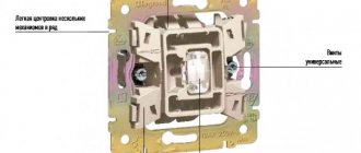
How to connect a switch with one key
The cartridge has 2 terminals; one of the cable cores is inserted into each connector and secured with a clamping screw, then the switch is connected. To do this, the device is disassembled with a screwdriver or by hand: the key attached to the plastic latches is disconnected. If it does not snap off, you need to push it from the back side. After unscrewing 2 screws, the decorative cover is removed.
The connection diagram boils down to the fact that you need to install a single-key switch in the “phase” break.
Connection diagram for a three-key switch Source svetosmotr.ru
Practical Application Examples
The digital device should be switched to dialing mode.
In this case, the same lamp can be controlled from each floor and, if desired, from the basement.
A pass-through switch allows you to close one of two circuits. How to make a pass-through switch from a regular one: work order. It is not always possible to quickly find a suitable model of a device that allows you to control lighting from two points at once. Connecting conductors using special WAGO clamps.
Let's look at the following circuit diagram: Three things have changed: From breakout box S1, switch S2 has two cables connected to it, which are used to power the other light switches. There are open type PV for connection with open wiring and closed type for connection with wiring running inside the walls. A diagram with two pass-through switches that allows control of two loads. The following video will help you understand in more detail the diagram for connecting a switch from two places: It clearly shows how to connect the wires in the junction box so that there are no difficulties during operation.
Electric lighting is an indispensable companion of any modern apartment. The first is used to connect a contact at the input, the second - at the output. To connect them, in the simplest case, you need two two-core cables. However, their functionality is very different.
Places of use In addition to the bedroom, similar situations can arise quite often. Before starting work, use a voltage tester to make sure that there is no electrical potential on the power cables, preferably on all terminals coming out of the box. The crossover device is connected between the feedthroughs. When choosing the appropriate option, you should buy a model with the same number of keys for each point. In such situations, it becomes necessary to control lighting from two places; it is for solving such problems that the so-called pass-through switches are designed.
Types of crossover and pass-through switches
With modern electrical installations, pass-through switches have become more often used, which can turn off or turn on, for example, the lighting in a room at the entrance to the room and at the same time near the bed or, for example, on both sides of the corridor. For the first case, socket boxes will be required for installation. It is also beneficial to use a similar scheme in small houses, the size of the floors. Electrical diagram for switching on a lamp from three places. An ordinary switch only closes and opens a circuit. Installing two ordinary switches in different places in the room will not allow you to control the lamp from two places at once.
Similar to switch S1, we connect the protective conductors with one connector and the neutral conductors with the help of a second connector. Conclusions and a useful video on the topic You can learn from the videos presented how the use of circuits for connecting pass-through switches from several places occurs in practice. Thanks to these jumpers, the phase to the lighting source can be supplied from either one or a second switch, which will allow you to turn on the lighting from several places. Such solutions are useful in large houses and small apartments. In order not to be mistaken about what kind of switch it is, you should familiarize yourself with the connection diagram, which is present on the switch body. Connection diagram for a two-key pass-through and crossover switch from two or more places.
How to connect a three-key switch
Connecting a 3-key switch is done in exactly the same way as one and 2-key switches. The difference is in the number of contacts of the outgoing groups: 1, 2 or 3. One supply cable is connected to the input terminal of the switch, and the wire of the lamps is connected to the “output” contacts. The neutral conductors of all lighting devices are combined into one circuit and connected to the “zero” in the box.
Connection diagram for 3-key switch Source vodakanazer.ru
Installation of protective equipment
Next, you should take a closer look at the systems. In order for the power station to be fully functional, it is necessary to think about a device that protects against unexpected overloads, as well as short circuits.
Here you need a two-pole circuit breaker (you can replace it with an RCD or a circuit breaker with a voltage limiter).
The next step is to distribute the wires correctly. You should know that the blue wire goes to zero, the white wire goes to phase, and the yellow wire goes to ground.
- Using a sharp knife, carefully remove about one centimeter of insulation from each wire. Then the stripped tip is inserted into the contact terminal and secured with a screw. It's worth giving it a little tug to make sure it's securely in place.
- By analogy, the wire is connected to the distribution box. You should be careful and not confuse colors. Sometimes manufacturers change the shades of the phase and ground wires, but the neutral wire will always be blue. To avoid confusion in colors, you should always use wires from the same manufacturer.
- Next, the outer insulating layer is removed, the required piece of wire is measured, which will be needed to connect to the circuit breaker, stripped again and screwed on. The insulation is removed from the remaining wires, after which they are also connected to the machine.
A wire consisting of three cores is used in this case for a reason; the fact is that this is done for the future, i.e. Perhaps over time you will want to change the lampshade to a chandelier, this is where the third core will come in handy.
After all, it is much easier to perform another twist than to completely change the pattern. In addition, the third core can serve as grounding. This should be done if the lamp has a metal body or the room has high humidity.
To connect grounding, you must:
- Take the contact clip;
- Measure the required piece of wire
- Clear it;
- Join;
- Tug to determine the reliability of the connection.
A similar procedure is repeated on the outgoing piece of wire. That's all the machine is connected. Everything is located in the distribution box.
Lighting control circuits through contactors and magnetic starters
To switch on contactors and magnetic starters, push-button posts are used. This is a device equipped with 2 buttons: “Start” and “Stop” or 3: “Forward”, “Stop”, “Back”. These elements are without fixation, with closed and open contacts.
The lighting control circuit is simple and is shown below.
Magnetic starter connection diagram Source uk-parkovaya.ru