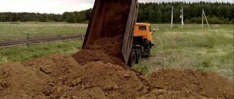
Road drainage is necessary to remove water. There must be drainage of highways, because they do not absorb moisture, which can destroy the road. This is why drainage is common near buildings to protect the foundation and along roads. But, there are other reasons that influence the fact that people take up drainage of the area near their home. But, more about them later. This article will tell you how to make road drainage, what types of drainage systems exist, what tools you will need, as well as how to think through all the nuances and what you should pay attention to first.
When is drainage ditches required?
The need to drain water from a site arises when water accumulates in large quantities on the surface of the earth and is poorly absorbed into the soil.
Water drainage from the site is also required in the following cases:
- the location of the territory in a lowland, where melt and rainwater flows from higher places;
- water seepage, damp smell or mold in the basement or subfloor;
- swampy area, wet ground even in the hot and dry season;
- puddles that do not dry out for a long time after snow or rain melt.
If the site is located on an elephant, to prevent erosion of the fertile soil layer, transverse drainages should be installed to intercept and drain water into storm drains, storage tanks and other suitable places.
The need for soil drainage can be determined after a hydrogeological study of the soil on the land plot.
If the site has a high level of groundwater, measures for water drainage must be provided at the stage of building a house.
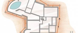
Drainage ditches in an area with difficult terrain.
Useful tips for arrangement
If there is a need to turn the pipe 90 degrees, it is better to organize two 45-degree bends. This will reduce the sharpness of the turn and create minimal resistance in the network.
If a turn of 90 degrees or more is achieved, a manhole is installed at the junction. It smoothes the turning angle and prevents clogging
It is impossible to organize drainage from the roof to the blind area. This will lead to waterlogging of the soil around the building and loss of its bearing capacity.
The surface water drainage system and foundation drainage should not be combined. Their joint work is dangerous due to rainwater entering the drainage and flooding the foundation.
Don't forget to add taps to the system that will prevent flow redirection in emergency situations or during repairs.
Laying methods
Drainage ditches can be open or closed.
- Open drainage ditches are trenches located in areas of greatest accumulation of water. They are used to drain surface melt and rainwater and are especially effective for draining areas located on a slope.
To prevent the walls from collapsing, trays made of plastic, polymer concrete or reinforced concrete can be installed at the bottom of the trench. The trays are covered with decorative grilles on top for safety purposes and to protect them from leaves and debris.
The walls of the ditch can also be reinforced with metal meshes - gabions, natural or artificial stone, turf, special plastic geogrids and other materials.
- Closed drainage ditches are more complex in design.
Such structures are constructed by laying drainage pipes in trenches. Water enters the drains through the perforated walls and is removed by gravity outside the site or to specially designated areas. To prevent siltation, pipes are covered with drainage crushed stone and wrapped in geotextiles. From above, the drainage is filled with plant soil and sown with lawn grass.
The number of ditches depends on the height of the snow cover on the site, the degree of soil moisture during the rainy season and the depth of groundwater.
When installing open ditches, it is necessary to make the walls as airtight as possible so that the water, without being absorbed, goes into the storm drain.
Scheme of a closed drainage device.
Summarizing
The practice of users of our portal suggests that a way out of any situation, even the most hopeless one, can be found. If you lack experience or self-confidence, you can always seek advice from experienced FORUMHOUSE members, who will always tell you what and how to do correctly during construction. And even without a large budget, with the right approach you can make a reliable and inexpensive storm sewer and site drainage system with your own hands.
A thread on FORUMHOUSE explains how to drain and drain a wetland. We also advise you to study the topic, which gives advice on choosing geotextiles for the drainage system.
Useful articles about the features of the drainage system of the foundation and site, the choice and independent installation of a drainage well, and what to do if the basement floods.
The videos contain the nuances of site drainage and tips on choosing drainage pipes.
Classification of drainage ditches
The problem of soil waterlogging by storm drains, groundwater and flood waters is typical for country houses and summer cottages, highways and park areas.
The underground structures of houses suffer, roads and sidewalks are destroyed, the fertile layer is washed away and the soil structure deteriorates.
To solve waterlogging problems, drainage ditches are created, which are classified according to various factors:
By purpose
- drainage of water from the foundations of buildings and structures, cellars;
- redirection of water flows on slopes and areas with complex terrain;
- drainage of wetlands with high groundwater levels;
- protection of roads, sidewalks and access roads from destruction, arranged along roads in the form of ditches;
>At the installation location
Depending on the amount of wastewater discharged, drainage ditches are:
- main - in the form of a complex of trenches laid across the territory of the site;
- perimeter - made around the perimeter of a house or fence;
- auxiliary - receiving water from individual areas.
In case of minor watering, it is enough to arrange a ditch along the boundaries of the site. To fully protect an area with complex terrain, a complex drainage network will be required.
Figure 4. Open drainage tray.
Determining the direction of movement of wastewater on the site
The direction of movement of the drains and the slope of the drainage pipe depend on the following parameters:
- terrain and degree of elevation change;
- depth of groundwater;
- soil freezing level;
- geological features and soil type on the site.
The depth of groundwater can be determined by the water level in a well or river (if there are one nearby).
Otherwise, you will have to dig a well or order a hydrogeological survey of the site from a specialized company. The results of the survey will allow you to select the optimal option for drainage systems.
Drainage ditches will only work effectively if the correct slope of the turf is maintained, as regulated by established regulatory standards.
Table 1. Relationship between pipe diameter and trench slope.
| Diameter of drainage pipes (mm) | Trench slope per 1 m/p of pipe |
| 50 | 3 |
| 110 | 2 |
| 160 | 1 |
| 200 | 0,8 |
Drainage drainage trenches should be located in such a way that water flows through them by gravity
Insufficient pipe slope will lead to silting of the walls and blockages.
Too large a slope leads to significant loads and premature failure of communication nodes.
Errors in calculations will lead to ineffective drainage ditches or premature blockages. Experts will help you avoid technical errors.
Installation of drainage ditches on your own.
Advantages and disadvantages
Properly executed drainage can lower the groundwater level, remove flood waters and heavy precipitation from the site, improve soil fertility, prevent the death of tree and shrub roots, and the formation of mold and mildew on building structures.
The main advantages of drainage ditches include:
- simplicity of design;
- high efficiency;
- minimal care;
- Possibility of installation on your own;
- rapid removal of rain and melt water outside the site;
- affordable price.
With a little effort and bringing to life design ideas and personal creative fantasies, you can decorate the trench so that it becomes a decoration of the land, harmoniously blending into the surrounding landscape and the architecture of nearby buildings.
Among the disadvantages of drainage ditches are:
- possibility of clogging and silting of the system;
- lower efficiency compared to storm sewer;
- the need for regular maintenance.
Diversion ditches can be arranged even in low-lying areas where other types of drainage are difficult to implement.
Requirements for drainage ditches
The trenches of drainage ditches are arranged taking into account the slope, allowing water to move by gravity towards storm wells, reservoirs or special containers, from where water can subsequently be taken for irrigation or technical needs.
To effectively drain water, open ditches must meet the following dimensions:
width - 40-50 cm;
depth - 60-70 cm;
wall slopes are within 30-45 degrees.
The slope of the trench towards the drainage tank, storm well or reservoir must be at least two centimeters per linear meter of the ditch. To prevent blockages and ensure reliable drainage of water by gravity, it is better to arrange a slope of 3-5 mm per 1 meter of the trench.
The thickness of crushed stone drainage is selected depending on the water permeability of the soil.
For safety reasons, open ditches should be equipped with a low fence.
V. Design of subgrade with complete peat removal
36. The method of complete peat removal consists of removing soft soil from the base of the embankment to the dense layers of the mineral bottom of the swamp and immediately filling the excavation with high-quality imported soil. At the same time, it is necessary to comply with the condition that the base of the embankment rests on the roof of dense layers over its entire area.
37. When designing peat excavation, one should strive for maximum stability of the subgrade by creating the steepest excavation slopes. The slope angle of the excavation is determined based on field research data /p. 16/. The width of the bottom of the excavation should not be less than the width of the subgrade between the edges of the embankment.
In order to ensure the quality of peat removal, the mark of the bottom of the excavation should be set at 10 - 15 cm below the bottom of the swamp.
38. If there is a longitudinal or transverse slope of the bog bottom of more than 10%, the bottom should be excavated in steps during mechanical excavation, or in the case of unstable peats, large stones should be placed on the lower side /Fig. a,b/.
When using the explosive method of extracting peat, the sloping bottom should be excavated with fines /Fig. V/.
39. Depending on the type of swamp and the volume of work, peat removal can be done in the following ways:
a) mechanical development;
b) ejection explosions;
c) blasting under an embankment;
d) hydraulic peat removal;
e) planting an embankment on the bottom of a swamp with squeezing out weak soil with the weight of the embankment.
Note: For instructions on the technology and organization of peat removal using various methods, see SNiP III-D. 5-62.
40. In swamps of type II and III, the subgrade, as a rule, should be constructed by squeezing out weak layers with the weight of the embankment being poured. In this case, the requirement of resting the entire base of the embankment on the dense layers of the mineral bottom of the swamp must also be met.
If there are dense layers of peat in the upper part of the swamp, the latter must be removed or loosened by mechanical, explosive or hydraulic methods to the width of the subgrade plus two strips on each side with a width no less than the depth of the swamp. If dense layers make up more than half the depth of the bog, to facilitate extrusion, peat receptacles should be installed on both sides of the embankment. The volume of peat receptacles must be at least half the volume of peat to be squeezed out.
The minimum height of the bulk layer required to squeeze out a weak layer is determined by the formula:
(7)
where in
- width of the embankment at the base
WITH
- weak layer adhesion
Nsl
— thickness of the extruded layer
— volumetric weight of the embankment soil.
Necessary materials
To make a drainage ditch yourself, you will need special materials:
- drainage perforated fiberglass pipes, 50-150 mm in diameter, for collecting and draining water from the site. Pipes must have perforations in the form of holes with a diameter of 1.5-5 mm located around the entire circumference of the pipe. May be encased in filter materials;
- bends, fittings and couplings for connecting pipes;
- geotextile fabric that protects the drainage system from silting;
- inspection wells for system maintenance;
- filtering or storage tanks for collecting wastewater from the site;
- river sand and crushed stone, for the construction of underlying and drainage layers.
In addition, you will need shovels for excavating soil, power tools for installing pipes and wells, and various tampers for compacting the bottom of the trench.
To protect drainage pipes when laid under the road, steel pipe sleeves will be required.
Open and closed site drainage network budget drainage of the garden
It is much easier to make simple open surface drainage of the area with your own hands. Wiring diagram:
- Select a central line - a wide trench will be formed along it, to which the side branches are brought.
- Mark the side branches: at an angle of up to 45° to the main ditch.
Surface drainage network layout diagram
The depth of the trenches is from 50 to 70 cm. Along the side branches, make a slope of up to 2 cm per meter towards the main highway. The width of the ditches is up to 50 cm. It is advisable to widen the channels as they approach the main branch to facilitate water flow.
The walls of the trench are dug in such a way that a smooth slope towards the bottom is obtained - with an angle of up to 30°. The bottom must be compacted. Further arrangement depends on the chosen type of ditches - open or closed.
Open lines:
They fill the inner surface with mortar using the formwork: concrete channels are not washed away by water, are easy to clean and can last for decades.
Concrete drainage channel
Fill with gravel over geotextiles and leave as dry streams and gravel strips along paths.
Aesthetic open line in the garden
The interior walls are lined with decorative stone.
Lacquered stone on the walls
In closed trenches, a sandwich is formed from special materials: geotextile, crushed stone and, if necessary, perforated pipes.
Closed line under turf
Geotextiles are laid on the sand cushion so that the width of the free edges reaches 60 cm. A layer of crushed stone up to 30 cm thick is poured onto the canvas.
Laying the canvas
If pipes are to be installed, they are laid inside the gravel backfill. Wrap the fabric in the form of a roller, connecting the edges.
Sandwich: gravel wrapped
A layer of sand or fine gravel is poured on top. The surface is covered with a layer of soil or turf with lawn grass.
Basic rules for constructing trenches and problems faced by site owners when installing surface drainage lines.
Installing the trays yourself according to the instructions is not a problem. No special tools are needed; all connecting elements and parts are prudently prepared by the manufacturer. Installation of plastic lines is simple. It is much more difficult to cope with the creation of a full-fledged outlet over a large area with complex terrain. Problems begin already at the planning stage. Excavation work takes a lot of time, and if the calculations are incorrect, it may be necessary to lay new trenches. For the system to work for decades, entrust the planning and installation to specialists.
Stages of construction of drainage ditches
Before the start of construction work, they mark out the area and wait for heavy rain to determine where the most moisture accumulates - it is from there that the water should be drained first.
To construct open drainage ditches, soil is developed in trenches along the perimeter of the site, around buildings, or in the form of a branched network. The walls of the trays are reinforced with natural materials or plastic drainage trays are installed.
The technology for constructing closed drainage ditches involves performing the following operations:
- Manual or mechanized excavation of soil in trenches.
- Leveling and compaction of the ditch bottom.
- Construction of a sand cushion, 10-15 cm thick.
- Geotextile laying on sand preparation.
- Filling the bed with a layer of drainage crushed stone.
- Installation of perforated drainage pipes and connecting them to inspection wells and storage tanks.
- Filling the pipes with a second layer of crushed stone and wrapping the edges of the sheet. Geotextiles will prevent silting of crushed stone and drainage pipes.
- Backfilling of the drainage trench with soil and arrangement of the surface layer of the subgrade.
This design will allow surface and groundwater to filter through the crushed stone layer and be discharged through a drainage pipe into a storage tank or drainage well.
Storage tanks or filter wells are installed in the lowest part of the site. To clean pipes and monitor the condition of the system, inspection wells are installed at intersections.
The depth of the wells depends on the level of drainage pipes and methods of further drainage.
Water from storage tanks can be used for technical purposes or for irrigation of the site.
To protect the site from waterlogging, it is necessary to correctly draw up a diagram, calculate the slopes and arrange a system of drainage ditches.
Inspection well.
To guarantee the efficiency of the system, it is better to order turnkey installation of drainage ditches from specialized organizations.
VI. Design of subgrade with partial peat removal
41. Subgrade with partial peat removal should be prescribed in the following cases:
a) if the density of the peat deposit increases in depth;
b) if at a certain depth of the swamp there is a layer of high stumpiness that does not allow the use of other types of subgrade structures;
c) in order to accelerate the consolidation of the foundation.
The same requirements apply to the subgrade with partial peat removal as to floating embankments /ch.
42. The minimum depth for replacing peat with high-quality mineral soil should be such that the total thickness of the bulk layer from the top of the remaining peat layer to the design level is no less than that required according to Table. .
43. The stability of the embankment base against extrusion during partial peat removal should be checked using the Gersevanov-Puzyrevsky formula:
where: Rbez -
the value of the specific load does not cause plastic deformation of the base;
IN
— width of the embankment at the base;
— volumetric weight of the embankment material;
— volumetric weight of peat in its natural state;
h in
— depth of peat removal;
j
and C
are the angle of internal friction and cohesion of peat according to laboratory data.
44. The amount of settlement of the embankment with partial peat removal due to the compaction of the remaining layers of peat is determined in the same way as for a floating embankment /p. /.
45. The duration of intensive settlement of the embankment due to the consolidation of foundation soils is determined in the same way as for a floating embankment /p. 82/.
With partial peat removal, the rate of consolidation of the base increases in proportion to the square of the ratio of the total depth of the bog to the thickness of the removed peat.
Cost of drainage, approximate estimate
The first issue when planning drainage ditches on a site is their cost.
It depends on the following factors:
- ditch designs;
- length of the system;
- number of inspection, filter or storage wells;
- cost of materials;
- labor costs of workers.
The estimated cost can be calculated using electronic calculators on the websites of design and installation companies.
The final price is determined by estimates developed by specialists after examining the site and determining the drainage system layout.
Table 2. Approximate cost calculation for constructing a drainage ditch 55 meters long.
| Name of work and costs | Unit change | Qty | Unit price | Total cost (RUB) |
| ||||
| Development of soil in trenches | m3 | 70 | 300 | 21 000 |
| Sand preparation device with layer-by-layer compaction | m3 | 25 | 250 | 6 250 |
| Installation of perforated pipe | m/n | 55 | 180 | 9 900 |
| Filling the trench with gravel or crushed stone | m3 | 48 | 250 | 12 000 |
| Laying geotextiles | m2 | 250 | 20 | 5 000 |
| Filling the ditch with soil with compaction | m3 | 10 | 500 | 5 000 |
| Installation of a reinforced concrete drainage well | ||||
| Soil development | m3 | 5 | 300 | 1 500 |
| Installation of the bottom, rings and cover of the well | PC | 5 | 750 | 3 750 |
| Hatch installation | PC | 1 | 500 | 500 |
| Backfilling of soil | m3 | 2 | 500 | 1 000 |
| Total cost of work | 65 900 | |||
| ||||
| Crushed stone fraction 40-70 | m3 | 48 | 600 | 280800 |
| Quartz sand | m3 | 25 | 450 | 11 250 |
| Geotextiles | m2 | 50 | 300 | 15 000 |
| Perforated PVC pipe | m/n | 55 | 320 | 17 600 |
| Reinforced concrete drainage well rings | PC | 5 | 1 850 | 9 300 |
| Luke | PC | 1 | 2 500 | 2 500 |
| Total cost of materials | 84450 | |||
| 10 000 | |||
| Total cost of work and expenses | 160350 | |||
The cost of delivery of materials may vary depending on the remoteness of the facility.
The estimate provides for the construction of a drainage ditch with a slope of 0.6 to 1.5 meters.
Drainage systems in areas with complex terrain are complex engineering structures that require the development of design documentation.
You should not skimp on installing inspection wells to allow cleaning of drainage systems.
Ways to strengthen drainage ditches
To prevent soil erosion in the ditch, the walls should be strengthened.
The most effective methods include:
- finishing the walls and bottom of the trench with natural stone;
- installation of gabions made of galvanized mesh filled with crushed stone or gravel;
- planting trees and shrubs along the edges of the ditch;
- attaching a geogrid to the walls and bottom of the ditch, followed by backfilling with soil, crushed stone or concrete;
- strengthening the embankment using special sods cut on loamy soils.
Drainage ditches in landscape design.
You can create a drainage ditch on your country property yourself, turning an ordinary ditch into an element of landscape design.
Installation of ditches on a site with a slope
An excess of water can be observed not only in horizontal areas, but also in areas with complex terrain.
When snow melts or heavy, prolonged rainfall, streams of water can flow down the slopes, washing away the fertile layer of soil or causing landslides.
The technology for constructing ditches on slopes is practically no different from the construction of drainage structures on flat terrain.
The most effective drainage system is in the form of a herringbone, when the main trench is dug towards the lowest point of the site, and transverse channels enter it at an angle.
Water from the drained area can flow into storm drains, storage wells or nearby ravines, a pond or lake.
Discharge of water into existing reservoirs is permissible only after agreement with local administrative authorities.
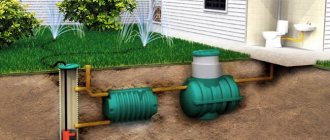
General concepts about drainage
Drainage in a dacha is a whole complex of various structures that are designed to drain water from residential and commercial buildings. To properly design and install a sewer system, you need to know what drainage systems exist, what they are intended for, and how they differ from each other.
Principles of classification of wastewater systems
All systems can be divided into three large types:
- Industrial sewerage (will not be considered in this case),
- Storm drainage,
- Household.
The latter is divided into two more types: centralized and autonomous. Centralized sewerage is installed in populated areas. But for private households, an autonomous drainage system is used.
In addition, sewerage is divided into internal and external. Internal includes all equipment for drainage that is installed indoors: plumbing, pipelines, filters. The external system consists of pipes, treatment facilities, and pumping stations (if any) installed outside.
External drainage (sewage) varies in design.
- General (all-alloy) sewerage . All types of wastewater (domestic, storm water) are disposed of together. The advantage of such a device is that it simplifies maintenance and also reduces the cost of constructing a drainage system.
- Separate sewerage . Domestic wastewater is disposed of separately from storm water.
- Semi-separate sewerage . The waters are discharged along different paths, but are ultimately combined in one collector.
For a summer residence, a semi-separate system is most often used. In this case, all domestic wastewater is removed through pipes, and stormwater mostly flows into drainage trays. Separate systems are less common. They are designed to collect storm water in separate containers and later use it either for domestic needs or for irrigation.
Description and principle of operation of drainage pipes
Drainage pipes can be made of asbestos cement, ceramics, metal, but they are rarely used due to their high cost, heavy weight and installation complexity.
Currently, corrugated perforated pipes made of polyvinyl chloride (PVC), high or low pressure polyethylene (LDPE or HDPE) are used to perform drainage systems.
Polymer pipes are lightweight, practical and durable. They are simple and easy to install, resistant to various fuels and chemicals.
Drainage pipes have a corrugated surface and perforation in the form of many holes with a diameter of one and a half to five millimeters located across the entire surface of the pipe.
Perforated pipes are available in various variations:
- single-layer;
- two-layer;
- with coconut fiber filter;
- in a geotextile shell.
Single-layer drainage pipes are used at a depth of no more than 1.5 meters. For greater trench depths, two-layer products are used.
Products with a filter and shell protect pipes from silting.
The diameter of the pipes is selected depending on the volume of water discharged.
Perforated drainage pipe.
Selection of drainage funnels
On the construction market, drainage funnels are presented in models made of galvanized steel, cast iron, PVC plastic, copper and other alloys.
Funnel designs are:
- bell-shaped, rising above the roof surface in the form of a dome-shaped lattice;
- flat, mounted flush with the roof surface;
- with vertical or horizontal outlet;
- with anti-gravel basket;
- heated by electric cable.
Figure 6. Construction of the ASO Spin rainwater inlet funnel.
The funnel design consists of the following parts:
- a supporting part mounted at the base of the covering;
- receiving element with pipe;
- upper section installed in insulating and waterproofing layers;
- an air filter, an o-ring and a pressure flange that hermetically connects the top of the funnel to the bottom;
- a grille that protects the drain from leaves and large debris;
- heating electric cable.
The most popular funnels for flat and pitched roofs, adapted to Russian climatic conditions, are offered by.
The products are manufactured by the Austrian company HuttererLechner, which produces HL brand funnels, and the largest German manufacturer of drainage systems, the ACO company.
The table shows the comparative characteristics of drainage funnels of the most popular models from.
| Brand | Purpose | Material | Type and diameter of outlet | Bandwidth Capacity (l/sec) | Construct. peculiarities |
| HL62.1 | for flat roofs | p/p | DN 110 Vertical release | 10,7 | with electric heating |
| HL64.1 | for flat roofs | p/p | DN 110 Horizontal release | 6,6 | with electric heating |
| HL64.1B | for exploitation roofs | p/p | DN 110 Horizontal release | 3,7 | without heating |
| HL62.1B | for exploitation roofs | p/p | DN 110 vertical outlet | 6,0 | with electrical heating and flange |
| ACO Spin | for flat roofs | stainless steel steel | DN 100 vertical outlet | 5,9 | with anti-gravel basket |
| ACO Spin | for flat roofs | stainless steel steel | DN 100 horizontal release | 5,9 | with thermal insulation |
| ACO Spin | for flat roofs | cast iron | DN 100 vertical outlet | 9 | with t/i, domed grille |
| ACO Spin | for flat insulation roofs | cast iron | DN 100 vertical outlet | 9 | with t/i, domed grille |
| ACO Spin | for exploitation roofs | cast iron | DN 100 vertical outlet | 8 | with p/w insert, cast iron grate |
All drains comply with state standards and safety requirements.
How to clear a clogged drain pipe?
Cleaning of drainage pipes can be done mechanically or hydrodynamically.
- Mechanical cleaning is carried out using various brushes, brushes or a sewer cable with a steel brush.
- Hydrodynamic cleaning is carried out using pumping equipment and a compressor. The blockage is cleared with a strong stream of water.
If you were unable to clear the blockage on your own, you should invite specialists who, using special equipment and pneumatic pumps, will clear the blockages and perform preventive maintenance of the entire drainage system.
Cleaning the drain.
Decorating drainage ditches
The installation of drainage systems should be carried out before the start of landscaping work on the site.
Drainage ditches must fit harmoniously into the natural landscape.
When designing a trench, it is worth taking into account the general style of the site, the slope of the terrain, the location of green spaces and the architectural style of existing buildings.
To decorate drainage ditches, the following are used:
- natural stones laid with cement mortar or dry masonry;
- decorative grilles and hatches made of metal, plastic or sand concrete;
- gabions or Reno mattresses, which are metal mesh filled with stones.
Drainage ditches can be made in the form of a natural stream, supplemented with bridges or artificial ponds.
Aquatic and moisture-loving plants are planted along the edges of the ditch.
An interesting solution in garden design would be the “French ditch”. It is a trench 50-70 centimeters deep, filled with crushed stone or gravel. This option is convenient because garbage does not accumulate in such a ditch and water does not “bloom.”
Drainage ditches can be installed along paths, fences, or to zone different areas of the garden.
Decoratively designed drainage can become a real decoration of a suburban area.
"French Ditch"
Filtration and storage wells
Drainage wells play an important role in the drainage system of the site.
There are tanks for various functional purposes, the main ones are:
Filtering
Designed for wastewater treatment. Wells are effective in areas where the volume of drainage does not exceed one or two cubic meters per day.
They are vertically installed cylindrical or cone-shaped containers, without a bottom, up to two meters deep.
Wells can be made of plastic or reinforced concrete rings.
At the base of the well, a filter layer of washed river sand, crushed stone, brick chips or coarse gravel, 20-30 cm thick, is poured and covered with geotextile.
The outside of the structure is also covered with crushed stone.
The wastewater enters through drainage pipes that enter the well at the top of the tank and goes through the drainage layer directly into the ground. Passing through a layer of sand and crushed stone, wastewater is purified from various contaminants.
Filter wells are installed at the lowest point of the site, no closer than 20 meters from the water intake well.
Filter wells are effective only on sandy and sandy loam soils that have good moisture absorption.
Installation of a filter well.
Cumulative
Wells are made of large-diameter plastic corrugated pipes, reinforced concrete or polymer-sand rings, steel or aluminum sealed tanks.
The bottom of the wells is concreted or the plastic bottom is sealed with bitumen.
Storage well made of reinforced concrete rings.
Drainage pipes cut into the installed tank. The joints are sealed hermetically.
Sand or crushed stone is poured between the tank and the walls of the pit.
The well is hermetically sealed with a metal, concrete or cast iron lid.
Water collected in a storage well can be used for technical purposes or for watering plants on the site.
Excess water is discharged into nearby ravines or reservoirs, in agreement with local authorities. To do this, a sewage conduit is installed through which the water can flow by gravity or be pumped out by a deep submersible pump.
The pump can be driven by a float sensor that responds to the fill level of the tank.
An effective and functional drainage ditch will ensure optimal humidity in the area.
Advice from the experts
Professional craftsmen have prepared several basic recommendations for installing drainage systems:
- It is necessary to plan work to drain water from the site after conducting geological surveys and examining the soil. If the area is waterlogged, drainage installation should be done before construction work begins.
- The design of drainage ditches should be selected taking into account the height of the snow cover, maximum precipitation level, freezing depth and groundwater level.
- It is better to use plastic perforated pipes to install drains. All connections must be made hermetically to protect the system from damage, leaks, and displacement as a result of frost heaving of the soil.
- When installing closed drainages, it is necessary to install inspection wells for cleaning and maintaining the system.
- Work on installing drainage ditches can be done independently, but it is better to entrust the geological survey of the site and drainage design to specialists.
For normal functioning of the drainage, the system should be cleaned and flushed from silt and sand at least once a year. Gutters and channels must be regularly cleared of leaves, branches, and large debris.
Project Creation Basics
Design is the initial stage in any work. This directly applies to the creation of a drainage system.
Wall drainage diagram.
When designing a drainage system, the following factors are taken into account:
- level of resistance of soil rocks to the process of washing out particles;
- permeability indicator of individual rocks;
- the presence of tectonic disturbances on the site;
- composition of groundwater;
- location of sources recharging groundwater and their intensity.
The drainage plan must comply with the provisions of current regulations. The main requirements are:
- the size of the slope from the top point of the pipeline to the drainage structures is 0.5-0.7%;
- the presence of elements that control the functioning of the system and flush it;
- the bottom of the pipe is located 20 cm below the foundation level (if the drainage is close to the house)
If possible, the plan should include the installation of inspection wells. They should be installed in places where the pipe turns.