Home gas line pressure
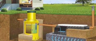
The nominal gas pressure for a home gas pipeline should be in the range of up to 2 mPa ÷ 1000 (artificial gas) – up to 3 mPa ÷ 1000 (natural gas) – up to 4 mPa ÷ 1000 (liquefied gas). Main gas pipelines can have a pressure of 0.1-0.6 MP. The gas pressure is reduced before it is supplied to the internal gas pipeline of the house using a house gas control point (DRP).
The DRP is mounted on the wall of the house in a cabinet or on the site in a cabinet raised on a fireproof platform, with a separate grounding.
Where to place it?
It is allowed to make a chimney for the boiler inside the house or outside. Both options have their advantages and disadvantages, shown in the table:
| Location | pros | Minuses |
| In the house | Part of the structure in the attic and roof is insulated | Fires and carbon monoxide leaks are more common |
| Outside the building | Safer to use | The entire pipe requires thermal insulation |
| Repair work is easy to do |
How to connect gas pipes
Preferably a welded connection of pipes for gas. Connection points for gas fittings can be connected with flanges and threads. The threads are sealed with flax, which is coated with red lead paint or lead white paint. A more modern seal is FUM tape (fluoroplastic sealing material).
When laying an internal gas pipeline, you will have to bend it. Bend radii are standard. When installing pipes up to Ø4 cm, the bending radius must be at least 2.5 times the pipe diameter. For pipes 4-5 cm, the bending radius is at least 3 times the diameter. Pipes of other diameters do not bend in the gas pipeline.
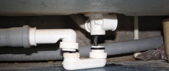
Flange connection of gas pipeline pipes
You can see the flange connection of the pipes in the photo. This connection requires gaskets. They are made from paronite. A flange connection is unlikely to be needed in the internal gas pipeline of a house, although it is possible in a DRP.
Connecting gas pipes by welding
The main connection of gas pipes in the house is welding. Any welding can be used:
- Electric arc welding by hand (electrodes No. 42, 42A, 46, 46A, 50A).
- Automatic welding with fluxes and wire Sv-08-A, Sv-08-GA.
The same wire is used in gas welding. In the internal gas pipeline of the house, you need to use fittings (valves, valves, taps) only designed for operation in a gas environment.
SEARCH
Heat losses to the atmosphere by the furnace masonry and returbents depend on the surface of the furnace, the thickness and material of the masonry and roof.
They make up 6-10%. Heat loss from the walls of the combustion chamber is estimated at 2-6%, and in the convection chamber within 3-4%. Heat losses from flue gases depend on the excess air coefficient and the temperature of the gases leaving the chimney. They can be identified from Fig. 177 (a and b), taking into account that the temperature of the flue gases during natural draft should not be lower than 250 ° C and 100-150 ° C higher than the temperature of the raw materials entering the furnace. By using the heat of exhaust flue gases to heat the air using artificial draft, it is possible to significantly reduce heat loss and have a tubular furnace with an efficiency of 0.83-0.88. [p.284] Temperature of the flue gases at the pass, i.e., the temperature of the flue gases entering the convection chamber. Usually this temperature is in the range of 700-900 ° C, although it can be lower. It is not recommended to increase the temperature of gases at the pass excessively, as this can cause coking and burnout of the radiant pipes. [p.104] And only by shielding the combustion chamber and increasing its volume were normal conditions created for the operation of the coil. Radiant-type tubular furnaces were created. In early designs of such furnaces, the ceiling screen pipes were protected from severe flame exposure by cuffs made of fire-resistant material. Corrugated cast iron cuffs on convection pipes increased the heating surface in the convection chamber of the furnace. As a result of shielding the furnace ceiling, heat transfer by radiation increased, the temperature of the flue gases above the pass decreased, and the need for protective cuffs and flue gas recirculation was eliminated. For maximum heat utilization [p.273]
Flue gas temperature after boiler - 210 210 — [p.219]
Technological design standards provide for a reduction in the temperature of flue gases before entering the chimney at natural draft to 250 °C. If you have special smoke exhausters, the temperature can be reduced to 180-200 °C. The heat of flue gases having a temperature of 200-450 ° C (average figure) can be used to heat air, water, oil in the installation and to produce water steam. Below are data on the thermal resources of flue gases at an ELOU-AVT installation with secondary distillation of gasoline with a capacity of 3 million tons/year of sulfur oil [p.211]
Average flue gas temperature of 293 305 310 - [p.219]
The temperature regime of raw material heat exchangers is also limited. The maximum permissible temperature at a regeneration pressure of 3.0-4.0 MPa should not exceed 425 ° C, and therefore the temperature of the flue gases leaving the reactors before entering the raw heat exchanger should be reduced by mixing with a cold coolant. [p.129]
Thermal intensity of pipes, kcal/(m2-h) radiant convection Flue gas temperature, [p.121]
Surface of heaters, Air heating temperature in heaters, °С Temperature of flue gases, °С [p.186]
Typically, the temperature of the flue gases at the pass is automatically regulated with correction based on the temperature of the product at the outlet of the furnace. To monitor and regulate tube furnaces, the following elements are provided in their piping. [p.48]
Liquid fuel consumption, kg/h Flue gas temperature at the furnace outlet, °C. . . . Flue gas volume at gas outlet temperature from 4000 3130 2200 [p.211]
Flue gas temperature in front of the boilers, °C 375 400 410 — [p.219]
In drying installations, the material being processed is not in close proximity to the furnace, as is the case in furnaces for various types of cooking, distillation and similar boilers. Therefore, the temperature in the combustion chamber of the drying installation can be significantly higher than the temperature in the furnaces, in in which the devices that consume heat are located. However, in this case, the temperature is determined by the properties of the material being dried and the requirements dictated by the quality of the product. Some types of raw materials do not tolerate high temperatures, so it is necessary to reduce the temperature of the flue gases to the temperature [p.252]
Based on the amount of heat given off by a given amount of flue gases in the radiation system, the temperature of the flue gases entering the convective system is determined. [p.269]
During operation of the regenerator, the flue gas temperature may exceed normal due to the combustion of carbon monoxide. If this phenomenon is detected in a timely manner, it is necessary to redistribute the air across sections, reducing the supply to those sections where there is excess oxygen in the flue gases leaving the section, and increasing its supply to sections where there is not enough oxygen. In the event of a sharp increase in the temperature of the exhaust gases, the air supply to individual or all sections is temporarily stopped. [p.153]
Primary reforming of natural gas with steam is carried out in vertically located pipes heated by flue gases, the lower ends of which are introduced directly into the secondary methane reforming reactor. A portion of the flue gases is fed through a perforated plate into the secondary reforming catalyst bed, which produces nitrogen-enriched gas. Flue gas temperature - 815° C [p.97]
Fire-type stoves have been replaced by convection stoves, in which the pipe coil is separated from the combustion chamber by a pass wall. During the operation of such furnaces, significant disadvantages were identified: high temperature of the flue gases above the pass wall, melting and deformation of the brickwork, burnout of the pipes of the upper rows of the coil. To reduce the temperature in the combustion chamber, flue gas recirculation was used and fuel was burned with an increased excess air ratio. However, increased air flow reduced the efficiency of the furnaces and did not reduce pipe burnout. [p.273]
Temperature at the superheater. In some cases, a coil is installed in the convection section of the furnace to superheat water vapor supplied to distillation columns for stripping low-boiling fractions. The superheater is placed where the temperature of the flue gases is 450-550 ° C, i.e. in the middle or lower section of the convection chamber. The temperature of superheated steam is 350-400° C. [p.282]
The temperature of the flue gases above the pass wall is especially important. The high temperature of gases at the pass corresponds to high thermal stress on the surface of the radiant tubes, the temperature of their walls and a high probability of coke formation. Being deposited on the inner surface of the pipes, coke impedes heat transfer, which leads to a further increase in the temperature of the walls and to their burnout. [p.283]
Increasing the speed of movement of the heated raw material in the furnace pipes increases the efficiency of heat removal, reduces the temperature of the pipe walls and, thus, makes it possible to work with higher thermal intensity of the radiant pipes and the temperature of the flue gases at the pass. [p.283]
A typical ELOU-AVT (A-12/9) installation with a capacity of 3 million tons/year with secondary distillation of gasoline has five furnaces with a total thermal capacity of 81 Gkcal/h. In all furnaces, 11,130 kg of fuel are burned in 1 hour. The temperature of the flue gases at the exit from the convection chambers of the furnaces is 375–410 °C. To use the thermal energy of flue gases before entering them into the chimney, remote waste heat boilers of the KU-40 type are installed in the furnaces. [p.219]
The lower the temperature of the flue gases leaving the convection chamber, the more heat is absorbed by the heated oil product. Typically, the temperature of the flue gases at the exit from the convection chamber is taken to be 100-150 ° C higher than the temperature of the raw materials entering the furnace. But since the temperature of the raw materials entering the furnace can be quite high, approximately 160-200 ° C, and for some processes reaches 250-300 ° C, then to utilize the heat of the flue gases, an air heater (recuperator) is installed, in which the air going into the furnace is heated ovens. If there is an air heater and a smoke exhauster, it is possible to cool the flue gases before releasing them into the chimney to a temperature of 150° C. With natural draft, this temperature is at least 250° C. [p.90]
Convection pipes receive heat through convection of flue gases, radiation from masonry walls and radiation of triatomic gases. As noted at the beginning of the chapter, heat transfer in a convection chamber depends on the velocity and temperature of the flue gases, as well as the temperature of the feedstock, the diameter of the pipes and their arrangement. The speed of flue gases in a convection shaft usually varies between 3-4 m/sec, and in a chimney 4-6 m/sec. [p.107]
Solution. Let us determine the efficiency of the furnace if the temperature of the flue gases at the exit from the convection chamber [p.113]
The temperature of the flue gases at the outlet of the furnace is 500 C. The heat of the flue gases is utilized in a tubular three-pass (via air) air heater with a heating surface of 875 m2. After the air heater, flue gases at 250 C are removed into the atmosphere through a chimney without the use of forced drafts. [p.107]
Let us set the temperature of the flue gases after the heating section of the radiation chamber to g, c = 850° C, and after the reaction section ip. c = 750° C. Heat content of flue gases but fig. 6. 1 at a = 1.1 [p.120]
A distinctive feature of waste heat boilers, as equipment for generating steam, is the need to ensure the passage of a large amount of heating flue gases per unit of generated water steam (E1/d.g/C). This ratio is a direct function of the initial temperature of the flue gases at the entrance to the apparatus and their flow rate. Due to the relatively low temperature of the flue gases for generating steam, their specific consumption in waste heat boilers is much higher (8-10 times) than in conventional combustion boilers. The increased specific consumption of heating gases per unit of generated steam predetermines the design features of waste heat boilers. They have large dimensions and high metal consumption. To overcome additional gas-dynamic resistance and create the required vacuum in the furnace firebox (draft), 10-15% of the equivalent electrical power of the waste heat boiler is spent. [p.76]
Having filled the hopper with dried catalyst, open the valve under the hopper and pour the catalyst into the calcination column. The volume of the hopper corresponds to the useful volume of the calcination column, i.e. one load. Having filled the column with a catalyst, the furnace is ignited under pressure (using liquid fuel), directing the flue gases into the atmosphere. Then, having adjusted the combustion in the furnace, the flue gases are introduced into the casing of the calcination column. After heating the casing and making sure that the fuel is burning normally, the flue gases are directed to the bottom of the calcination column in the minimum amount necessary only to overcome the resistance of the catalyst layer. Then they begin to slowly raise the temperature of the flue gases at the exit from the furnace and warm up the catalyst. Warming up of the system continues for approximately 10-12 hours, during which time such an amount of flue gases is introduced so that there is no carryover of the catalyst from above. Reaching a temperature at the bottom of the column of 600-650° C is considered the beginning of catalyst calcination. The duration of calcination at this temperature is 10 hours. [p.68]
Then they gradually lower the temperature of the flue gases at the exit from the furnace and at 250-300 ° C they stop supplying fuel, but [p.68]
The temperature of the gases at the pass, the thermal tension of the heating surface of the radiant tubes and the direct efficiency coefficient of the furnace are mutually related. The higher the direct return coefficient, the lower, other things being equal, the temperature of the flue gases at the point of maturity and the lower the thermal tension of the heating surface of the radiant pipes and vice versa. [p.105]
Tubular coil reactors. A tubular coil reactor with a vertical arrangement of pipes was developed for the production of bitumen in a continuous manner at domestic refineries [2, 55, 190]. Temperature conditions of reactors. (Kremenchug and Novogorkovsky refineries) is maintained by the heat of flue gases coming from the prechamber furnace. However, this solution does not take into account the specifics of the exothermic oxidation process. Indeed, to accelerate the heating of the reaction mixture in the first reactor pipes along the flow, it is necessary to increase the temperature of the flue gases, but as a result, the oxidized material in subsequent pipes is overheated, where the oxidation reaction and heat release occur at high rates. Thus, it is necessary to maintain some intermediate temperature of the flue gases, neo[tpmal y, both to heat the reaction mixture to the reaction temperature, and to subsequently maintain the temperature at the desired level. For the installations of the Angarsk, Kirishi, Polotsk, Novoyaroslavl and Syzran refineries, a more successful solution has been found: the raw materials are preheated in a tube furnace, and excess reaction heat, if necessary, is removed by blowing air through the reactor pipes placed in a common casing (according to the design of the Omsk branch of VNIPIneft, each reactor pipe placed in a separate casing). [p.130]
If the temperature of the flue gases at the exit from the common collecting manifolds of the regenerator exceeds 650°, this indicates the beginning of carbon monoxide afterburning. To stop it, it is necessary to sharply reduce the air supply to the upper part of the regenerator. [p.145]
In order to reduce the temperature of the flue gases above the pass wall, in old-style radipant-convection furnaces, especially thermal cracking furnaces, flue gas recirculation is used. Cooler flue gases from the furnace hog are returned to the combustion chamber, which leads to heat redistribution between the chambers. In the convection chamber, the thermal tension of the upper pipes is reduced, but due to the increase in the volume of flue gases, their speed increases, and heat transfer throughout the convection chamber improves. The recirculation coefficient in tube furnaces ranges from 1 to 3. [p.90]
The imperfect design of the burners of furnaces and boilers for burning fuel and the insufficient sealing of the furnaces do not yet allow operation with small excess air. Therefore, it is believed that the temperature of the air heater tubes should be higher than the dew point temperature of aggressive flue gases, i.e. not lower than 130 °C. For this purpose, preliminary or intermediate heating of cold air or special heating surface layout schemes are used. There are devices that are structurally designed in such a way that the heat exchange surface on the flue gas side is much larger than on the atmospheric air side, so air heater sections are assembled from pipes with different finning coefficients, increasing towards the cold end (to the point of entry of cold air), and thus the temperature the pipe walls approach the temperature of the flue gases. Bashorgener-Goneft air heaters are constructed using this principle from cast-iron finned and ribbed-toothed pipes with good performance indicators. [p.80]
The catalyst is heated and calcined by direct contact with flue gases coming from the furnace in which gaseous or liquid fuel is burned. The temperature of the flue gases is automatically maintained at the level of 630-650 ° C, while the temperature in the calcination zone is 600-630 ° C. The calcined catalyst enters the cooling chon through the iridescent tubes of the lower grille-gate, where it moves between rows of air-cooled pipes and It cools itself to the desired temperature. A movable metal cup is placed at the end of the refining tube, the position of which regulates the height of the catalyst layer on the conveyor located below and, consequently, the speed of product unloading. A conveyor belt feeds the unloaded catalyst into a screen for screening out fines. Next, it is poured into metal barrels and delivered to the finished product warehouse. [p.70]
The higher the temperature of the heated raw material in the radiant tubes and the greater its tendency to coke formation, the lower the thermal intensity should be, and therefore, the lower the temperature of the flue gases above the pass. For this furnace, an increase in the surface of the radiant tubes leads to a decrease in the temperature of the flue gases above the pass and the heat intensity of the radiant tubes. Contamination of the inner surface of the pipes with coke or other deposits can lead to an increase in the temperature of the flue gases above the pass and to burnout of the first rows of pipes in the convection chamber of the furnace. The temperature over the pass is carefully controlled and usually does not exceed 850-900° C. [p.283]
The temperature of the flue gases above the pass wall is usually maintained at 700-850 ° C, i.e., high enough to transfer part of the heat by radiation to the upper rows of pipes of the convection chamber. But the main amount of heat in the convection chamber is transferred due to forced convection of flue gases (created by a chimney or smoke exhauster). [p.89]
The fraction of distillate at the furnace outlet is e = 0.4, the density of distillate vapor = 0.86. residue density = 0.910. The diameter of the pipes in the radiation chamber is 152 X 6 mm, in the convection chamber 127 X 6 mm, the useful length of the pipes is 11.5 m, the number of pipes is 90 and 120 pieces, respectively. The fuel composition and theoretical air flow are the same as in examples 6. 1 and 6. 2, the heat content of flue gases with excess air a = 1.4 can be found from Fig. 6. 1. Flue gas temperature at the pass [p.109]
The total duration of hydrothermal treatment including heating is approximately one day. After the pressure in the apparatus begins to drop, the temperature of the flue gases at the outlet of the furnace is gradually reduced and, finally, the nozzle is extinguished. The apparatus is cooled with cold air from the firebox through the casing. The dried balls are unloaded and sent to the hopper of the calcination column. [p.127]
Suction pyrometers. In the practice of measuring high flue gas temperatures, suction pyrometers are used. The main elements of suction pyrometers are a thermocouple placed in a cooled housing, a screen system and a device for suctioning gases. Thermal electrodes are insulated from one another and from the protective cover by rigid elements (straw tubes, single- and double-channel beads) made of quartz (up to 1100°C), porcelain (up to 1200°C), and porcelain with a high alumina content (up to 1350°C ) ceramic materials and glass enamels applied by broaching methods. [p.139]
When the niroscoils become coked, there is a gradual increase in the temperature of the pipe wall, the pressure drop increases, and white spots may be observed in places where the pipes are overheated. The formation of coke deposits in the pyro-coils is also judged by the increase in the temperature of the flue gases at the furnace pass. Coking of the IIA is characterized by an increase in the hydraulic resistance of the system with an increase in the temperature of the pyrolysis products after the IIA. An increase in hydraulic resistance in pyro-coils and ZIA is accompanied by an increase in pressure in the furnace unit and, as a result, the contact time increases and the yield of lower olefins decreases. [p.198]
chem21.info
Preparation for installation work
Before installing the systems, you need to complete the following preparatory work:
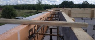
- Make passage holes for pipes (walls, floors, foundations) for laying gas pipeline pipes;
- If you plan to hide a gas pipeline, you need to prepare grooves for it;
- The floors where gas equipment will be placed must be ready;
- When installing equipment on the wall, the walls are plastered;
- Plumbing and equipment to which gas and hot water will be supplied must remain in place.
Why gasify housing?
Today, natural gas is the most convenient and, importantly, profitable type of fuel. Sooner or later, every owner of a private house will want to gasify their property. Of course, there is an alternative - electricity. However, its cost is too high and it is very expensive to heat large areas in winter in this way. Plus, you will always depend on weather conditions - any hurricane can cause a break in the cables and then you will have to be left for some time without food, hot water and heating. But damaging a gas line is much more difficult.
Photo of natural gas
There is, of course, another “grandmother’s” way to heat your home - a stove or fireplace. But ash, coal, firewood, all this will lead to excess dirt. Lighting a stove takes a lot of time and labor, so it's best left as an option in case of an apocalypse. So, whatever one may say, blue fuel occupies a leading position today.
Installation rules
Gas pipes are connected by welding;
- Control, shutdown, and regulating devices are connected with threads or flanges. Distortions in connections are unacceptable;
- Pipe joints cannot be hidden in a groove or box;
- Connections require direct access;
- The pipes need to be painted;
- When closing the pipes with a box, gas. pipes to the box should be at least 10-11 cm;
- 10-15 cm should separate the weld from the passage through the wall and base of the house;
- For convenient installation and dismantling of taps, inlets, branches, you need to install squeegees with lock nuts;
- Usually, the distance from gas pipes to the walls of the house is indicated in the house gasification project. If this is not the case, a distance of at least the diameter of the gas pipe is taken.
Use of wood based on its heat capacity
When choosing a type of firewood, it is worth considering the ratio of cost and heat capacity of a particular wood. As practice shows, the best option can be considered birch firewood, which has the best balance of these indicators. If you purchase more expensive firewood, the costs will be less effective.
To heat a house with a solid fuel boiler, it is not recommended to use types of wood such as spruce, pine or fir. The fact is that in this case, the combustion temperature of the wood in the boiler will not be high enough, and a lot of soot will accumulate on the chimneys.
Firewood made from alder, aspen, linden and poplar also has low thermal efficiency due to its porous structure. In addition, sometimes during the burning process alder and some other types of firewood shoot out coals. In the case of an open furnace, such micro-explosions can lead to fires.
It is worth noting that no matter what the wood is, if it is damp, it burns worse than dry wood and does not burn completely, leaving a lot of ash.
Laying a gas pipeline
Let's look at the permitted minimum distances from the gas pipeline to other communications.
- From the surface of the gas pipe to the open wiring there should be 25 cm when laying parallel and 10 cm when intersecting;
- For hidden wiring, these distances are reduced to 5 cm and 1 cm, respectively. The same rule applies to wiring in pipes;
- Distribution and input panels with gas pipes should not intersect;
- There must be a distance of at least 1000 mm to the “bare” electrical wiring busbars;
- Utilities (water, sewerage) intersect with the gas pipeline no closer than 2 cm. Parallel installation is selected locally and is not standardized.
Service
How to clean such a chimney?
To clean a horizontal chimney, it is necessary to provide either special doors or areas with knockout bricks. Without these technological holes, it is impossible to clean the snake chimney.
Craftsmen advise periodically heating the stoves with dry aspen firewood and potato peelings.
These methods are not a panacea, but a good way to prevent soot formation.
Installation of gas consumers at home
- The gas water heater is installed 2 cm from a fireproof wall and 3 cm from a fire-resistant wall. The walls are insulated with a “sandwich” of 3 mm asbestos and roofing steel. The insulator must be 100 mm larger than the dimensions of the water heater on each side.
- A tiled wall does not require additional protection.
- The wood is plastered over a grid. Next, they are covered with asbestos or asbestos plywood, and covered with roofing steel.
- The wall where the stove stands is closed from the floor. The distance from the slab to the wall is taken to be 70 mm.
Design features
Heating of the room from a wood-burning stove is carried out by heating the brickwork of the stove during combustion. The burning interval of firewood is short, so it is important to use the generated thermal energy as efficiently as possible.
Horizontal wells in the chimney of a brick stove enhance the heat transfer of combustion products. If the vertical chimney has minimal contact with gases and smoke, then the horizontal sections slow down their removal, forcing them to come into contact with a large area. The stronger the draft of the smoke exhaust channel, the more intense the fuel burns. The slower the smoke passes through the chimney, the more heat remains in the room.
Note! A well-chosen diameter and configuration of the chimney allows you to find a balance between the draft force and the level of heat transfer.
The design of the horizontal chimney is a vertical snake. Each turn is called a revolution, and the chimney itself is called multi-turn. The passage of smoke through such a coil should be as free as possible so that the effect of smoke being sucked back into the room does not occur.
Design features of a horizontal chimney:
- the channels are built the same size throughout;
- horizontal sections have a length of up to 1 m;
- the total length of horizontal channels should not exceed 3 meters;
- horizontal sections have a small angle of elevation in the direction of smoke exhaust;
- on turns, corners are made rounded so as not to provoke the formation of gas vortices;
- the inner walls must be smooth; protrusions and irregularities are not allowed.
It should be understood that it is better to entrust the construction of an effective and safe chimney to professionals. To install a horizontal chimney, you will need a competent engineering design that takes into account the features of the internal design and the correct external outlet of the chimney. This takes into account the height of the pipe, its location relative to the roof ridge, and even nearby tall buildings or trees.
Delivery and acceptance of internal gas supply systems
- Hidden work is accepted during the installation process;
- The finished gas pipeline is tested by contractors together with the customer and the distribution network of the Oblgaz branch. The results are recorded in the construction passport or in a separate act.
- The gas pipeline is checked with air under pressure.
Water testing is prohibited.
- Checking for defects in connections is carried out with pressure: 100,000 Pa;
- Checking the density of connections by pressure: 4000 Pa with a meter and 5000 Pa without a meter.
- Tests are carried out with the devices turned on. The gas pipeline is in good condition for tight connections if the pressure in the pipes drops by no more than 200 Pa in 5 minutes.
Based on the tests, a report is drawn up. The act is signed by the installation organization and the district distribution network. According to this act, the acceptance committee consisting of: the customer, the installation organization, the Distribution Zone and Technical Supervision gives permission to start the gas. Gas is released into the house by the repair and maintenance service of the district, in the presence of the organization that did the installation. Next, the system is accepted into operation according to the act. Acceptance of the gas supply system for operation is formalized by an act.
©Obotoplenii.ru.
Other articles in the section Gasification at home
- Construction and installation of internal gas supply at home
- What is a gas regulatory point
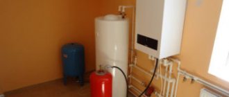
- Requirements for a room with a gas boiler
- Installation of a gas boiler in a house: stage of gasification of a private house
- Brick chimney for gas boiler
- Stages of gasification at home
- Chimney for a gas boiler: description, height, installation
Popular articles
Types of chimneys for boilers
There are different types of chimneys that are used in these cases:
A brick chimney is made of fireclay bricks, which are placed either on clay mortar or glue. In most cases, it is made with a stainless or galvanized steel sleeve inside to protect the brick from the destructive effects of carbon dioxide.
Region190FORUMHOUSE participant, master inspector at VDPO
Over time, the brick will begin to crumble due to carbon dioxide, so the chimney must be lined. In the market you can be deceived with the steel grade; it is better to buy AISI 316 directly from the factory. This acid-resistant steel works reliably with any brand of boiler. Not a single inspection master will ask you about the steel grade or demand a certificate; we do not have the authority to do this, and it is impossible to visually distinguish 316 from 425.
The main disadvantage of such a chimney is that it is heavy, you will have to make an additional foundation, and it is bulky, and you will have to look for a stove maker who will lay it out. Previously, such chimneys were often made for gas boilers; now (if funds allow) homeowners prefer ceramics.
Ceramic chimney . This is a complex structure that includes a ceramic smoke exhaust duct, an air layer (or insulation) and an expanded clay concrete shell. Expanded clay concrete protects the fragile ceramic pipe and serves as insulation (and ceramics have high thermal conductivity).
Andrey50FORUMHOUSE member
Cool specialists with extensive experience in chimneys say that ceramics are the best, but unreasonably expensive.
It is much easier to install such a structure than a brick chimney; it is durable, fireproof (can heat up to 120 degrees), but it is also heavy and bulky, and also expensive.
Asbestos-cement chimney. For this type, it is important to have tight joints inside the channels and good insulation to prevent condensation from forming.
RegularUser .FORUMHOUSE
During my construction period, asbestos-cement pipe was the cheapest option. The main problem here is how to hermetically join the segments; I couldn’t get it to be hermetically sealed. Simply pouring concrete is not an option. It should be a sealed sleeve, clamp, insert, anything that provides a reliable and tight connection. Be sure to insulate your asbestos-cement pipes. Do not forget that the design of the chimney should not allow condensate to drain into the boiler and be sure to make a condensate collector at the bottom at the base of the pipe.
Single metal - chimney made of galvanized or stainless steel.
Sandwich chimney. Such a chimney is made of two metal pipes, one is inserted into the other, and insulation is laid between them. Smoke flows through the inner cylinder. This type is required for use as an external chimney and in unheated rooms.
Coaxial. In this chimney, one pipe is inserted into another without laying insulation. But this is a single rigid structure, united by jumpers along its entire length. Smoke exits through the inner pipe, and air enters the combustion chamber through the outer pipe; the room air does not participate in the operation of the gas boiler, the microclimate is maintained.
Mr LeshiyFORUMHOUSE Member
Sandwich is an insulated chimney made of two stainless steel cylinders, between which insulation is stuffed. Coaxial - the same two cylinders, but without insulation inside. Exhaust gases are removed through the inner cylinder to the outside, and air is supplied into the combustion chamber through the gap between the cylinders.
Gas pipe on the site: what restrictions exist for the security zone?
Certain restrictions are imposed on the territory that is located within the security zone. Let's look at them:
Important! The destruction of benchmarks and other signs located on communications is strictly prohibited.
For gas pipeline structures that are in the process of being laid, approval of such zones is carried out in the presence of the owner of the site. For existing gas transmission lines, the presence of the owner of the land plot is not mandatory.
Source
Make it yourself or order it
Order a chimney from professionals or do it yourself – it’s up to you.
Proper independent installation of a smoke exhaust system will definitely save the family budget. When installing, be sure to comply with all requirements of SNiP and fire regulations.
Despite the fact that the temperature of the exhaust gases is low, the harm from them is no less than from any other emissions. Therefore, special attention should be paid to the tightness of joints.
It is also mandatory to organize a condensate collection system.