Grounding in a private home is a problem that needs to be solved first. Grounding solves the problem of protecting consumers from the damaging effects of electric current. If the insulation of wires and devices is faulty, current flows through grounding.
In this case, the protection device (RCD) is triggered and the voltage is cut off.
Grounding works fully if installed correctly and in compliance with all norms, rules and requirements of regulatory documents. When performing installation yourself, you should remember this and strictly follow these requirements.
Another function of grounding is the proper operation of electrical appliances. Some of them require a direct connection to ground, even if it is in the outlet. That’s why appliances have a special bolt (electric oven, washing machine, microwave).
When touching household appliances with wet hands, you often feel a slight tingling sensation. It is not dangerous, and you can get rid of it by connecting the ground directly to the case.
Do you need a grounding device when building your house?
The essence of grounding is that it is a device that directs electric current when electrical devices malfunction and are shorted to the housing along the path of least resistance to the ground.
Ground bus connection for entry into the house
Therefore, all current is directed to the ground loop and does not pose a danger when a person touches dangerous devices or wires.
The mandatory use of grounding for any private residential building is determined by the rules and regulations (PUE, GOSTs, SNIP).
Another purpose of the grounding system: increases the durability and reliability of household appliances. It protects against network interference, overvoltage and sources of electromagnetic radiation.
Errors when installing memory
Typical disadvantages often encountered in practice include:
- Use as a contour of metal fences or masts. Current resistance is not taken into account and creates the risk of severe electric shock to people in the event of an accident in the system.
- Connecting the circuit directly to the housing of electrical appliances, bypassing the grounding bars in the panel.
- Installation of separate switches in the neutral conductor. If the device fails, electrical appliances may become energized. Sometimes the neutral wire contact is not strong. The consequences are the same.
- Use of products of smaller cross-section or thickness for grounding conductors. Such electrodes quickly fail under the influence of corrosion.
- Use as a grounding conductor for the working “zero”. There is an increased likelihood that the system will be energized.
- Location of horizontal grounding conductors on the surface of the earth. In the event of an accident, the affected area will increase.
- Ground connection to the heating pipe. It is impossible to say which direction the stray currents will take, since the situation in the neighboring apartment is unknown. The likelihood of electric shock to strangers increases.
Upon completion of installation work, the system is checked. Attention is drawn to the value of current dissipation resistance. To carry out this work, it is advisable to involve a specialist with the appropriate equipment.
Grounding systems. Which one is better to use?
There are six such systems, but in our reality, as a rule, two are used: TN-SC and TT. Consider TN-SC, this circuit provides that the neutral wire (N) at the substation is grounded. In this case, earth (PE) and zero (N) are supplied to a private household by one wire (PEN) and then at the consumer’s electrical panel they are divided again into two.
TN-SC grounding schemes for a private house
In the case of using such a grounding scheme, the presence of automatic circuit breakers is sufficient for protection; an RCD is not necessary. But, you should know that when the PEN wire to the household breaks, a phase voltage appears on the ground bus in the house. According to the PUE rules, PEN wire protection and grounding on poles are required after 100 or 200 meters.
Due to long-term use and wear and tear, most power lines do not meet these requirements. Therefore, it is recommended to use the TT system. In this scheme, the PE wire goes to the panel from the ground loop, and not from the substation (TN-SC scheme). In this system, the protective wire is more protected, but it is necessary to use an RCD or a circuit breaker. Without them, protection is not provided; their use is mandatory.
TT grounding diagram for a private house
PUE 7, clause 1.7.59 states that if the electrical safety conditions in the TN system cannot be ensured (i.e. the main line is in such a deplorable state that it cannot ensure the reliability of the PEN conductor), then only then is it allowed to be grounded according to the scheme TT.
Main ground bus
According to clause 1.7.121 of the PUE, the following can be used as PE conductors in electrical installations with voltage up to 1 kV:
- specially provided conductors:
- cores of multi-core cables;
- insulated or non-insulated wires in a common sheath with phase wires;
- permanently laid insulated or non-insulated conductors;
- exposed conductive parts of electrical installations:
- aluminum cable sheaths;
- steel pipes for electrical wiring;
- metal shells and supporting structures of busbars and complete devices of factory production (provided that the design of the boxes and trays provides for such use, as indicated in the manufacturer’s documentation, and their location excludes the possibility of mechanical damage);
- Some third party conductive parts:
- metal building structures of buildings and structures (trusses, columns, etc.);
- reinforcement of reinforced concrete building structures, subject to the requirements of 1.7.122;
- metal structures for industrial purposes (crane rails, galleries, platforms, elevator shafts, lifts, elevators, channel frames, etc.).
P. 1.7.122. The use of exposed and third-party conductive parts as PE conductors is permitted if they meet the requirements of this chapter for conductivity and continuity of the electrical circuit.
More details
Third-party conductive parts can be used as PE conductors if they also simultaneously meet the following requirements:
- the continuity of the electrical circuit is ensured either by their design or by appropriate connections protected from mechanical, chemical and other damage;
- their dismantling is impossible unless measures are taken to maintain the continuity of the circuit and its conductivity.
The following are not allowed to be used as PE conductors:
- metal shells of insulating tubes and tubular wires, supporting cables for cable wiring, metal hoses, as well as lead sheaths of wires and cables;
- gas supply pipelines and other pipelines of flammable and explosive substances and mixtures, sewerage and central heating pipes;
- water pipes with insulating inserts.
Neutral protective conductors of circuits are not allowed to be used as neutral protective conductors of electrical equipment powered by other circuits, and also to use open conductive parts of electrical equipment as neutral protective conductors for other electrical equipment, with the exception of shells and supporting structures of busbars and complete factory-made devices that provide the possibility connecting protective conductors to them in the right place.
The use of specially designed protective conductors for other purposes is not permitted.
The main grounding bus can be made inside the input device of an electrical installation with voltage up to 1 kV or separately from it (clause 1.7.119. PUE).
Inside the input device, a PE bus should be used as the main grounding bus.
When installed separately, the main grounding bus must be located in an accessible, convenient place for maintenance near the input device.
The cross-section of a separately installed main grounding bus must be no less than the cross-section of the PE (PEN) conductor of the supply line.
The main grounding bus should, as a rule, be copper. It is allowed to use a main grounding bus made of steel. The use of aluminum tires is not permitted.
The design of the bus must provide for the possibility of individual disconnection of the conductors connected to it. Disconnection must only be possible using a tool.
Third-party conductive parts may be used to connect multiple main ground bars if they meet the electrical continuity and conductivity requirements of 1.7.122.
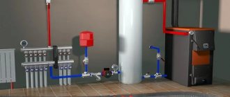
What is a ground loop: definition and device
A ground loop is an electrical device with low electrical resistance that allows you to quickly drain electric current into the ground. It consists of two parts connected to each other - an external and internal system. The connection of these parts is carried out in the electrical panel located at the entrance to the house.
The external system is a device that allows electric current to pass into the ground and then distribute it over an area. It usually consists of several electrodes driven (buried) into the ground and connected by welding with plates of a certain cross-section. From them, the welded tire extends into the shield, where it is connected to the inner part.
Grounding installation in a private house
What is an internal subsystem? This is the distribution of grounding wiring throughout all rooms and areas of the house to sockets and to powerful electrical installations. A common bus is formed, which is connected to the external circuit in the electrical panel.
The protective properties of grounding are very simple. If the insulation of the wires is broken, the current from the electrical network through the wires of the internal system enters the external ground loop. It flows into the ground along the electrodes of this circuit. It is known from electrical engineering that the earth has a large electrical capacity, which gives confidence in the absorption of such electrical leaks.
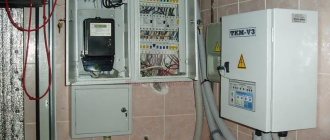
Installation of a box for an input circuit breaker
In order to prevent unauthorized connection, bypassing the electric meter, all switching and protective devices located before it must be closed in boxes (No. 2 in the image) and sealed.
So, during installation, we first install a special housing for the AB (circuit breaker). It differs in that it has “ears” for easy filling. In a three-phase 380V network, the box is installed on at least three modules so that the Circuit Breaker fits there.
Types of ground loops
For the grounding system to operate effectively, it must distribute the current “draining” into the ground over several electrodes that increase the dissipation area. There are two main types of grounding systems.
Ground loop - triangle
This type of circuit uses three pins, which are welded using strips into a triangle with equal sides. The length between the electrodes is selected depending on the length of the electrode penetration to two such depths. Those. for an electrode length (depth) of 2m, the side of the triangle will be 2-4m.
Ground loop - triangle
Linear
If it is impossible to make a closed figure due to the configuration of the area, a variant of several electrodes is made, they are placed in a semicircle or in a line. The gap between the driven pins should be 1-1.5 times the immersion depth of the pins. The disadvantage of this method is the large number of electrodes.
Ground loop - linear
The proposed types are the most used in the design and installation of grounding systems. It can be made in the form of any geometric figure (rectangle, circle, etc.), but you must understand that this will require an appropriate number of grounding pins. The main advantage of such systems is that if the connection between the electrodes is broken, the functions of the grounding system are preserved.
Important!
The linear circuit operates on the principle of a garland and damage to the jumper puts a certain section of it out of service.
Installation of accounting and security devices in the panel
Now it’s time to install all the other elements on the DIN rail. The complete list of equipment required for the panel of a private house is as follows:
1) Steel electrical panel (protection rating IP54 or higher)
2) Box/casing for AV for 3 modules
3) Three-pole circuit breaker 25A
4) Three-phase electric energy meter 380V
5) distribution block for DIN rail
6) Selective RCD from 40A, leakage current 100mA or 300mA
The electricity meter must be three-phase, for 380V networks. Usually electronic, two-tariff is chosen. When choosing a manufacturer, the main guideline is the warranty period; the one with the longest warranty should be taken. Usually a simple one is taken, without unnecessary interfaces, for example, Mercury or Energomera.
The distribution block must have a sufficient number of terminals for the required conductor cross-sections. For the option with a VDT - residual current switch, with CT grounding, you will need:
1 terminal – 16mm.kv – for re-grounding circuit PV1 or PuV (PuGV)
2 terminals of 6mm.kv - for internal conductors used for switching
The fire protection RCD is selected selective - having a delay when triggered. The leakage current can be either 100mA or 300mA.
The choice of the response threshold of the Residual Current Device depends on many factors. Almost any electrical appliance has some leakage and this is normal. If there are many such devices, the total losses can be large.
Based on this, this value is selected. If the housing is small, it is enough to set 100mA. If this is a cottage, with a lot of technology and equipment, then definitely 300mA.
For internal connections in the panel, it is most convenient to use flexible wires PuGV (also called PV-3) 1x6mm.sq. and NShVI tips.
Ground loop requirements
For effective operation of grounding according to the PUE, it must comply with the rules:
- Grounding pins welded into a circuit must be located at least 1 meter and no more than 10 meters from the house. The most correct distance from the foundation is 2-4 meters.
- The rods must be driven to a depth of 2-3 meters.
- The electrodes are connected using a metal strip using welding. A bus of more than 16 square millimeters is used from the shield to the ground loop. To connect wires to grounding in the shield, it can be done using bolts.
- The grounding resistance for a voltage of 380 volts should be no higher than 4 ohms, and for a voltage of 220 volts - 8 ohms.
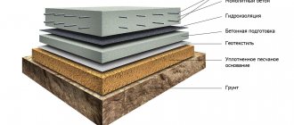
The external part of the grounding system is buried in the ground, so certain requirements are imposed on it. It must be below the freezing point of the soil, otherwise the electrodes will be pushed out due to swelling of the earth. The electrodes must be such that they can be driven into solid ground.
Recommended types and parameters of driven electrodes:
- corner metal thickness of at least 4 mm, any size;
- a pipe with a diameter convenient for driving, with a wall thickness of at least 3 mm;
- a rod with a diameter of at least 14 mm, a smaller one bends when immersed in the ground;
- strip for connecting electrodes, at least 3 mm thick and more than 10 mm wide.
The minimum length of the electrodes is chosen to be 1.5 meters, the pins are located at a distance of 1-2 lengths of the electrode. It should be taken into account that the electrodes (their length) should be 15-20 centimeters below the soil freezing level.
The main elements of the grounding connection diagram for a country house and the rules for their implementation
The grounding connection diagram in a country house is as follows: electrical appliance - socket - electrical panel - grounding conductor - ground loop - ground.
The connection begins with the installation of a grounding device in the local area in accordance with the rules defined in Chapter 1.7 of the PUE, 7th edition. The ground electrode is a metal structure that has a large contact area with the ground. Designed to equalize the potential difference and reduce the potential of grounded equipment in the event of a short circuit to the housing or the appearance of excess voltage in the electrical network. The design and depth of its installation is determined based on the soil resistance in the area (for example, dry sand or wet black soil).
From the grounding device (grounding) made on the site, we lay a grounding conductor, which is connected to the main grounding bus using a bolted connection, clamp or welding. We select a conductor with a cross-section of at least 6 mm2 for copper and 50 mm2 for steel, and it must meet the requirements for protective conductors specified in Table 54.2 of GOST R 50571.5.54-2013, and for the TT system have a cross-section of at least 25 mm2 for copper. If the conductor is bare and laid in the ground, then its cross-section must correspond to that given in table 54.1 of GOST R GOST R 50571.5.54-2013.
In the electrical panel, the grounding conductor is connected through a grounding bus to protective conductors laid to sockets that have a grounding contact and other electrical receivers in the house. As a result, each electrical appliance is connected to the grounding system.
Developing a grounding scheme
In order to organize a grounding device for a private house, it is necessary to work out a grounding circuit diagram. The most popular and most frequently used is the triangle diagram.
As a rule, 3 electrodes stand at its vertices; you can add additional ones, which are driven in a straight line between the vertices.
If it is impossible to make such a contour, the electrodes can be installed in a line, rectangle, semicircle or wave. But it should be noted that the triangular ground loop scheme is much more efficient.
Wires from the input machine to the meter
The next step is to lay the wires from the lower terminals of the input machine - 3 phases and connect them to the corresponding contacts of the electric energy meter.
We discussed in detail how to connect a three-phase electricity meter, in what order to connect the wires HERE, using the Energomer CE 306 device as an example.
Ground loop materials
The electrodes for the grounding system are made from a durable metal profile or rod. If they are thick enough, their electrical resistance must satisfy the requirements. They can be driven into the ground relatively easily by hammering them. Materials used for the manufacture of the ground loop:
- Kernel. A rod with a diameter of more than 14 mm is taken. Reinforcement, as a rule, is not used for these purposes, because When hardening reinforcement, its resistivity increases.
- Pipe. Diameter more than 40 mm, wall thickness not less than 4 mm. It is recommended to make holes at the bottom of the pipe. In arid climates and weather, salt water can be poured into the pipe, this increases the electrical conductivity of the soil.
- Corner. Size 50x50, thickness at least 4 mm. The bottom of the corner is made sharp, which facilitates the process of driving it into the ground.
Installation work
How to check and why do you need to choose the best place? This point is fundamental, since the safety of the ground loop depends on the choice of location. A mandatory condition is the installation of electrodes in a place where no one will be.
Land preparation. Using the triangle diagram as an example (Fig. 6).
Rice. 6 Prepared trenches for the triangle pattern.
The trench is dug to a depth of 50-80 cm. The sides of the triangle are 1.0-1.5 m long.
Installation of the structure:
Metal rods are driven in. To make them easier to penetrate into the ground, it is recommended to sharpen them (Fig. 7);
Rice. 7 Rods with pointed ends.
then connecting plates are welded to the tops of the rods (Fig. 8),
Rice. 8 Welded tops of rods with plates.
connecting the conductor to the plate through a bolt (Fig. 9), and at the very end we fill the grounding structure with earth.
Rice. 9 Cable connection using a bolt
At the end, it is necessary to measure the grounding and check the resistance of the entire circuit.
What to make metal connection from
Metal connection, i.e. The connection of electrodes driven into the ground is carried out using the following materials:
- Copper wire or bus, cross-sectional area - 10 square meters. mm and more.
- Steel tire, cross-section - 48 sq. mm.
- Aluminum wire or strip, cross-sectional area more than 16 square meters. mm.
For such purposes, a steel strip of 25-30x5 mm is preferable. The connection of such a strip to the electrodes is made using electric welding, which ensures a reliable connection. When using aluminum or copper conductors, the connection is made using a bolted connection.
Location of grounding device pins
Video description
About the difference between TN and TT systems - in the video:
Decoding abbreviations
The first letter indicates the method of grounding the power source, the second characterizes the grounding of the consumer.
- T – source (consumer) is grounded;
- I – current-carrying parts of the source are isolated from the ground;
- N – the consumer is connected to the source grounding point (zeroed).
- C – conductors N (zero working) and PE (zero protective) are combined into one common conductor PEN;
- S – the functions of conductors N and PE are separated.
Subtypes of the TN system (TN-C, TN-S, TN-CS) differ in the method of connecting the N and PE conductors.
Grounding systems in alternating current networks Source zen.yandex.uz
TN-C system
In this case, one conductor (N and PE are combined throughout the entire electrical network) performs both operational and protective functions.
This method of organizing the system is ubiquitous in old housing stock; it is simple to implement and economical. But the absence of a separate protective grounding often leads to a short circuit during an emergency (power surges). According to modern standards, reflected in the requirements of the PUE, the TN-C grounding system is prohibited for new buildings. At the same time, there is no mandatory requirement to modernize old ones (unless major repairs are being done).
TN-S system
Here, the N and PE conductors are separated, and no voltage appears on the housings of electrical appliances. The system is safe and well protects people, household electrical equipment and the building. The main disadvantage is the high cost of arrangement.
TN-CS system
Combined system. At the output from the power source, conductors N and PE are combined in one conductor. A PE protective conductor is added at the entrance to the building.
When deciding which grounding is best for a private home, you should refer to the PUE code. He recommends the TN-CS subsystem as the main one for most consumers; it is simple to organize and more reliably protects against fire due to short circuit than others.
Differences between the TN-CS system Source keaz.ru
Self-installation of grounding
A location must be selected for the ground loop. It should be located where people and your pets will least likely enter. There should be a distance of more than 1 meter from the foundation. Marks are made on the site where the pins will be located. They are arranged in the shape of an equilateral triangle.
Excavation. After applying the markings in a straight line between the pins, a trench half a meter deep is dug. The same trench for laying the busbar is dug from the ground loop to the input electrical panel.
Next, adhering to the chosen pattern, we drive in the rods to the required length. They are connected by a strip of metal by welding. Next, the busbar welded to the ground loop is laid in the trench to the electrical panel.
Entering the house. The bus connected to the house is inserted into the electrical panel. A hole is drilled in it and connected with a bolt and nut to a specific cable core. With the TN-CS scheme, the busbar inserted into the shield is connected to the busbar - the splitter.
Installation work
How to check and why do you need to choose the best place? This point is fundamental, since the safety of the ground loop depends on the choice of location. A mandatory condition is the installation of electrodes in a place where no one will be.
Land preparation. Using the triangle diagram as an example (Fig. 6).
The trench is dug to a depth of 50-80 cm. The sides of the triangle are 1.0-1.5 m long.
Metal rods are driven in. To make them easier to penetrate into the ground, it is recommended to sharpen them (Fig. 7);
then connecting plates are welded to the tops of the rods (Fig. 8),
connecting the conductor to the plate through a bolt (Fig. 9), and at the very end we fill the grounding structure with earth.
At the end, it is necessary to measure the grounding and check the resistance of the entire circuit.
Checking the finished grounding
After completing all installation and connection operations of the ground loop, it is necessary to check it by measuring its electrical resistance. The parameters of this value should not exceed the limits specified in the regulatory documents.
You can use a simple test method at home. A light bulb from 100 to 150 W is connected between phase and ground.
Checking grounding performance using a lamp
Based on the glow of the lamp, conclusions are drawn:
- if the lamp does not light up, the grounding is done incorrectly;
- the lamp burning with a dim, dim light indicates a poor-quality connection of the ground loop elements or connections during connection;
- A bright lamp indicates good grounding performance.
During such a check, if there is an RCD in the circuit, it may operate, which indicates the operating condition of the circuit.
Check with a multimeter.
Checking grounding with a multimeter
It is carried out according to the following method:
- it is necessary to apply voltage by turning on the input circuit breaker;
- On the multimeter, select the voltage measurement mode;
- We connect the ends of the multimeter between the phase and neutral wires. The device should show a value around 220 volts;
- We make a similar measurement between the phase and the ground wire. The voltage may be slightly different from the previous measurement, but its very presence indicates the presence of ground;
- if there is no voltage, then there is no grounding, or it is not working.
The inspection can be entrusted to professionals. This check is shown in the video:
Checking the ground loop by professionals
Installation of the machine
The input machine (No. 3 in the image) is installed in a separate housing, which is closed with a casing. Later, representatives of the energy sales company will seal it, install a seal and check it every time readings are taken or control rounds are taken.
For three-phase 380V networks, with an allocated power of 15 kW, the rating of the circuit breaker should be 25A.
Ready-made kits for grounding installation
Making grounding yourself can significantly reduce costs. But there are ready-made kits that can increase the reliability of the circuit.
Ready-made kit for grounding installation
The following models are available on the market:
Elmast - the system is manufactured in Russia. Cost - 8000 rubles.
ZandZ - stainless steel electrodes. The depth of immersion in the ground is up to 10 meters. The kit will cost 23,500 (electrodes 5 meters long).
Galmar - average cost - 41,000 rubles (electrodes up to 30 m long).
There are several models on the market for Russian consumers. This gives you a lot of options to choose from. The cost ranges from 6,000 to 28,000 rubles.
Installation of a ground loop in a private house
Testing and evaluation
Afterwards, the ground loop must be connected and tested for resistance. To do this, we connect a multimeter to it in ommert mode, after which we connect all the devices in the room to grounding, and measure the frequency of the pulses. The optimal rate is 60 pulses per minute.
What are the requirements for the grounding circuit:
- It is allowed to choose more wires than indicated in our comparison table, but not less;
- The strip connecting the electrodes must be made of corrosion-resistant alloy steel;
- The connections must be painted (the color is selected according to GOST);
The estimate is drawn up not only for the materials themselves; prices for a typical grounding loop also take into account the work being done, because in any case you will have to invite an employee of the electricity supply company to evaluate the work, he will fill out a passport and issue a protocol.
- Fittings – 1500 rubles;
- Steel tape and its installation – 3000 rubles;
- Painting of connections – 300 rubles;
- Primary documentation – 200 rubles;
- Welding work when connecting to a boiler room - 200 kW (100 rubles);
- Wires used to lay grounding to the house wiring - 500 rubles;
The time frame for creating a circuit like a KTP or TP grounding is 3-5 days. The installation must be approached very responsibly, wear a protective suit and dielectric gloves, and use a mask when working with welding.
What are the advantages of using electrolytic grounding?
Comparing the types of grounding, it becomes clear that EZ certainly has a number of its own, unique advantages, namely:
- Firstly, installation allows you to install it yourself; you can do it without the help of specialists, and ask for help, for example, a neighbor.
- Second point. Both the calculation and installation are extremely simple, and after reading the current article, even a master without global knowledge can handle it quite well.
- Third plus. You don't need to dig deep.
- Fourth. Duration of operation is 15 years, no less.
- Fifth, the reagents are not dangerous either to people or to the environment.
And if the high cost of such a design can be called a minus, then this is the only minus.
Installation technique
A competent approach to arranging a conservatory consists of choosing the correct location for it, as well as complying with the requirements of current regulations regarding basic installation work.
Choosing a location for the ZK
Before constructing a ground loop, it is important to select a location for placing its elements. Preferably, not far from home (it is usually planned to be installed at a distance of no more than 2 meters, which will allow you to benefit from the length of the conductors). Additional information: When choosing a site for grounding, first of all, you should take into account that this site is located on territory controlled by the owner.
The following areas are suitable for these purposes:
- garden plot (except potato beds);
- front garden or flower bed;
- park area directly adjacent to the house.
If the soil in the area adjacent to the building has a high resistivity, it is permissible to install a system of short-circuit pins at a more distant distance.
Please note: In this case, you will have to put up with unnecessary costs for purchasing copper busbars.
In any of the cases considered, when choosing a location for a security zone, all possible options for its use in the future (even in the very distant future) should be taken into account. This will allow you to avoid unnecessary costs of moving the structure in a situation where you need to set up a playground in this area, for example.
Installation of the ground loop
Depending on the selected site (its shape and size), various schemes can be used when installing the control panel. The pins in it can be located either in a line or in the form of a triangle.
Important! Regardless of the scheme used, the number of vertically driven ground electrodes must be at least three.
In the case when a triangular design is chosen, the procedure for arranging the protection zone is as follows:
- First, a platform of the appropriate configuration with sides of approximately 2.5-3 meters is marked at this place.
- Then a pit is dug out with dimensions slightly larger than those indicated by the markings.
- The pit dug in the ground should follow the shape of an isosceles triangle and have a depth of at least half a meter (with a width of about 50-70 cm).
- After this, three steel pins (pieces of reinforcement) are driven into the corners of the triangular pit with a slight deviation from the walls to a depth of at least 2 meters.
- And, in the end, they will all be connected to each other with steel strips (this is done by welding, which should be preferred in this situation).
The result should be a design similar to the one below.
Triangle ground loop
The cross-section of the grounding wires from the circuit should not be less than 12-16 mm square.
To save effort and time, you don’t have to completely dig out the pit for the pins. It will be enough to select the ground only from the grooves, into which the steel connecting strips are then laid. At the final stage of welding work, the finished ground electrode is sprinkled with a composition with low resistivity (ash or ash, for example). Over time, the salts contained in the additives will dissolve in the ground, which reduces the resistance to the spread of emergency current.
Parameters of ground electrodes (vertical arrangement)
When calculating vertical grounding loops, you must be guided by the following formula:
The values given in it are deciphered as follows:
R0 is the value of the calculated resistance of a single electrode in Ohms.
Req is the value of soil resistivity, already discussed earlier in the chapter on external soil resistance.
L is the length of an individual electrode included in the grounding system.
D – diameter or pin size corresponding to the cross-section.
T is the estimated distance from the conditional center of each electrode to the earth’s surface.
In order to obtain the required resistance value R0 (according to the PUE it should not exceed 30 Ohms), the variables included in the formula should be selected.
Please note: If, due to the characteristics of the soil in a given area, the installation of vertical rods is impossible, the resistance value is calculated using the formula for horizontal grounding rods.
Before calculating the ZK, it should be taken into account that installing a horizontal structure will require much more effort and time (as well as significant expenditure of copper material). In addition, grounding arranged in this way is very sensitive to weather conditions.
That is why it is believed that it is better to spend money on arranging vertical rods than to try to overcome the shortcomings of horizontal grounding systems.
Bottom line
To summarize all that has been said, let’s pay attention to the recommendations shared by experienced craftsmen:
- Before starting installation work, it is advisable to prepare a drawing of the future structure, which may be needed during further operation. If it is available, it is easier to recall the layout of the pins in memory.
- Electrode segments can be driven in not only at the corner points of the triangle. They can be placed either in a line or in an arc. The main thing is that the total resistance to current flow created by the entire chain does not exceed 3-4 ohms.
- If it is greater than the normalized value, then the system will have to be modified by adding a couple more rods to it.
- If you have no experience in checking ground resistance yourself, it is best to invite a specialist.
After familiarizing yourself with all the intricacies of the process of assembling and testing the ZK, anyone can try to make it with their own hands.
Application Feature
As the freezing temperature of the soil decreases, a talik zone forms near the device. It can pose a danger to the foundations of buildings, objects and road surfaces that are nearby. The talik zone has the shape of an oval and its size on the soil surface is 3x6 meters.
During design work, it is necessary to take this fact into account and install electrolytic grounding at a certain distance from objects and buildings to which it can cause damage and harm.
Operating principle of EZ
The direct participation of chemical reagents in the design, the emergence of chemicals. reaction, increases the soil's electrical conductivity.
The actual work process of the EZ design:
- As a result of adsorption by the mixture filling the electrode, water, the chemical process starts. reactions.
- Next, the resulting electrolyte seeps into the soil, as a result of which the latter increases electrical conductivity and increases resistance to the influence of low temperatures.
- Regardless of the quality of the temperature regime, the reagents react and perform the specified function.
EZ Maintenance
No exceptional manipulations in the matter of caring for the structure will be required.
Every few years it will be necessary to open the electrode and also monitor the salt content in the solution in order to prevent it from turning into an absolute electrolyte. If the mixture is in this state, add some salt to the structure.
Actually, the first control will need to be performed no earlier than after 15 years, because The electrode can be charged for quite a long time.
We look forward to seeing you again on the site; we welcome your feedback and wishes. We are sure that you found the information useful and interesting.
Features of EZ operation
Since the chem. reactions cause a decrease in the degree of freezing, then there are side effects at the output, namely: the area around the structure will most likely melt, which in turn will introduce the danger of destruction of the foundation of the task, next to which the EZ is installed.
The talik zone reaches a size of approximately 18 m2 and has an oval shape. When designing an EZ installation, the geodetic factor should be taken into account in order to avoid expected damage. Thus, it is worth positioning the EZ taking into account the size of the problem area.