- quick identification of wire purpose (phase, neutral or ground)
- reducing the number of erroneous connections during the installation process
- no need to test the wire for phasing
Manufacturers choose conductor colors not according to their own wishes, but according to the rules. Moreover, not only a color, but also a numerical and alphabetic designation can be applied to the conductor.
The color is applied along the entire length of the core insulation. But in some areas you can also use multi-colored cambrics for heat shrink. They are mainly widely used in cable terminations.
Why do you need vein coloring?
Color coding of the wires allows you to quickly figure out what each wire is responsible for.
Novice craftsmen who are just learning the basics of electrical engineering cannot immediately determine whether the white wire is a plus or a minus. Coloring is important in identifying cores and is called marking. Color marking of conductors is a necessity, allowing the master to quickly figure out what each core is responsible for. With its help you can understand what color the neutral wire is and where the phase is located. It also makes electronic circuits easier to read. It is especially important to observe color markings when connecting to meters, machines, and devices. Without painting, it is difficult to figure out which device may have failed and which circuit it is connected to.
Manufacturers paint cables in certain colors established by the rules of electrical installations PUE. They strictly regulate which markings should be used for a particular core. In addition, it is important to understand that the positive and negative contacts in the DC circuit have their own colors. What color the positive wire is is also determined by the rules.
In the case of an unmarked cable of the same color, a label with information can be placed on the ends of the product (for example, on a heat-shrinkable tube).
Coloring phase
With phase conductors it is somewhat more complicated. They are painted in different colors. Already used ones - green, yellow and blue - are excluded, and all others can be present. When working with these wires, you need to be especially careful and attentive, because they are the ones where voltage is present.
Color marking of wires: what color is the phase - possible options
So, the most common color markings for phase wires are red, white and black. There may also be brown, turquoise orange, pink, purple, gray.
On diagrams and terminals, phase wires are signed with the Latin letter L; in multiphase networks, the phase number is next to it (L1, L2, L3). On cables with several phases, they have different colors. This makes wiring easier.
Features of core colors
To avoid errors, the PUE requirements describe the colors of all main electrical wires. If the commissioning work was carried out by an experienced electrician who follows the rules of the Electrical Installation Code and the relevant GOSTs, during independent repairs you will not need either an indicator screwdriver or other devices that determine the purpose of a particular core.
Color marking in electrical equipment according to GOST
Summing up
Compliance with color coding not only simplifies installation in both AC and DC networks. Color matching makes maintenance and repairs much easier. If all the cable cores are the same color, then during installation it is better to indicate the purpose of each of them using tags or colored electrical tape. It must be remembered that correct polarity, or phasing, is the key to the durability of household appliances and electronics.
Sources
- https://HouseChief.ru/krasnyj-ili-chjornyj-pljus-ili-minus-opredelenie-poljarnosti.html
- https://electrobox.su/raznoe/kakogo-tsveta-plyus.html
- https://rusenergetics.ru/polezno-znat/kak-opredelit-plyus-i-minus-na-provodakh
- https://electrobox.su/raznoe/krasnyj-provod-eto.html
- https://odinelectric.ru/wiring/wires/kakogo-tsveta-i-kak-oboznachayutsya-provoda-nolya-fazy-i-zemli-v-elektrike
- https://homius.ru/krasnyj-chjornyj-pljus-minus-kak-opredelit-poljarnost.html
- https://elektrika.expert/provodka/cvet-provodov-v-jelektroprovodke.html
- https://StrojDvor.ru/elektrosnabzhenie/kak-s-pomoshhyu-cveta-opredelit-plyus-i-minus-na-provode/
- https://FB.ru/article/391548/kak-opredelit-chernyiy-provod-plyus-ili-minus
- https://obzorteka.ru/ogorod/chernyj-cvet-provoda-pljus-ili-minus.html
- https://www.RusElectronic.com/kak-oprjedjelit-poljarnost-nje-imjeja-priborov/
Grounding
The yellow-green wire is grounding. In circuit diagrams, grounding conductors are marked with the letters PE. In some older houses there are PEN wires in which the grounding is combined with the neutral conductor. If the cable was pulled according to the rules, wires with blue insulation were chosen, and only the ends and places of twists were yellow-green (thermal tubes were put on them). The thickness of the “zero” and grounding may be different. Often the thickness of these two conductors is less than the thickness of the phase conductor; this occurs when connecting portable devices.
When it comes to laying electrical wiring in multi-storey buildings and industrial premises, the norms of PUE and GOST 18714-81 come into force, requiring the mandatory installation of protective grounding. Grounding must have minimal resistance to compensate for the consequences of faults on the line and prevent harm to human health. That is, compliance with the standards for color marking of PUE wires is of paramount importance.
Three-phase network 380V
A three-phase network, just like a single-phase one, can be with or without grounding. Depending on this, a three-phase four-wire electrical network with a voltage of 380V and a three-phase five-wire network are divided.
A four-wire network consists of three phase conductors and one neutral working conductor; there is no protective grounding conductor here. In a five-wire network, in addition to three phase conductors and one neutral, there is also a grounding conductor.
Color codes for wires in a three-phase 380V network
Similarly with two-phase marking of conductors, a blue or cyan conductor is used for the neutral conductor, yellow-green for the grounding conductor. Phase A is colored brown, phase B is black, phase C is marked gray. There may be exceptions to the rules for phase conductors; their color marking allows the use of other colors, but not blue and yellow-green, which already have their own function.
When distributing single-phase loads into groups or connecting three-phase loads, four-core and five-core wires are used.
What GOST and PUE say about color marking
The main document that you should rely on when producing or purchasing cables is GOST 31947-2012. Before its appearance, there was no uniformity and order in the field of color designation of electrical wiring.
Until now, in old houses you can find wires in the same sheath, the color of which cannot determine what is connected - “phase”, “zero” or “ground”.
Now it has become much easier to identify veins. Even without using a tester, you can determine which contact a particular core should be connected to - by the color of the polymer insulation. The above-mentioned GOST document states that the insulation of cable products should differ in color. A certain shade should cover the wire with a continuous layer - from beginning to end. It is impossible for one wire at the beginning of the bay to be blue and the end to be white; Intermittent painting is also prohibited.
The only vein that can have a two-color shell is the “ground”. Officially, it is assigned the green/yellow combination; these two shades cannot be used separately. The regulatory documents also contain recommendations for the use of various circuits for 3-core, 4-core and 5-core cables.
For example, when producing 3-core cables, the following combinations are welcome:
- brown – blue – green/yellow;
- brown – gray – black.
If the cable consists of 4 cores, then two standard color options are also recommended:
- brown – gray – black – green/yellow;
- brown – gray – black – blue.
The diagrams for a 5-core wire look like this:
- brown – gray – black – green/yellow – blue;
- brown – gray – 2 black – blue.
The blue color indicates the “zero” core.
It is not recommended to use only two colors - red and white.
There are special requirements for the distribution of colors of the grounding conductor: on any randomly selected piece of wire 1.5 cm long, one color must cover 30-70% of the insulation, the second color must cover the remaining area. The color must be applied firmly and be clearly visible.
Color of zero, neutral
The “zero” wire should be blue
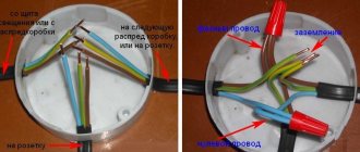
. In the distribution board it must be connected to the zero bus, which is designated by the Latin letter N. All blue wires must be connected to it. The bus is connected to the input via a meter or directly, without additional installation of the machine. In the distribution box, all wires (except for the wire from the switch) of blue color (neutral) are connected and do not participate in switching. To the sockets, the blue “zero” wires are connected to the contact, which is designated by the letter N, which is marked on the back of the sockets.
The designation of the phase wire is not so clear. It can be either brown, or black, or red, or other colors besides
blue, green and yellow. In an apartment switchboard, the phase wire coming from the load consumer is connected to the lower contact of the circuit breaker or to the RCD. In switches, the phase wire is switched; during switching off, the contact closes and voltage is supplied to consumers. In phase sockets, the black wire must be connected to the contact marked with the letter L.
How to find ground, neutral and phase in the absence of a designation
If there is no color marking of the wires, then you can use an indicator screwdriver to determine the phase; upon contact with it, the screwdriver indicator will light up, but not on the neutral and ground wires.
You can use a multimeter to find ground and neutral. We find the phase with a screwdriver, fix one contact of the multimeter on it and “probe” the wires with another contact; if the multimeter shows 220 volts, this is neutral; if the values are below 220, then it is grounding.
Letter and numeric wire markings
The first letter “A” denotes aluminum as the core material; in the absence of this letter, the core is copper.
The letters “AA” denote a multi-core cable with an aluminum core and an additional braid made of it.
"AC" is indicated in case of additional lead braiding.
The letter “B” is present if the cable is waterproof and has an additional double-layer steel braid.
“BN” cable braid does not support combustion.
"B" polyvinyl chloride shell.
"G" does not have a protective shell.
“g” (lowercase) bare, waterproof.
“K” is a control cable wrapped with wire under the top sheath.
"R" rubber casing.
"NR" non-flammable rubber casing.
Wire colors abroad
The color marking of wires in Ukraine, Russia, Belarus, Singapore, Kazakhstan, China, Hong Kong and the countries of the European Union is the same: Ground wire - Green-yellow
Neutral wire - blue
phases are marked with different colors
The neutral designation is black in South Africa, India, Pakistan, England, but this is the case with old wiring.
Currently the neutral is blue.
In Australia it can be blue and black.
In the USA and Canada it is designated white. You can also find gray labeling in the USA.
The ground wire is yellow, green, yellow-green in color everywhere, and in some countries it may also be without insulation.
Other wire colors are used for phases and may be different, except for the colors indicating other wires.
13 ways to save electricity
Core marking for electrical installation solutions
It is not for nothing that at the beginning of the article the idea was voiced that the color designation of conductors greatly simplifies the installation process. If you independently do electrical wiring in an apartment or private house, select wires according to the standards, when connecting electrical devices, installing automatic protection, distributing wires in junction boxes, you do not need to double-check where the phase, neutral, and ground are - the color of the insulation will tell you about this.
A few examples of electrical installations where marking is important:
- Depending on which electrical installations are connected and where the wires are sent next, the wires are connected in junction boxes
- For each core in the socket body there is a special contact. Typically the contacts, screw or clamp, are also marked
- The supply conductor is usually connected to the upper, fixed contacts, the ground - to the ground bus
- The simplest scheme: the neutral conductor is sent directly to the lamps, and the phase conductor is sent to the switch, from where it is also redirected to the lamps
There are cables with a large number of cores, the painting of which is not practical. An example is SIP, which uses a different method for identifying conductors. One of them is marked with a small groove along its entire length. The relief core usually performs the function of a neutral conductor, the rest play the role of linear ones.
To distinguish the cores, they are marked with tape, heat shrink, and letter designations, which are applied with multi-colored markers. And in the process of electrical installation work, a ringing is required - additional identification.
Grounding conductors (grounding conductors)
The most common color designation for grounding insulation is a combination of yellow and green. The yellow-green coloring of the insulation has the form of contrasting longitudinal stripes. An example of a ground electrode is shown in the image below.
Yellow-green coloring of the ground electrode
However, occasionally you can find either completely yellow or light green color of grounding insulation. In this case, the letters PE may be marked on the insulation. In some brands of wires, their yellow and green color along the entire length near the ends with the terminals is combined with a blue braid. This means that the neutral and grounding in this conductor are combined.
In order to clearly distinguish between grounding and grounding during installation and also after it, different colors are used to insulate the conductors. Grounding is performed with light blue wires and conductors connected to a bus marked with the letter N. All other conductors with insulation of the same blue color must also be connected to this zero bus. They should not be connected to switch contacts. If sockets with a terminal marked with the letter N are used, and at the same time there is a zero bus, there must be a light blue wire between them, respectively, connected to both of them.
Checking the correct connection
Unfortunately, not all electricians strictly follow the standards and make mistakes in choosing a conductor when making connections. Therefore, when hanging a chandelier, installing a socket or other electrical installation device, it is better to additionally check whether the insulation of each core corresponds to its purpose.
Mandatory checking of the neutral or phase is dictated by safety standards and the instinct of self-preservation: if you accidentally mix up the contacts during installation, you can get an unpleasant injury - an electrical burn. For identification, installers use two methods: the first is checking with an indicator screwdriver, the second is using a tester or multimeter. The phase is usually determined with a screwdriver, and neutral and zero are determined with measuring instruments.
How to use the indicator?
Even such simple devices as indicator screwdrivers are different. Some of them are equipped with a small button, others are triggered automatically when a metal rod and a current-carrying conductor or contact are connected.
But all models without exception have a built-in LED that lights up under voltage.
The indicator screwdriver is preferred by amateurs who do not have special qualifications. Professional electricians value accuracy, so they always have a tester with them. A screwdriver is a convenient tool for identifying the phase conductor. To find out whether the wire is working, use the metal blade of a screwdriver to gently touch the exposed wire.
If the LED lights up, the wire is energized. The absence of a signal indicates that it is ground or zero.
When using the indicator, you must adhere to the safety rules. Even if the screwdriver handle is insulated, it is recommended to wear protective gloves (with a rubberized inner layer), as when working with electricians in general. The verification procedure is performed with one hand, therefore, the other is free. It is better to also use it - for example, to fix wires. But it is strictly forbidden to touch the exposed parts of conductors or metal objects located nearby (pipes, fittings) with your second hand.
Rules for using the tester
An electrician's kit always includes a tester or multimeter. He has to work with the connection of conductors in electrical installations indoors and when assembling an electrical panel. If the wiring was installed a long time ago, marking the wires by color can be neglected.
Even if the insulation colors seem to be consistent, it is not a fact that they are connected according to all the rules.
Using the tester, you can find out not only the likelihood of connecting conductors to the electrical network, but also some parameters: current, resistance, voltage. With a multimeter you can test diodes, check transistors, and determine inductance. Before taking measurements, you should study the instructions that accompany all measuring instruments.
The procedure is approximately as follows:
- we set a value that is obviously higher than the expected voltage, for example, 260 V;
- connect the probes to the required sockets;
- we touch two conductors with probes - presumably phase and neutral;
- repeat the procedure with another pair of conductors.
The combination of phase-zero cores should produce a result close to 220 V. It will always be higher than the phase-ground pair. There are both digital, modern instruments on sale, as well as outdated ones, with arrows and value scales. It is more convenient to use digital ones. Before installing electrical devices yourself, we recommend learning how to use either an indicator screwdriver or a multimeter - you should not rely only on the color of the wires.
Color of zero, neutral
The “zero” wire should be blue
. In the distribution board it must be connected to the zero bus, which is designated by the Latin letter N. All blue wires must be connected to it. The bus is connected to the input via a meter or directly, without additional installation of the machine. In the distribution box, all wires (except for the wire from the switch) of blue color (neutral) are connected and do not participate in switching. To the sockets, the blue “zero” wires are connected to the contact, which is designated by the letter N, which is marked on the back of the sockets.
The designation of the phase wire is not so clear. It can be either brown, or black, or red, or other colors besides
blue, green and yellow. In an apartment switchboard, the phase wire coming from the load consumer is connected to the lower contact of the circuit breaker or to the RCD. In switches, the phase wire is switched; during switching off, the contact closes and voltage is supplied to consumers. In phase sockets, the black wire must be connected to the contact marked with the letter L.
How to find ground, neutral and phase in the absence of a designation
If there is no color marking of the wires, then you can use an indicator screwdriver to determine the phase; upon contact with it, the screwdriver indicator will light up, but not on the neutral and ground wires.
You can use a multimeter to find ground and neutral. We find the phase with a screwdriver, fix one contact of the multimeter on it and “probe” the wires with another contact; if the multimeter shows 220 volts, this is neutral; if the values are below 220, then it is grounding.
Letter and numeric wire markings
The first letter “A” denotes aluminum as the core material; in the absence of this letter, the core is copper.
The letters “AA” denote a multi-core cable with an aluminum core and an additional braid made of it.
"AC" is indicated in case of additional lead braiding.
The letter “B” is present if the cable is waterproof and has an additional double-layer steel braid.
“BN” cable braid does not support combustion.
"B" polyvinyl chloride shell.
"G" does not have a protective shell.
“g” (lowercase) bare, waterproof.
“K” is a control cable wrapped with wire under the top sheath.
"R" rubber casing.
"NR" non-flammable rubber casing.
Wire colors abroad
The color marking of wires in Ukraine, Russia, Belarus, Singapore, Kazakhstan, China, Hong Kong and the countries of the European Union is the same: Ground wire - Green-yellow
Neutral wire - blue
phases are marked with different colors
The neutral designation is black in South Africa, India, Pakistan, England, but this is the case with old wiring.
Currently the neutral is blue.
In Australia it can be blue and black.
In the USA and Canada it is designated white. You can also find gray labeling in the USA.
The ground wire is yellow, green, yellow-green in color everywhere, and in some countries it may also be without insulation.
Other wire colors are used for phases and may be different, except for the colors indicating other wires.
13 ways to save electricity
How to determine ground, zero and phase on wires if there are no markings
It is more difficult to determine in practice than in theory. Not all manufacturers comply with the standards. Therefore, when laying a two-phase 220 V network with grounding, you have to use a VVG cable with blue, brown and red colors. Combinations may be different, but without complying with regulatory requirements.
For your information. In old wiring from “Soviet times” there is no color marking. Identical white (gray) shells do not allow the purpose and correspondence of the lines to be known by simple visual inspection.
To avoid problems, it is recommended to carry out installation work using the same type of cable products. When color coding is not available, it should be created at the joints using insulating tape or heat shrink tubing. The latter option is preferable, as it is designed to maintain integrity for a long time.
Below are methods for determining phase and neutral wires with the advantages and disadvantages of each option. In any case, first clarify the network parameters. In old houses, for example, a two-wire connection scheme with a single working and grounding conductor is often used.
TN-S grounding diagram. The figure shows a modern network with separate grounding and working zero connections. It is possible to connect three- and single-phase loads.
Determining the phase using an indicator screwdriver
Touching the tip of such a device to the phase wire closes the current circuit. This is accompanied by the warning lamp or LED lighting up. A built-in resistor limits the current to a safe level.
Design of an indicator screwdriver.
Advantages of the indicator:
- minimum cost;
- compactness;
- reliability;
- durability;
- autonomy;
- good protection from adverse external influences.
The disadvantage is the limited measurement accuracy. Under certain conditions, false positives cannot be ruled out.
Determination of ground, zero and phase using a test lamp
To reproduce this technology, you need to prepare a simple design. An incandescent lamp designed for the appropriate mains voltage is screwed into a standard socket. Connect wires of sufficient length to perform work operations in a specific location. Next, connect one of the wires to the known zero line. Others sequentially check other cable cores. Lighting of the lamp indicates the presence of a phase.
Using a measuring device
When checking a 220 V household network, you do not need to know how to determine the polarity. The power supply is organized using alternating current, so set the multimeter switch to the appropriate position. Touching the phase-zero (phase-ground) wires with the probes is accompanied by an indication of the corresponding voltage (≈220 V). The potential difference between the neutral conductor and ground is minimal.
When checking an old two-wire circuit, one of the probes touches the reinforcement in a concrete slab, a radiator of a heating system, or another grounded element of a building structure. When switching to constant voltage, the multimeter will show where the plus and minus are. In the absence of reliable information about the electrical parameters in the circuit, they begin with the maximum measurement range with a sequential transition to smaller values with insufficient accuracy.
Such a “device” is useful for testing DC circuits in the absence of specialized measuring instruments. Bubbles near the negative wire are the release of hydrogen during the electrolysis reaction. The area near the plus will take on a greenish tint after a few minutes.
Using LED
You can create a control device with your own hands by analogy with an indicator screwdriver. Instead of a light bulb, install AL 307 or another LED with similar characteristics. A 100-120 kOhm resistor with a power of 1-2 W is added in series to the circuit.
Search for PE, L and N
Let's say that during the process of repairing the electrical network, you discovered that all the wires were painted the same color. How to figure out what each of the conductors means?
If a single-phase network does not imply the presence of grounding (there are only two wires in the network), then an indicator screwdriver is needed. This will help determine which of the wires is “phase” and which is “zero”.
Before the procedure, do not forget to turn off the power supply at the entrance panel. Next, you will need to carefully strip both wires of the network and separate them away from each other, after which you will turn on the current supply again. Now all that remains is to distinguish the “phase” from the “zero” using an indicator: upon contact with the “phase” wire, the light on the screwdriver handle will light up (from which it follows that the second wire is the desired “zero”).
In the same situation, when the wiring also has a third ground wire, you need to use a multimeter. In short, it is applied as follows. To begin, set the device's AC current measurement range to above 220 Volts. Next, lean one of the two tentacles against the phase conductor, and use the second tentacle to find “zero”/“ground”. In this case, in case of contact with the neutral conductor, a voltage value within 220 Volts will appear on the multimeter display. In case of contact with the ground wire, the voltage will be slightly lower.
There is another way to determine the types of conductors. It will help you when you have neither an indicator screwdriver nor a multimeter at hand. Logic and insulation color will help here. Remember that the blue shell is absolutely always “zero”. Identifying the remaining two wires will be a little more difficult. The first option is this: you are left with a colored and black/white contact, among which the colored one is most likely the “phase”, and the last white or black wire is the “ground”. The second scenario is also possible: in front of you there remains a red and black/white wire, where the white insulation (according to the PUE) means “phase”, and the remaining red one means “ground”.
What else I would like to say is that in a DC circuit the color marking of plus and minus is represented by the black and red colors of the insulating layer. In a three-phase network, each “phase” will have its own color (A – yellow, B – green, and C – red). In this case, “zero” will be blue, and “ground” will be yellow-green. In a 380 Volt cable, wire A will be white, B will be black, and C will be red. The neutral working and protective wires will be the same as in the previous version.
Wire Classification Options
The typical cable name contains letters and numbers. By decoding these symbols you can find out the main characteristics of products in this category:
- conductor (shell) materials;
- number of cores;
- cross-sectional area;
- Extra options.
Example of decoding (AVBbv-ng):
- A – the core is made of aluminum (copper is not marked);
- B – insulating shells are made of PVC;
- BB – protection against mechanical damage, made of steel tape without a damping gasket;
- ng – components that prevent combustion have been added to the polymer shell.
Ground wire color
By modern standards, the ground conductor is yellow-green. It usually looks like yellow insulation with one or two longitudinal bright green stripes. But there are also transverse yellow-green stripes in color. This color can be grounding.
In some cases, the cable may only have yellow or bright green conductors. In this case, the “earth” has exactly this color. It is displayed in the same colors on diagrams - most often bright green, but it can also be yellow. Signed on circuit diagrams or on ground equipment in Latin (English) letters PE. The contacts to which the “ground” wire must be connected are also marked.
Sometimes professionals call the grounding wire “neutral protective”, but do not be confused. This is an earthen one, and it is protective because it reduces the risk of electric shock.
What color is the neutral wire?
Zero or neutral is blue or light blue, sometimes blue with a white stripe. Other colors are not used in electrical engineering to indicate zero. It will be like this in any cable: three-core, five-core or with a large number of conductors.
What color is the neutral wire? Blue or light blue. “Zero” is usually drawn in blue on diagrams and signed with the Latin letter N. Experts call it a working zero, since, unlike grounding, it participates in the formation of the power supply circuit. When reading a diagram, it is often defined as "minus", while the phase is considered "plus".
Single-phase two-wire network 220V
This type of network includes an outdated type of wiring, where aluminum wires in a single white braid, popularly known as “noodles,” are used as cores. One core of the electrical wire is a phase conductor, the second core is a neutral conductor. A single-phase two-wire network is used for ordinary household needs: simple sockets and switches.
We talked about how to properly arrange an in-house electrical network in this article.
The problem when installing single-color wiring is that it is difficult to determine the phase and neutral wires. The presence of additional measuring equipment will help to cope with the task; you can use a multimeter or a special screwdriver with an indicator, a probe, a tester, or a “continuity tester”.
The design of a single-phase two-wire network is permitted by GOST for premises with a small load on the electrical network and low safety requirements. In such cases, two single-core wires or one two-core wire with wires of different colors are used.
When using a solid wire, one core is brown, the other blue or cyan. According to generally accepted markings, the brown conductor is a phase, and the blue conductor is a neutral conductor; it is strictly not recommended to violate this order. In practice, there are phase wires in colors other than brown: black, gray, red, turquoise, white, pink, orange, but not blue.
The use of two independent single-core wires also requires marking. You can use a wire colored along the entire length, for example, blue for zero, red for phase. It is permissible to mark wires of the same color with electrical tape or heat-shrinkable tubing of different colors, placing the marking on both ends of each wire.
The use of a tube does not involve wrapping the ends, but putting it on the wire and exposing it to hot air in order to fix the heat shrink on the wire. For home use, you can use any colors of marking materials that are accessible and understandable to the wiring installer.
Color of wires plus (+) and minus (-) in DC networks
Is the red wire positive or negative? Such questions arise when working with DC electrical circuits.
Red
To remember which plus is red or black, they use the name of a well-known international organization - the Red Cross. This phrase suggests that red means plus.
Black
Black color indicates the negative conductor. These markings can be seen on typical household equipment:
- power supplies;
- audio, video equipment;
- other devices with electronic software control units.
Plus
The polarity of conductors must be observed when repairing standard electrical equipment of cars. In some situations, confusion with plus and minus is accompanied by a violation of the functional state.
Minus
The high power of connected consumers increases the responsibility for performing repair and adjustment work. In such situations, it is necessary to eliminate errors in determining polarity. Strong direct current is used to supply electricity:
- warehouse and municipal transport;
- lifting mechanisms;
- sensors and automation.
Description of poles
In the case of an electric current passing between two points, or poles, one of the poles will have more electrons than the other. The pole with more electrons is said to have a negative charge. The pole with fewer electrons has a positive charge. When two poles are connected by a wire, electrons move from the negative pole to the positive pole. This flow is called electric current.
Polarity can be of different types
For your information! In a DC circuit, one pole is always negative and the other positive with electrons flowing in only one direction. In an alternating current (AC) circuit, the two poles alternate between negative and positive poles with the electrons flowing in the opposite direction.
Letter designation of wires
Color markings can be supplemented by letters. Partially the symbols for the designation are standardized:
- L (from the word Line) - phase wire;
- N (from the word Neutral) - neutral wire;
- PE (from the combination Protective Earthing) - grounding;
- “+” - positive pole;
- “-” — negative pole;
- M is the midpoint in DC circuits with bipolar power supply.
To designate the protective grounding connection terminals, a special symbol is used, which is stamped on the terminal or on the device body in the form of a sticker. The grounding symbol is the same for most countries in the world, which reduces the likelihood of confusion.
In multiphase networks, the symbols are supplemented by the serial number of the phase:
- L1 - first phase;
- L2 - second phase;
- L3 - third phase.
There is marking according to old standards, when the phases are designated by the symbols A, B and C.
A deviation from the standards is the combined phase designation system:
- La - first phase;
- Lb - second phase;
- Lc - third phase.
In complex devices, additional symbols may be found that characterize the name or number of the circuit. It is important that the markings of the conductors match throughout the entire circuit where they are involved.
Letter designations are applied with indelible, clearly visible paint on the insulation near the ends of the cores, on sections of PVC insulation or heat-shrinkable tube. Connection terminals may have marks that indicate circuits and power polarities. Such signs are made by painting, stamping or etching, depending on the material used.
Coloring phase
In cases where the electrical installation is installed using rigid metal busbars, the tires are painted with indelible paint in the following colors:
- yellow – phase A (L1);
- green – phase B(L2);
- red – phase C (L3);
- blue – zero bus;
- longitudinal or inclined stripes of yellow and green color – grounding bus.
The color of the phases must be maintained throughout the entire device, but not necessarily over the entire surface of the bus. It is allowed to mark the phase designation only at the connection points. On a painted surface, you can duplicate the color with the “ZhZK” symbols for paint of the corresponding colors.
If tires are not accessible for inspection or work when there is voltage on them, then they may not be painted.
The color of phase wires connected to rigid busbars may not coincide with them in color, since there is a difference in the accepted designation systems for flexible conductors and rigid stationary distribution busbars.
Additional marking of wires
If the purchased cable has conductors of a color that does not comply with the standards, or the wiring has already been laid and is incorrectly marked, additional identification must be carried out.
Additional marking of wires.
During the electrical installation process, the ends of the wires are marked using heat-shrinkable tubing or colored insulating tape. Additionally, the letter designation of the cores can be applied to the wire or a tag attached to the wire:
- L – phase.
- N – neutral (working zero).
- PE – ground (protective grounding).
Color of zero, neutral
The “zero” wire should be blue
. In the distribution board it must be connected to the zero bus, which is designated by the Latin letter N. All blue wires must be connected to it. The bus is connected to the input via a meter or directly, without additional installation of the machine. In the distribution box, all wires (except for the wire from the switch) of blue color (neutral) are connected and do not participate in switching. To the sockets, the blue “zero” wires are connected to the contact, which is designated by the letter N, which is marked on the back of the sockets.
The designation of the phase wire is not so clear. It can be either brown, or black, or red, or other colors except
blue, green and yellow. In an apartment switchboard, the phase wire coming from the load consumer is connected to the lower contact of the circuit breaker or to the RCD. In switches, the phase wire is switched; during switching off, the contact closes and voltage is supplied to consumers. In phase sockets, the black wire must be connected to the contact marked with the letter L.
How to find ground, neutral and phase in the absence of a designation
If there is no color marking of the wires, then you can use an indicator screwdriver to determine the phase; upon contact with it, the screwdriver indicator will light up, but not on the neutral and ground wires.
You can use a multimeter to find ground and neutral. We find the phase with a screwdriver, fix one contact of the multimeter on it and “probe” the wires with another contact; if the multimeter shows 220 volts, this is neutral; if the values are below 220, then it is grounding.
Letter and numeric wire markings
The first letter “A” denotes aluminum as the core material; in the absence of this letter, the core is copper.
The letters “AA” denote a multi-core cable with an aluminum core and an additional braid made of it.
"AC" is indicated in case of additional lead braiding.
The letter “B” is present if the cable is waterproof and has an additional double-layer steel braid.
“BN” cable braid does not support combustion.
"B" polyvinyl chloride shell.
"G" does not have a protective shell.
“g” (lowercase) bare, waterproof.
“K” is a control cable wrapped with wire under the top sheath.
"R" rubber casing.
"NR" non-flammable rubber casing.
Security measures
When working with electric current, the following precautions must be taken:
- Use devices only for their intended purpose;
- Do not turn on equipment with damaged wires and plugs, do not use faulty sockets;
- Do not touch wires or outlets with wet hands or while standing on a wet floor. When working in a room with high humidity, you need to use rubber gloves and a mat;
- Do not bend wires and cables;
- Before starting work, it is worth disconnecting the entire network;
- If the equipment sparks or starts to catch fire when turned on, do not touch it. It is necessary to turn off the power through the panel;
- If you have any doubts or fears, it is better to contact a specialist or choose a safer option, for example, determining the polarity using a potato rather than connecting to a device.
Most often in batteries, the red wire indicates positive, the black wire indicates negative, and there are no problems when working with electricity. However, today many countries use their own color designations or abandon them altogether, leaving the wires uniformly white. In order not to create emergency situations, it is worth checking the polarity first.