A home electrical network is a complex system of electrical installations and devices connected by electrical conductors. Wires are connected in electrical panels, junction boxes and device housings.
Let's look at how to connect wires without soldering using special clamps and terminals so that the switching is as reliable as possible and meets safety requirements. For this purpose, we provide 4 detailed instructions with the best ways to connect electrical wires.
We will also supplement our material with useful installation tips from experienced electrical installation specialists.
When to connect cables
Cable connections will be required in case of poor-quality wiring performed earlier, or due to errors made during installation work. To restore power to the house, you need to connect the electrical wires. You can make a connection in ways that are divided into 2 groups:
- For the first group, no special equipment is required.
- The second group already requires certain skills and professional tools.
Work on connecting cables must be carried out in compliance with safety regulations.
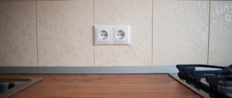
Connecting sockets
Usually a separate line is allocated to the sockets. The box contains three cables of two or three conductors. Each wire is painted a different color. As a rule, brown is the phase, blue is the neutral conductor, and the yellow-green wire is ground. One way or another, in the box all the wires are connected by color, forming groups.
Once the conductors are separated by color, they are folded, stretched, and adjusted to the same length. Don't cut too short - leave a 100mm margin so that you can re-connect if necessary. Having chosen the appropriate connection method, you need to connect the wires.
In old houses there is no grounding, which means there will be only two wires. Sometimes the wires in the cable are the same color. To determine where the phase is and where the zero is, you need to use an indicator screwdriver to determine the phase.
Types of cables for connection
The most common cable for home electrical wiring is a PVA connecting cable, consisting of two insulating layers.
Copper strands, stranded, twisted along the central axis. The wire is flexible, making it great for a variety of connections. The voltage of connected devices must be up to 380 Volts.
The cross section is selected depending on the load:
- for a current of 6 A, PVA with a cross section of 0.75 mm is used;
- for 10 Amperes - the cross-section is 1 mm;
- for currents of 16 A – 1.5 mm.
In addition to the PVS wire, for connection there are multi-core cables ShVVP, PUGNP, PRS, KG. They are used less frequently for home wiring than PVS.
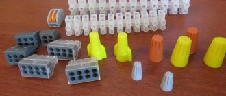
Self-clamping terminal blocks WAGO
In addition to terminal blocks with bolts, there are also terminal blocks with clamps. They are more expensive than usual, but they allow the connection to be made much faster, especially in connection with the new requirements of the PUE and the ban on twisting.
The most famous manufacturer of such terminal blocks is WAGO. Each terminal is a separate device with several holes for connecting wires, each of which is inserted into a separate wire. Depending on the version, it connects from 2 to 8 conductors. Some types are filled inside with conductive paste for better contact.
They are available for both detachable and permanent connections.
The stripped wire is simply inserted into the terminals for a permanent connection and spring tendrils fix the wire inside. Only hard (single-core) wire can be used.
In plug-in terminals, the wire is clamped using a folding lever and a spring clamp, making it easy to connect and disconnect wires.
Since the wires do not touch each other, the terminals allow you to connect wires of different sections, single-core to stranded, copper to aluminum.
This method of connecting conductors has proven to work best at low currents and is most widespread in lighting networks. These terminals are small in size and easily fit into adapter boxes.
What is the best way to reliably connect two cables together?
Methods of connecting cables that require equipment and skills in the field of electrical engineering:
- soldering;
- welding;
- crimping with sleeves.
Simple connection methods that do not require tools or knowledge:
- connection using terminal blocks;
- spring clamps;
- PPE caps;
- bolted connection.
The choice of connection method depends on the characteristics of the wires. It is necessary to take into account the type and material of the core, the number of wires, and operating conditions.
With soldering
Soldering is a common method of connecting cables. To work you need a soldering iron, rosin, solder and sandpaper. How to connect wires by soldering:
- stripping of insulation;
- cleaning from oxides using sandpaper;
- the conductors need to be tinned - rosin is placed on the wire, it is heated with a soldering iron until the wire is covered with rosin;
- the conductors are assembled together, bubbling rosin must be applied to them and heated until the solder spreads;
- The soldering area is cooled.
The complexity of the process lies in the availability of professional skills. Do not overheat the solder area or twist it when heating, otherwise the insulation may melt. It is important to ensure high-quality and reliable contact of the wires. Soldering is used in low-current electrical applications.
No soldering
Wires are connected without soldering using special connecting elements. It is also possible to connect the wires by twisting. Twisting is the simplest method that does not require equipment, but this method is also the most unreliable.
It is prohibited to use only a twisted connection according to the rules of the PUE.
Copper
Copper wire can be connected using terminal blocks, Wago clamps (necessarily using special paste), using a bolt, or soldering.
Aluminum
Aluminum wires can also be connected using any method, but with some special features. When connecting, the metal must be manually stripped of insulation.
Copper and aluminum wires cannot be connected directly. The connection point becomes very hot and over time the contact weakens. Therefore, it is better to use terminal blocks, wago, bolt connection or special branch clamps.
PPE caps: why electricians constantly argue about them
The basis for creating an electrical contact here is the same twist, but it is performed in a short section and is reinforced by compressed coils of the spring, immediately closed with a dielectric cap.
Similar connectors came to us from the west. They are now widely used in frame construction: installation is easy and quick, and is stipulated by the rules.
At first glance, the design is ideal for an electrician: the work is done quickly and does not require much effort. But there are many complaints about PPE caps (insulated compression). Let's dwell on them.
The caps are not universal. They are created for a specific wire size. A thinner section will not allow the spring to compress the twist normally, although it is made in a conical shape.
Careless installers do the twisting using pliers, and simply put the cap on it as insulation. Since it is poorly secured by springs, it often flies off, exposing the metal under tension, which is dangerous.
Initially, the twisting must be prepared, but the main pressing force is created by springs when manually screwing the housing clockwise.
Simple PPE caps have an insufficiently strong spring and a satisfactory dielectric body. Manufacturers improved their shortcomings by releasing the SIZ-K model, specified by the technical specifications of the TU 3449-036-97284872-2007 series.
They allow you to mount three cores in one housing due to the use of a special galvanized spring with a rectangular cross-section profile, which has increased adhesion to the metal of the conductors.
Reinforced wings on the body facilitate installation and reduce the manual effort that must be applied when screwing. The design of the lower part of the skirt has increased protection of the contact connection.
The insulation of PPE caps is designed for voltages up to 600 volts.
However, many electricians try to use this design only in lighting networks with small current loads, for example, when using LED lamps.
Independent tests under maximum loads do not show reliable performance of PPE. In addition, the market is flooded with beautiful fakes made using simplified technology.
Is it possible to connect cables by twisting?
According to the rules of the PUE, twisting is prohibited, as it does not provide reliable contact. It can only be used in conjunction with another connection method. It is also unacceptable to use twisting to join two different metals.
Stranded and single-core
When connecting multi-core wires, the following rules should be followed:
- strip the insulation by 4 cm;
- unwind the conductors by 2 cm;
- connect to the junction of untwisted conductors;
- twist the wires only with your fingers;
- You can tighten the twist using pliers;
- bare wires are insulated with special tape or heat shrink tubing.
Twisting solid wires is much easier. They need to be stripped of insulation, twisted by hand along the entire length, then clamped with pliers and insulated.
Twisting methods
You can do twisting in different ways. It can be made by branch, parallel or series connection. Also, to improve the reliability of contact, caps and clamps are additionally used.
Correct twisting of electrical wiring in a junction box
When twisting, you need to follow the following procedure:
- cut off power to a house or apartment;
- clear the wiring of 4 cm or more of insulation;
- unwind the wires by 2 cm;
- connect untwisted wires to the junction;
- twist the veins with your fingers;
- tighten the twist with pliers;
- insulate exposed wires.
Both single-core and multi-core cables can be connected.
Twisting of different sections
Do not twist wires with very different diameters. Such contact is not reliable and stable. You can twist wires of adjacent sections - for example, 4 sq. mm and 2.5 sq. mm. When twisting, you need to make sure that both wires wrap around each other. A thin wire should not be wound onto a thick one, otherwise the contact will be unreliable. Then you need to solder or weld the joint.
Twist caps
The caps help to reliably insulate the contact point.
The cap is made of fire-resistant material, inside it there is a metal part with threads. Making twists using caps is quite simple - you need to remove 2 cm of insulation and lightly twist the wires. A cap is put on them and turned several times until the metal wires are inside.
With terminal clamps
The contact clamp consists of a screw, a spring washer, a base, a current-carrying core and a stop that limits the spreading of the aluminum conductor. Making a connection using a contact clamp is simple - just strip the ends of the wires by 12 mm and insert them into the hole in the clamp. Contact clamps are used for both solid and stranded conductors.
How to brew twist
After twisting, the wires need to be soldered. To do this, the wires are tinned and rosin is applied to them before twisting. The heated soldering iron is lowered into the rosin; it needs to be passed along the stripped part of the wiring. After twisting, take tin on a soldering iron and heat the joint until tin begins to flow between the turns. This method takes a lot of time, but it is reliable and of high quality.
How to connect a switch with one key
If there is a switch in the room, then the connection in the box will be a little more complicated than with only sockets. There will also be three groups of conductors, but the connection is of a different type. Available:
— input cable – from another box or directly from the switchboard;
— wire for the chandelier;
- wire from the switch.
The circuit should work as follows. Power (that is, phase) is supplied to the switch key. From its output a wire is supplied to the lighting fixture. As soon as the switch contacts close, the chandelier will light up. The ground and neutral wires must be twisted together.
Methods for connecting wires or cables to each other
The junction of two conductors must meet the following requirements:
- reliability;
- mechanical strength.
These conditions can also be met when connecting conductors without soldering.
Crimping
This method requires special equipment. Crimping of wires with sleeves is carried out for both copper and aluminum wires of different diameters. Depending on the cross-section and material, the sleeve is selected.
Crimping algorithm:
- stripping of insulation;
- stripping wires to bare metal;
- the wires need to be twisted and inserted into the sleeve;
- the conductors are crimped using special pliers.
Selection of a sleeve causes major difficulties. An incorrectly selected diameter will not ensure reliable contact.
Bolted connection
Bolts, nuts and several washers are used for contact.
The connection point turns out to be reliable, but the structure itself takes up a lot of space and is inconvenient to install. The connection order is as follows:
- stripping of insulation;
- the stripped part is laid in the form of a loop with a diameter equal to the cross-section of the bolt;
- a washer is put on the bolt, then one of the conductors, another washer, a second conductor and a third washer;
- the structure is tightened with a nut.
Using a bolt, you can connect several wires. The nut is tightened not only by hand, but also by a wrench.
Terminal blocks
The terminal block is a contact plate in a polymer or carbolite housing. With their help, any user can connect wires. The connection occurs in several stages:
- stripping the insulation by 5-7 mm;
- removal of oxide film;
- installing conductors in sockets opposite each other;
- fixation with bolts.
Pros - you can connect cables of different diameters. Disadvantages - you can only connect 2 wires.
Types of terminal blocks for multi-core and single-core cables
There are 5 main types of terminal blocks:
- knife and pin;
- screw;
- clamping and self-clamping;
- cap-shaped;
- "walnut" type clamps.
The first type is rarely used; they are not designed for high currents and have an open design. Screw terminals provide reliable contact but are not suitable for connecting multi-core cables. Clamp terminal blocks are the most convenient devices to use; their installation does not require special equipment. Cap-type devices are also often used, but unlike clamping devices, caps can be used repeatedly. "Nut" is practically not used.
Terminals in junction box (copper or metal)
Terminals are the most common connection method in a junction box. They are cheap, easy to install, provide reliable contact fixation and can be used to connect copper and aluminum. Flaws:
- cheap devices are of low quality;
- Only 2 wires can be connected;
- Not suitable for stranded wires.
Self-clamping terminal blocks WAGO
There are 2 types of Vago terminal blocks used:
- With a flat spring mechanism - they are also called disposable, since reuse is impossible. Inside there is a plate with spring petals. When installing the conductor, the petal is pressed out and the wire is clamped.
- With lever mechanism. This is the best connector option. The stripped conductor is inserted into the terminal and the lever is clamped. Re-installation is possible.
With proper use, Vago terminal blocks last 25-30 years.
Using Tips
For connection, 2 types of tips and sleeves are used:
- in the first, the connection is made inside the product;
- in the second, two electrical wires are terminated with different tips.
The connection inside the sleeve or tip is strong and reliable. There are also special sleeves for connecting copper and aluminum wires.
Soldering of electrical wiring lugs
The tips are connected to the wiring using a press.
If it is not there, contact can be ensured by soldering. The electrical wire and the tip inside are tinned, the stripped cable is inserted inside.
The entire structure on the contact must be wrapped with fiberglass tape and heated with a burner until the tin melts.
Crimping
The connection is made using a special sleeve corresponding to the size of the wiring bundle. The sleeve must be made of a material similar to the cable material.
To crimp the product, press pliers are used, with the help of which the sleeves are crimped. At home, some people clamp the sleeve with pliers, but it has been found that such a connection will be weak and unreliable.
Instructions on how to connect the wires this way:
- Based on the length of the sleeve used for the work, remove the insulating material from the cables;
- twist the wires into a common bundle and place in the sleeve;
- crimp the connector using press pliers;
- insulate the resulting connection with heat shrink or electrical tape.
Connectors for wires and cables
Connectors are special devices that facilitate the connection of two or more conductors. There are screw and clamping mechanisms.
Screw terminals
Used to connect wires of different materials and different diameters. An exception is multi-core electrical wires, which are crimped with special lugs. Also, screw clamps can damage aluminum wires, so it is better not to use them for such material.
Screw terminals
Allows you to connect aluminum and copper conductors together. They are easy to connect.
Power clamp
In such clamps, the stripped conductor is placed in the hole to the end. There it is automatically fixed by a pressure plate. Clamps can be used to secure copper and aluminum wires.
Clips
To install the wire, the clip clamp is placed in a vertical position, the wires are inserted inside, and then the clamp must be moved to a horizontal position. Plus, you can make adjustments.
Spring clamps
PPE caps are used as spring clips. Thanks to them, you can quickly make contact between two wires of similar diameters. It is important to choose the correct clamp, otherwise the contact will be unreliable.
Spring terminals
Wago spring terminals ensure reliable contact quickly and efficiently. However, over time, the spring may weaken or overheat.
Connection clamps
There are two types - electrical and electrical. The only difference is the current load. The connection takes place inside the device.
Couplings
It is made in the form of a metal tube. Used for conductors with a cross section of 0.25-16 mm. The wire is fixed by force crimping. Not used for single-core wires.
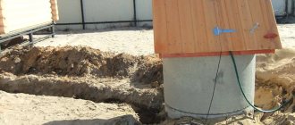
What is a junction box
From the electrical panel, the wires disperse throughout the rooms in the house or apartment. Each room, as a rule, has more than one connection point: there are several sockets and a switch. To standardize the methods of connecting wires and collect them in one place, distribution boxes are used (they are also sometimes called branch boxes or junction boxes). They contain cables from all connected devices, the connection of which occurs inside the hollow housing.
In order not to look for wiring during the next repair, it is laid according to certain rules that are prescribed in the PUE - Rules for the Construction of Electrical Installations.
Electrical wiring rules
One recommendation is to carry out all connections and branch wires in the junction box. Therefore, the wires are run along the top of the wall, at a distance of 15 cm from the ceiling level. Having reached the branch point, the cable is lowered vertically down. A distribution box is installed at the branch point. It is where all the wires are connected according to the required circuit.
According to the type of installation, junction boxes are either internal (for hidden installation) or external. Under the internal ones, a hole is made in the wall into which the box is built. With this installation, the cover is flush with the finishing material. Sometimes during the renovation process it is covered with finishing materials. However, such installation is not always possible: the thickness of the walls or finishing does not allow it. Then a box for external mounting is used, which is attached directly to the wall surface.
Some forms of junction boxes
The shape of the junction box can be round or rectangular. There are usually four conclusions, but there may be more. The terminals have threads or fittings to which it is convenient to attach a corrugated hose. After all, it is more convenient to lay wires in a corrugated hose or plastic pipe. In this case, replacing the damaged cable will be very simple. First, disconnect it in the distribution box, then from the consumer (socket or switch), pull it and pull it out. Tighten a new one in its place. If you lay it the old fashioned way - in a groove, which is then covered with plaster - you will have to drill into the wall to replace the cable. So this is the recommendation of the PUE, which is definitely worth listening to.
What do distribution boxes generally provide:
- Increased maintainability of the power supply system. Since all connections are accessible, it is easy to determine the area of damage. If the conductors are laid in cable channels (corrugated hoses or pipes), replacing the damaged section will be easy.
- Most electrical problems arise in the connections, and with this installation option they can be inspected periodically.
- Installing distribution boxes increases the level of fire safety: all potentially dangerous places are located in certain places.
- Requires less money and labor than laying cables to each outlet.
Safety Tips and Rules
Only craftsmen with a qualification group are allowed to weld.
Persons who have skills in working with a soldering iron are also allowed to solder. Cables may only be connected in the manner permitted for them. Do not work with damaged wiring. All exposed parts must be insulated.
You can connect the cables in different ways. The choice of connection method is determined by the material, cross-section diameter and other parameters. For electrical equipment to operate correctly, the conductors need to be connected securely. In case of unreliable contact, there is a risk of fire.
Welding fastening
To create the most reliable connection of the conductors after twisting, they are additionally secured by welding. The technology for making such a contact is very similar to soldering, only here a welding machine is used instead of a soldering iron.
In terms of quality and reliability, the welding method fully meets all regulatory requirements for creating electrical contact.
When creating a connection by welding, the conductors are twisted and their tip is welded. The resulting metal ball provides a very reliable connection of the wires. At the same time, reliability is due not only to the creation of high electrical characteristics, but also mechanical ones.
The main disadvantage of this type of wire connection is the presence of a welding machine and devices for such work. In addition, it is necessary to strictly adhere to the rules of working at height and fire safety.
Sequence of welding wires:
- We strip the conductors from insulation by 60-70 mm.
- We clean the cores mechanically (sandpaper).
- We twist the wires, and its length must be at least 50 mm.
- We fix the welding grounding contact on top of the twist.
- Lightly touch the bottom of the twist with the electrode. Wire welding occurs very quickly.
- After the contact ball has cooled, we insulate it.
As a result of such actions, an almost solid conductor is obtained, and the contact node will have the lowest transition resistance.
Twisting method
The simplest and most well-known method of connecting electrical wires is twisting them (twisting). Experienced electricians often call it the old-fashioned method.
Previously, this type of connection was used everywhere, but with the increase in load in the electrical network of a modern apartment, twisting became prohibited. However, this connection method must be studied first, since it is the main step in soldering and welding wires.
The main advantage of twisting is the absence of any material costs, since you only need pliers and a knife to remove the insulation. And of course, the advantage of twisting is the ease of its execution. Anyone who has held pliers in their hands can do this job without any problems.
Over time, the twist weakens, which is its main disadvantage. This process is connected with the fact that in any veins there is residual elastic deformation. Therefore, at the point of twisting, the contact resistance increases, which leads to weakening of the contact and heating of the conductor. It’s good if this defect is discovered in time and the joint can be redone, but a fire may occur.
But if for some reason you do not have the opportunity to use more reliable methods, then you definitely need to familiarize yourself with how to properly connect the wires to each other using the twisting method. To do this, you first need to strip the cores of 70-80 mm of insulation. Then, holding both conductors where the insulation ends, use pliers to grab the ends of the wires and rotate them clockwise. The main condition for reliable twisting is the simultaneous rotation of the conductors, and not alternately winding them on each other.
If the diameter of the wires is small, then twisting can be done entirely by hand. With your left hand you need to hold the conductors along the cut of the insulation, and with your right hand you need to rotate the conductors by the bend (10-15 mm) clockwise. For tighter contact at the end of the rotation, you can use pliers.
The next step is to insulate the junction of the wires. Insulating tape is used for this. To ensure reliability and protect the contact from moisture, you need to wind the tape in several layers, with 2-3 cm of overlap between the wire insulation. A very good option for insulation is the use of thermal tubes; the main thing is not to forget to put it on one of the cores.
Professional electricians advise not to stop at the stage of twisting the wires, but to strengthen the joint by soldering or welding.
Soldering tips
Another way to use the tip is to solder it. To do this you need:
- stripped copper cable;
- tip designed for soldering. It is distinguished by a hole near the flat part and a thinner wall;
- bath of molten tin;
- a jar of phosphoric acid;
- a jar of soda solution.
Carefully! Wear protective glasses and gloves!
In order to solder the tip, the cable is cleared of insulation along the length of the tubular part and inserted into the tip. Then the tip is successively immersed in orthophosphoric acid, in molten tin for a time sufficient for the acid to boil away and the solder to flow into the tip. This is checked by periodically briefly removing it from the solder. After impregnating the tip and cable with solder, the tip is dipped in a soda solution. This is done to neutralize acid residues. The cooled tip is washed with clean water and is ready for further work. Such a tip can be connected to aluminum busbars and lugs without the use of adapter washers.
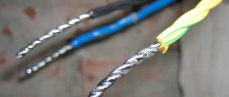
Preparing a Stranded Conductor
When stripping the end of a stranded copper conductor, it turns out that the thin wire cable begins to change shape. Before this, the twist was held in place by a layer of insulation, but now the hold is gone, residual elasticity causes the wires to straighten, and the rod fluffs up into individual elements. Each unconnected wire:
- Reduces the overall nominal cross-section of the joint, the permissible current density through the contact drops, the temperature rises;
- If left outside the insulation, it may cause electrical injury and short circuit.
Pre-treatment of the stripped ends of the stranded wire is required to prevent fraying and obtain a homogeneous, monolithic section.
Service
Until recently, one of the more accessible, popular methods of preparation was tinning. For this:
- The insulation is stripped to the required length, the wires are carefully twisted tightly together;
- Using a heated soldering iron, melted rosin is transferred to the surface of the core. The metal warms up, the rosin impregnates the wire rope;
- The tip of the soldering iron tip picks up solder and transfers it to the tinning site. The solder spreads over the surface of the hot wires, filling all the gaps, forming a molecular bond with the metal;
- After cooling, the remaining rosin is removed with gasoline or alcohol, and the surface is treated with sandpaper to remove possible “strings” of solder in the form of thin long needles.
Has the meaning:
- Rosin is a flux that is used during soldering to remove oxides from the metal surface, improves heat transfer and heat distribution at the soldering site. For tinning the conductors, it is prohibited to use fluxes containing acid or other active components for removing oxide, which will lead to destruction of the conductor;
- Lead-tin solder is used. The retail chain offers a huge number of solder pastes, consisting of a mixture of solder and flux. They are very comfortable. It is allowed to use only those that have a mark on the trade label indicating that the flux is not active.
But, if the soldering iron is still hot, the easiest way is to tin the same hard conductor and connect them by soldering. The result is a strong, reliable joint with minimal contact resistance.
The method requires a soldering iron, consumables, the presence of electricity at the installation site, work skills, careful careful execution, and takes a lot of time.
Crimping
This method of preparing the stripped end of a flexible core requires the presence of press jaws and consumables - sleeves, the internal diameter of which corresponds to the diameter of the core. The process takes incomparably less time and labor than tinning:
- The stripped end of the strand is twisted tightly and placed in a sleeve;
- Press pliers compress the outer surface of the sleeve, tightly clamping the wire with the body. The resulting dents hold the cores more securely.
The finished pressed end is used in any type of joint. If you need to connect it to a single-core one, it makes sense to immediately take a sleeve, the diameter of which will allow you to place two conductors inside it. Simultaneous crimping will give a good joint. In this case, preliminary tinning of the stranded wire is not required.