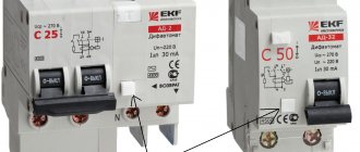
The markings applied to the body of each device include a set of numbers, diagrams, letters, and special symbols. The markings are made with indelible paint and are on the visible part. This is required for accessibility during operation after installation on a distribution panel with connected wires.
Circuit breaker model
Important! To check the markings, you do not need to remove the devices from the DIN rail and disconnect them.
Each manufacturer uses its own designations. Most specialists in their work are faced with the type of arrangement of signs on household modular machines, which can be understood by deciphering the symbols and signs.
Regardless of the company where the device was manufactured, the same data is applied to the case:
- manufacturer's name printed at the very top;
- indication of the model (series) with letters and numbers of the device series in accordance with the manufacturer’s data;
- rated current, shutdown characteristic, designated by the letter of the Latin alphabet “B”, “C”, “D”, “K”, “Z”;
- data on the rated voltage, showing the maximum value passing through the machine without switching off at an ambient temperature of 30 ° C, at which a kind of shield is formed for increased load;
- indicators of the rated breaking capacity that each electrical machine has;
- parameters of the current limiting class of the circuit breaker;
- panel information about the switching diagram.
Order of symbols on the outer panel of the device
Please note! Manufacturers specify parameters without fail. There are some indicators in the general list, taking into account the marking data of which is especially important for uninterrupted operation.
Marking of electrical machines - designations on the body
All circuit breakers have certain technical characteristics. To familiarize yourself with them when choosing a machine, markings are applied to the body, which includes a set of diagrams, letters, numbers and other symbols. Friends will agree that the appearance of the machine cannot say anything about itself and all its characteristics can be recognized only by the markings applied.
The marking is applied on the front (front) side of the machine body with durable, indelible paint, so you can familiarize yourself with the parameters even when the machine is in operation, that is, installed in a distribution panel on a DIN rail and wires are connected to it (no need to disconnect the wires and pull them out). it from the shield to read the markings).
In the picture below you can see several examples of how electrical machines from different manufacturers are marked. Each of them is clearly marked with different letters and numbers. In this article we will not disassemble industrial protection devices, but will only touch on ordinary household modular circuit breakers. But in any case, the article will be of interest not only to beginners, but also to professionals, “bisons” who deal with this every day, and will also be interested in remembering the basics of their profession.
Which is better: rigid or flexible wire when installing a distribution panel?
The main difference between a rigid wire used for an electrical panel and a flexible one is the ability of a flexible wire to bend in the desired direction up to 12 times (decreases over time), as well as the ease with which it bends.
As a rule, to connect automation in the distribution board, professional electricians use flexible wire PuGV. Because it is more convenient to work with it. For work carried out independently by residents or unskilled workers, rigid wire is often used.
In both the first and second cases, the required build quality can be achieved. However, a wiring diagram assembled using a flexible wire looks more aesthetically pleasing.
Marking of machines
Each machine has its own marking, which consists of alphanumeric and conventional graphic images used to identify and convey to the consumer its main technical characteristics. They are necessary for the correct selection and further operation of the machine.
- manufacturer's name or trademark;
- designation of type, catalog number or series number;
- rated voltage value;
- rated current values without the symbol “A” with the preceding designation of the type of protective characteristic (A, B, C, D, K, Z) and current limiting class;
- rated frequency value;
- the value of the rated maximum breaking capacity in amperes;
- connection diagram if the correct connection method is not obvious;
- the value of the control ambient temperature, if it differs from 30 °C;
The marking of difavtomats is similar to the AB marking, but contains additional information:
- rated residual current;
- settings of the disconnecting differential current (for DV with several values of the disconnecting differential current);
- rated maximum differential making and breaking capacity;
- a button with the symbol “T” for operational monitoring of the performance of the DV by differential current;
- symbol "
» - for DV type AC;
- symbol for DV type A.
- single-pole circuit breaker with a protective characteristic of type “C” for a rated current of 16 A: Switch VA47-29-1S16-UHL3
- four-pole circuit breaker with a protective characteristic of type “C” with an unprotected pole for a rated current of 100 A: Switch VA47-100-4NC100-UHL3.
Explanation of circuit breaker symbols
Along with the marking of the switches, the necessary information about the characteristics and type of the AV contains its symbol, which is required to place an order for the purchase of the AV.
The symbol of the circuit breaker is as follows: VA47-Х1-Х2Х3Х4ХХ5-УХЛ3
Explanations for the symbol AB are given in the table.
| Symbol | Decoding |
| VA47 | Switch series designation |
| X1 | Switch type |
| X2 | Number of poles |
| X3 | The letter “N” in the presence of a pole without a release |
| X4 | Type of protective characteristic |
| XX5 | Rated operating current |
| UHL3 | Designation of climatic version and placement category (according to GOST 15150) |
For products of the UHL3 design, the operating temperature range is from minus 60 to +40 °C.
Each machine mounted in an electrical panel is marked in accordance with its functional purpose. For example, room number, designation of feeder, equipment, etc. to protect the electrical circuits of which this machine is installed.
We begin internal installation
Now let's figure out how to properly assemble the electrical panel. First of all, a din rail is installed in the shield using self-tapping screws. It consists of a metal plate to which all switching devices will subsequently be attached. To create the required length, it can be easily cut with a hacksaw.
In addition to the DIN rails, terminal blocks (or distribution busbars) are attached to the panel body. Their role is to connect the neutral conductors. If the apartment or house is an old model and the entire system is made of only a phase (3 phases) and a working zero (done with a blue wire), one terminal block is enough. If the system is made according to the rules and there is an additional yellow-green conductor (protective zero or grounding), then it is necessary to install another bus. At the moment, there are tires on sale, the design of which allows them to be mounted on a DIN rail, just like automatic machines.
After installing the DIN rails, we proceed to attaching the circuit breakers. Modern design allows you to do this very quickly; just pull out the latch device on the top side of the machine with a flat screwdriver, place the machine on the DIN rail and remove the screwdriver. Removal is carried out in the same way.
Assembly instructions
The following is a step-by-step description of how to assemble a single-phase electrical panel:
- We strictly observe precautions!
- We attach the required number of DIN rails to the panel.
- After fixing them, according to the chosen scheme, we install the required number of automatic devices, RCDs, and zero busbars. It should be remembered that according to the rules, the introductory machine should be placed at the top left.
- We install an electric meter (if space allows). This is specific equipment that requires special knowledge, so it is better to simply connect the wires to it and call a controller from Energosbyt, who will make the correct connection, and at the same time draw up a report and seal the meter.
- We connect the input machine. It will be better if the phases are brought to it from below. In the future, this will simplify the task when installing jumpers between machines.
- We connect all the machines and RCDs with special jumpers. In the question: “How to assemble an electrical panel?” This point is worth paying attention to.
Assembling the distribution panel
The connection can be made in three ways:
- Using stranded copper wires with sleeve lugs of the NShVI type.
- Make U-shaped jumpers with your own hands from pieces of copper wire.
- Using special insulated tires called combs. This bus is easy to install and does not take up much space, plus it reduces the number of connecting wires several times.
- After all the necessary steps for assembling the electrical panel have been completed, proceed to cutting and connecting the conductors.
- With cutting, everything is simple - we clean off the excess insulation with a knife.
- After removal, it is advisable to solder the bare ends or equip them with special crimps, which are also better to solder.
- We connect the wires to the machines - the terminals must be tightened well with a screwdriver, weak contact will subsequently lead to heating and destruction of live parts.
- The grounding conductor always goes past the machines directly from the grounding bus.
- The neutral conductor is connected to the neutral bus. If a regular circuit breaker (except the input one) is used as protection, the zero goes directly; if the protection is performed by an RCD, the zero goes through it to the connected line.
What else do you need to know?
Installing an electrical panel and assembling it is not only about knowing how to assemble the circuits correctly. You also need to know some nuances so that you don’t later regret the time and effort spent.
- Under no circumstances should you skimp on the shield you buy! The cheapness of the shield clearly indicates the low-quality materials from which it is made. Cheap plastics yellow and become brittle over time. Fire resistance may also be low.
- It is better to buy a shield with a supply of modules. It should be possible to maneuver in a larger direction.
- Installed machines must be signed! After a while, you may not remember which machine serves what. Often, the electrical panel comes with adhesive paper that serves just these purposes.
- Six months after assembly, it is necessary to broach the contacts.
- Periodically test the RCD by pressing the corresponding button.
- It is better to buy equipment from well-known brands. In such boards, everything is prepared for convenient, high-quality and safe cabling and installation of protective devices. For example, assembling a legrand or abb electrical panel will take less time due to the availability of the necessary components.
- For convenience, we place the distribution busbars on different sides. Grounding – at the bottom, zero – at the top.
- If there are children in the house, the shield must be purchased with a lock or equipped with one.
It must be recalled that assembly and installation of the electrical panel of Legrand, ABB or equipment from another company must be carried out strictly on a disconnected power line, after checking that there is no voltage.
To connect the assembled panel to the existing system, it is necessary to involve employees of relevant organizations. For apartment buildings, these are representatives of the homeowners association or housing office.
As a result, after completing the entire assembly and connection process, you need to close or screw the cover and check your work by applying voltage to the live parts of your shield.
Installation diagram with three input phases
Single-phase connection diagram
Electrical wiring diagram in the apartment
Tips for choosing a circuit breaker
The machine is selected based on certain characteristics, many of which can be recognized by the markings on the front panel.
In addition to the analyzed characteristics, you should know other nuances of choice. For example, before purchasing a machine, be sure to calculate its power and select the required number of poles.
More information about the calculation and selection of a circuit breaker is written in this article.
The brand is important, as is the condition of the wiring.
No selectivity of protection
If the circuit breakers are not selected correctly, then in the event of a short circuit in one of the outgoing lines, the input protection device of the electrical panel may turn off. To select types of switches, use selectivity tables provided by equipment manufacturers. For more information on selecting circuit breakers that provide the required levels of selectivity, see the article Selectivity of protection in power supply circuits.
Viktor Chernov about violations of electrical installation rules - electrical panels
vote
Article rating
Shield markings, the simplest solution
A good electrician knows that correct marking is not for beauty, but, first of all, for convenience. Moreover, for the convenience of the electrician himself. When the shield includes three to five cable lines, you can mark it in any way you like: marker, tape, electrical tape. what if there are several dozen lines? Should I wrap each wire with electrical tape or tape and sign it with a marker? For larger volumes, you can buy a marking printer. But what if the volumes are small, or are you renovating your own apartment? Print the stickers on a printer and cover them with tape? Mark the wires with electrical tape, and sign the machines with a marker on the plastron? You can, of course, do this, but it’s long, tedious, and looks terrible. There is a better solution: buy an album with electrical markings, and do it right, quickly and accurately!
There are people who love their work. They do it with pleasure, often, come up with something new and bring their ideas to life. One of these people is Alexey Medvedev. This is an electrician, a panel assembler. It was he who came up with the idea to combine in one album all the necessary markings for one object.
Alexey Medvedev, compiler: “The albums were compiled based on my personal experience and the experience of the installers who helped me with this. The marking was created for registration of rough and finishing electrical installations in the apartment.”
It is clear that at different objects the number of groups, the size of the shield and the content will vary. Therefore, there are two types of albums on sale: “for a small apartment” and “for a large apartment.”
- Volume 1 - for small properties (small one-room or two-room apartment)
- Volume 2 - for a large two-, three-, four-room apartment.
Next up is Volume 3 for a country house, cottage.
Electrical marking album, what is it?
As mentioned above, the album includes electrical markings for rough and finishing electrical installations. The album is in A4 format (landscape sheet). Consists of individual sheets of vinyl stickers secured together with a spring. The marking is pre-cut, self-adhesive. That is, you simply peel the sticker off the base and stick it where needed. There is no need to cut, write, or glue anything. At the same time, you know exactly what you have marked and what you have not. One album is for one object.
Electrical marking album, what's inside?
The album contains stickers and tables for work. In fact, such an album can serve as an object’s passport. It starts with the group assignment table. There are 19 groups in the first volume, 38 in the second.
Following the table are stickers for marking with group numbers.
Next, rough labels for wire and cable labels, with product names and load types. It is clear that in the second volume there are more such stickers than in the first.
For marking inside the shield, colored stickers are provided on the plastron.
There are also special stickers for the shield.
In addition, the album contains blank stickers for self-labeling, a sheet with a table of configurations of clean electrical installation equipment, a lined blank sheet (for example, for listing switchboard equipment and components, for compiling a list of works, etc..) and a blank sheet “For notes.”
Albums vary in the number of stickers. There are much fewer of them in the first volume, and it is designed for no more than 19 groups. The second volume already contains stickers for 38 groups. It has more stickers for wire signatures, more stickers for plastron. In general, it is 50 percent thicker than the first volume.
What else is important to know
The photo below shows the board in which the wires were marked during installation:
When assembling an electrical panel, electrical wiring groups should be marked as follows: the input wire is marked as L, and the output wire is marked Gr (indicates that these are groups). After the letter the group number and line number are indicated.
Also, during marking, it is important to take into account all color differences so that an emergency situation does not arise. If, after opening the cabinet, no markings were found, then you need to use a probe to determine where each wire is located. We talked about how to use an indicator screwdriver to determine phase and zero in the corresponding article. Since this will take a lot of time, it is better to leave marks when checking so that another electrician who will carry out repairs or maintenance can understand where which wire is.
If there are no conductors of the required color, then you can use any color, as long as the ends of the cores are correctly marked during installation. This can be done using colored electrical tape or special heat-shrinkable tubes.
Heat shrink markings look like this:
This is the technology used to mark wires and cables when installing an electrical panel. As you can see, marking the lines is very important, and the process itself does not take much time. Please note that with the help of these instructions you can mark conductors not only in power electrical panels, but also in automation panels (for example, to mark signal cables and control).
It will be useful to read:
You want to change the parameters of the input switch (if it is knocked out)
One of the reasons is that your input circuit breaker is constantly knocked out at the same time as the internal circuit breaker in the distribution panel. And this didn’t happen before. Why is this happening? There are switches on the home panel with a similar maximum current value. For example, you had a 25 A ceramic fuse in your entrance (an old house). After repairs, it was replaced with a modern 20 A circuit breaker. And the distribution switches in the apartment have the same rating. It would seem easier to replace the machine at the entrance, and everything will fall into place. However, this is fraught with a fine from the energy supply company.
We will have to redo the home panel and install group circuit breakers with a lower value.
Technical requirements
Installation inside the switchboard is usually carried out using single-core wires of the appropriate cross-section and color. The incoming cable must be connected directly to the main machine, and the outgoing cable to the corresponding group one. Zero working conductors - to the terminal bus.
The working neutral wire (N) from the input cable passes through the main circuit breaker, and the neutral wires from consumers should not pass through group circuit breakers, only directly to the common working neutral bus. The protective neutral (PE) wire should not pass through any machine, only directly to the grounding bus.
It is advisable to mark the cables in any way; if the wires in the cable are multi-core, then they must have appropriate tips at the ends for connection to the terminal blocks.
Since there can be quite a lot of distribution wires in the panels, it is also advisable to mark them or even sign them with a permanent marker in accordance with the panel diagram, this will facilitate maintenance and repair in the future.
For better contact, it is necessary to install lugs on the ends of the wires; their type is selected depending on the installed machines and terminal blocks. The picture below shows the main types of tips.
Types of lugs for electrical wiring
The lugs are sold for wires of any cross-section; their use increases the reliability of contact; installing them on the wire is not difficult. Strip the end of the wire to a length of approximately 10-12 mm, place a tip of appropriate diameter on the wire and crimp it with a special device (press pliers).
Press jaws PC 16
Using this hand tool, lugs are crimped on wires with a cross-section from 1.5 to 16 mm 2; at home this is quite enough.
Install terminal blocks as a common bus for the working zero.
After the preparatory work, they proceed directly to installation, and the following procedure for assembling the electrical panel can be recommended:
- Install the introductory circuit breaker and the main RCD.
- Install group machines.
- Install automatic circuit breakers and RCDs for individual consumers.
- Mark all machines and RCDs.
- Connect the group machines with a jumper or comb between each other and the input machine.
- Connect the machines of each group with their consumers.
- Connect individual consumers to their own switches.
- Connect all working neutral wires to a common terminal bus.
- Connect all protective neutral wires to the ground bus.
- Check for correct installation.
- Connect the main circuit breaker to the input cable.
Operating principle of the machine
The photo of the machines in the panel makes it clear what the device looks like: a white, opaque plastic box of an elongated shape with a colored control lever and holes for connecting to the line. The body is marked with appropriate markings about class, power and other parameters.
Each machine has an identical design consisting of the following elements:
- Housing made of non-flammable plastic;
- Control system, which is a lever or on and off buttons;
- Terminals at the top and bottom for connecting the device to the circuit;
- DIN rail mounting;
- Switching device;
- Arc suppression chamber, which cools and extinguishes the electric arc that appears during network failures;
- Position indicator;
- A release, depending on the type, that initiates shutdown of the current supply by exceeding the permissible temperature (thermal), load current (magnetic) or provides the ability to set a time delay in the event of a circuit short circuit.
Unlike a plug with a fusible insert, the bag has undeniable advantages:
- Operation accuracy;
- Indicator indicating enabled or disabled status;
- Possibility of quick shutdown by lowering the lever;
- Multiple uses.
Our services
Do-it-yourself assembly and installation of an electrical panel: choose
The panel itself is a plastic or metal box in which components are placed (or modules, each of which performs a specific function. Let’s name a few “iron” distribution rules, following which you can begin assembling the electrical panel yourself. On the top and bottom of the panel (sometimes in the back) there are usually perforated holes that can either be squeezed out with a finger or trimmed with a knife. So, let’s summarize all of the above and give some tips on choosing an electrical panel: First, you must first of all choose a conscientious seller from whom you can buy absolutely everything : electrical panel, all modular equipment, all components, and everything that is useful during installation.
A unique design can be found from the Greek company Fotka. Yes, and it will be easier for a beginner to work with this wire. How to find out how much you need? If you are guided by the tabular data, then for a device with a power of 2 kW, a 5 mm wire, as well as a 10 A circuit breaker, is sufficient, but to create some reserve, as a rule, components of the next level are installed; in some cases (if the consumer’s power exceeds. What advice, in conclusion, the team of authors would like to give to readers.
RCDs protect against precisely such troubles. There should be more to the doorway or slope. In the first case, all elements are arranged one after another in the order shown on the single-line diagram: automatic input device, RCD, automatic circuit breakers, consumer circuit breakers. The safety and reliability of the equipment largely depends on the quality of the purchased materials. For unused places in the shield, you will need the required number of plugs so that all the insides of the shield are securely closed after its final assembly.
Installation of the mounting rail (DIN rail) inside the switchboard housing. This applies to washing machines and dishwashers, air conditioners, ovens and electric stoves, water heaters and other devices with a power exceeding 2 kilowatts. Mono-core wires cannot be placed in a nshvi type lug. How to determine the required size?
Installation of a panel for an apartment: diagram, assembly, installation
The RCD must be in the electrical panel. Nshvi and nshvi lugs (2) Clamping two different wires into the terminal of a modular device is prohibited. The input is made with a VVGng cable 3*6 mm2. Fastening all components, including the meter, to the bus. This area is equal to the space occupied by a single-pole circuit breaker.
On high-quality panels, such an input is usually provided; low-quality ones are better not to be considered at all. In the absence of comb bars, you can “distribute” the phase and working zero among the devices using self-made combs from pieces of PV3 wire of the corresponding color, connected in pairs with nshvi lugs (2). Linear layout diagram of RCDs and circuit breakers Group diagram. Minimum requirements when designing a switchboard In addition to the importance of the preliminary calculations that we talked about above, when creating a switchboard diagram, it is necessary to take into account some nuances. And there is no way to avoid this issue, since no modern home can live without electricity. And such powerful devices as an electric hob or instantaneous water heaters may already “require” a 6 mm2 cable and a circuit breaker with a rating of 32 Amperes.
How to properly assemble an electrical panel: diagrams, what to buy
For power and socket lines, you should choose an RCD with differential operating current. It is better to do this when all electricity consumers are turned off. Therefore, you will need to make at least two or three points. The circuit is the most common, since a two-pole input circuit breaker allows you to distribute zero and phase to all automatic circuit breakers and RCDs using two-pole combs. All consumer groups should be signed on the external panel of the electrical panel.
The small device has many important functions. In a suspended structure, it is simply the cables that are inserted into the hole one by one. Installation will be made into a brick wall; the technology used is similar to installation in other structures. Remove the knife a few millimeters before the marking. Monitor the correct installation and nominal values of the modules. As for the package switch, it cannot be replaced or repaired independently; this can only be done by specialists.
Place the tip in the crimper and crimp. How to properly form consumer groups. The first type connects the phase conductors and is painted gray, the second makes contact with the neutral conductors. For example, an intermediate distribution board usually does not require the installation of a meter. Well-known companies always provide the opportunity to complete the electrical panel with various accessories: cross-modules, zero busbars, locks, combs, doors of various colors.
It is better to choose this device as selective, which means that it should not react instantly, but will “wait” for some time for the RCDs located closer along the wiring to the problem area to operate. Break out the required hole and insert the cable. It is possible to replace the switch with an automatic switch, but its design negatively perceives shutdown during load. Built-in electrical panel Based on the housing material, electrical panels are divided into: Panels with a metal casing. When distributing, you should ensure that different wires intersect with each other as little as possible.
How to assemble an electrical panel with your own hands: selection, installation
Selective RCD, for a more understandable perception of the electrical panel diagram, it can be viewed in a more attractive form, where all the conductors and all devices are painted. The warps of the bundles are fastened with plastic ties. For crimping there is a special tool called a crimper, or as electricians call it a crimper. There is no way to do this without calculations or without science.
This is not so noticeable on 2-3 modules, but in a whole series of 12 modules there is a problem with the docking combs. These are RCDs and differential circuit breakers and circuit breakers whose lines are not protected by RCDs. Under no circumstances should this be done! Assembling the shield Having developed the diagram and decided on the components, you can begin direct assembly. The input zero bus and PE bus are usually included in a set of good panels, and they are not mounted on a DIN rail, but are located on the top and bottom of the case. The Nshvi tip (2) is available for wire cross-sections from 0.5 to 16 mm2, but we should be interested in the most common sizes in household electrical panels: 4, 6 mm2 and very rarely 10 mm2.
After the test run, it is necessary to once again conduct a careful inspection of the switchboard and the entire system for a burning smell, sparking or tripping of circuit breakers. The presence of cable organizers that will greatly help organize the internal space. That is, they brought the cable into the shield, stretched it through it and measured its height from the border again. One module is considered as a unit of measurement here. Again, in favor of famous manufacturers, we would like to say that their kits already have such covers.
We present the installation and switching process in the form of a table. If a powerful consumer of electricity is connected to one of the phases (for example, a welding machine or some kind of power tool, this can lead to the so-called phase imbalance, when the voltage on one of them drops to critically low values. Depending on the specific purpose of the panel, there may be additional elements are installed or vice versa, some are not required.The first is the load switch or water circuit breaker, followed in order, as shown in the single-line diagram, are all the RCDs and differential circuit breakers, and then, in order, all the circuit breakers.
Element marking system in DDECAD diagrams
DDECAD uses the following alphanumeric marking system for circuit elements: ABC , where
- A - numbers correspond to the group number;
- B - letters unique for each type of element, comply with GOST 2.710-81;
- C - numbers that correspond to the ordinal element of a device of this type in the group.
Let's look at this system using several examples.
Example No. 1
Group No. 2. Automatic installed. The machine will be marked 2QF1.
Example No. 2
Group No. 3. An automatic device is installed, followed by an RCD. The machine will be marked 3QF1, the RCD - 3QSD1.
Example No. 3
Group No. 4. Two circuit breakers were installed in a row (this type of circuit is used for backup protection against short circuit currents). The first machine will be marked 4QF1, the second machine - 4QF2.
Let's consider more complex cases.
Example No. 4
It is necessary to implement the following scheme: a general circuit breaker (group 5), followed by three contactors. In the calculation table we mark the groups through a dot: 5.1, 5.2, 5.3. Then in the circuit the machine will be marked 5QF1, and the contactors 5KM1, 5KM2, 5KM3.
Printing devices and instruments
To apply inscriptions to marking elements, special devices have been developed, which can be divided into several types:
Portable automatic and semi-automatic devices
Canon MK 1500 printer
One of the modern devices for automatic printing on stickers, PVC casings and heat-shrinkable tubes is the Canon MK 1500 printer.
It is possible to select several types of fonts and set cropping modes at different intervals. Printing speed is 2.5 cm per minute, on a 20 mm tube you can print 35 markers per minute with 5 full-size characters.
Hotmarker M-3E
The Hotmarker M-3E printer prints characters on cables, casings and flat tapes using the hot stamping method. The printer's heated dies press the ink into the cable sheath. The matrix has the shape of a wheel, on which there are 10 + space symbols, a total of 7 matrices, this allows you to form thousands of combinations. This printer is capable of marking products with a diameter of 13 mm.
Stationary printers
Brady LabelMark
Used in large-scale production where it is necessary to mark large volumes of products with different types of markers. Brady's software allows LabelMark to quickly change from one program to another. Within 6.5 seconds, it prints characters and sticks a tag on the cable.
The program is placed on a regular PC and transferred from it to the printer. To operate the program and operate the printer, no special highly qualified training is required. The device has a high print resolution, up to 300dpi, which allows you to print small fonts and clear images of logos. Symbols are applied to wires with diameters of 1.5-15.2 mm, maximum marker dimensions 50.8 X 50.8 mm.
| Specifications | ||
| Printing technology | thermal transfer | |
| Print Resolution | 300 dpi (300 dpi) | |
| Production cycle duration, seconds | 4,5 — 6,5 | |
| Minimum wire diameter, mm | 1,52 | |
| Maximum wire diameter, mm | 15,24 | |
| Maximum print width, mm | 50,8 | |
| Maximum print length, mm | 41,3 | |
| Maximum label width, mm | 50,8 | |
| Maximum label length, mm | 76,2 | |
| Minimum label width, mm | 6,35 | |
| Minimum label length, mm | 19,05 | |
| Ribbon outer diameter | 68.58 mm | |
| Fonts, Barcodes, Graphics | Printing fonts, barcodes and graphics are consistent with LabelMark™'s label creation capabilities . For more information on this issue, check out LabelMark™ software. | |
| Interfaces and connectors | USB, Serial RS-232C, Ethernet, PCMCIA, CompactFlash | |
| Memory | Built-in 4Mb Memory expansion 32Mb RAM using PCMCIA or CompactFlash® | |
| Dimensions, mm | 571.5 x 368.3 x 450.9 | |
| Weight, kg | 38,5 | |
| Operating temperature | from 10° to 41° C | |
| Storage and transportation temperature | -18° to 60° C | |
| Humidity | from 20% to 80% without condensation | |
| Nutrition | 90-264 V AC, at 47-63 kHz | |
Office laser printers
Used when printing on sheets of self-adhesive stickers or regular sheets of A4 paper. Tags are placed on the cables and wrapped with transparent tape. This is a simple and cheap way for small volumes of marking.
Tip #1. Do not buy expensive marking equipment if you are not professionally involved in electrical installation work. Use low cost labeling methods.