Today, manufacturers supply many different electrical products to the construction market. Let's look at what the junction box is used for. Let's get acquainted with the criteria for selecting products depending on the purpose and operating conditions. Read to the end and you will find out what must be taken into account for the proper installation of electrical communications inside or outside the building, in dry, dusty or damp rooms.
Variety of electrical junction boxes Source sellpax.com
Purpose of distribution boxes
Electrical wiring must be divided into groups depending on the energy consumer. For this purpose, similar structures are installed that perform important tasks:
- ensuring fire safety;
- aesthetics.
Under the body of the box there are conductors, which are thus protected from various damages. This allows you to increase the service life of electrical wiring.
Junction box with conductors
The main task of the distribution box
With this design, you can reduce the budget for organizing electrical wiring. After all, in the absence of a distribution box, a cable would have to be connected to each electrical appliance, which would create too many channels that would have to be hidden in the ceiling. In addition, all this does not look aesthetically pleasing.
At the same time, the correct distribution of conductors inside the box increases the level of fire safety in any type of room. This is due to the insulation of connections and flammable materials that are located in the wall. In addition, this design is convenient for repair work.
However, the main function of the distribution box is to distribute electricity between consumers that are installed in a specific room. In addition, the design of the product allows for expansion by adding additional branches (when it is necessary to install a new switch or socket).
You can add a branch to the distribution box for a new energy consumer
Design
The design is quite simple and consists of a container with a lid, as well as inlet openings - seals (if the container is of an external installation type). The photo shows in detail the components of the electrical distribution box, hidden and external:
As you can see, the products are different from each other, but still perform the same function.
Please note that the distribution box for hidden wiring may have claws with springs installed on the sides. Their purpose is additional fixation if installation is carried out in a plasterboard wall.
Why does the box have different names?
This piece of electrical equipment goes by several names, including: distribution box, branch box, junction box. Only their operating principle is the same: the box is a center where electricity is supplied from the power source, and then it is distributed through separate channels that go to switches, sockets and other devices. Therefore, such a design is usually called “distribution”. Otherwise, the box is also called a “branch”, this is due to the fact that only one cable goes into it, but several channels come out.
Note! The boxes are also called soldered boxes, which is due to the way the wires are connected inside. So, the wires must be soldered after twisting. We will talk more about this and other connection methods below.
Among some electricians, you can find another name for this box – “disconnection box”. This word is formed from two definitions: distribution and connection. After all, first you have to distribute the wires and then connect them to consumers.
Distribution boxes installed in the wall
Accordingly, if a store consultant calls the box differently, you shouldn’t be surprised, because it’s the same product. Rather, you should pay attention to the dimensions of the box, because you will have to make a recess in the ceiling for it. As a rule, standard products are produced in the form of a rectangle measuring 10x10x5 centimeters.
Prices for distribution boxes
Junction box
Protection class
The main characteristics of branch boxes also include the protection class (GOST 14254-96), which is indicated as IPXX, where XX is a digital designation. Moreover, the first number indicates resistance to dust, the second - to moisture. Below are tables that list the protection class codes.
Table for the first digit:
| Code | Description |
| no protection provided | |
| 1 | penetration of particles larger than 50 mm is not allowed |
| 2 | penetration of particles larger than 12 mm is not allowed |
| 3 | penetration of particles larger than 2.5 mm is not allowed |
| 4 | penetration of particles larger than 1 mm is not allowed |
| 5 | The device is protected from dust deposits |
| 6 | The device is protected from dust penetration |
Table for the second digit:
| Code | Description |
| no protection provided | |
| 1 | The device is protected from vertically falling drops, such as condensation |
| 2 | The device is protected from drops falling at an angle of up to 15° |
| 3 | The device is protected from drops whose angle of incidence does not exceed 60° |
| 4 | Provides comprehensive protection against drops and splashes |
| 5 | comprehensive protection against water jets |
| 6 | comprehensive protection against high-pressure water jets |
| 7 | The device is protected from water penetration during short-term immersion to a depth of one meter |
| 8 | The device is completely sealed (can be used underwater) |
Using this table, you can easily determine the operating conditions of the device, for example, if the protection class IP65 is indicated on the branch box, this indicates that the device is completely protected from dust and does not allow moisture to enter when a jet of water hits it.
Will it be possible to do without junction boxes during the installation of electrical wiring?
Of course, it is possible to install wiring in an apartment without junction boxes, but this is impractical - then you have to pull many cables from the main panel to the power consumers, which is why deep grooves are made in the wall, which will have to be puttied. In addition, this involves spending money on the purchase of cables, so the only rational solution is to purchase distribution boxes for premises.
Corrugated pipes for electrical wiring
However, some users mistakenly believe that the connection point, which is located inside the box, is less secure than the whole cable. In fact, with proper installation, there are no problems with the junction box and wiring connections.
In addition, if you imagine that the box is missing and a malfunction has occurred, you will have to remove the wallpaper and chisel the wall to find the damage. If there is a design, it will be enough to remove the cover and inspect the condition of the electrical wiring.
What's new in the VK SamElectric.ru group?
Subscribe and read the article further:
Important! I'm not entirely sure that the middle contact in the switch is 2 and 5. The diagram is drawn somehow implicitly...
In conclusion, I would like to note one more difference between pass-through switches and conventional ones.
The number of wires to the pass-through switch is not two, but three. And four wires should be connected to the crossover. This must be taken into account in advance when laying the wiring.
In conclusion, I will note one more difference between pass-through switches and conventional ones. The number of wires to the pass-through switch is not two, but three. And four wires should be connected to the crossover. This must be taken into account in advance when laying the wiring.
Types of distribution boxes
You can find a large number of varieties of these designs on sale. Therefore, to choose one of them, you need to familiarize yourself with these types in more detail.
Designs have different appearances
Table No. 1. Types of junction boxes according to installation method
| View | Description |
| Open | Such boxes are not mounted into the wall, but fixed on the surface, which looks less aesthetically pleasing. Therefore, they are most often used in industrial-type premises to provide quick access to electrical wiring. In addition, similar products can be found in private houses made of timber. |
| Hidden | This type of junction box is most often used for residential premises. The structure is mounted in a pre-prepared hole. Some types require decorative covers, so they are not covered with a layer of plaster. This also allows you to have constant access to connections. |
Table No. 2. Materials for making the case
| View, illustration | Description |
| In this case, several materials of artificial origin are used to make boxes: polypropylene, polyamide, fluoroplastic. Such designs are popular among users regardless of the type of structure. They have many advantages: · high-quality insulation; · resistance to mechanical damage; · resistance to chemicals and fire. |
| Such boxes are used extremely rarely in domestic conditions, only if it is necessary to distribute wiring in a storage room or garage. Most often they are used in public places, in production, and are installed in an open way. These boxes are made from various aluminum alloys. |
Table No. 3. Types of distribution box configurations
| Type | Description |
| Without internal filling | Such designs are a type of body and cover. As many electricians note, this option is suitable for installing electrical wiring yourself. Products without filling have the following advantages: · you can make the connection of wires in the box in a convenient way; · If installed correctly, the contacts will not become loose. |
| With additional terminals | This type simplifies the installation process because it involves quick connection of wires with clamps. The disadvantage is that such boxes are not installed in rooms with high humidity levels, because the terminals begin to oxidize over time. |
"Empty" junction box
Products also differ in the number of inputs. At a minimum, the design is designed for two inputs (to connect two cables), and a maximum of sixteen inputs. It is necessary to choose one type or another based on the electrical wiring diagram of the room.
The designs also differ from each other in the degree of protection, so this criterion should also be paid attention to when choosing a box. This is important when installation needs to be done in a room with high humidity or high air temperature.
What do junction boxes protect against:
- The standard product assumes the presence of sealing rubber. As a rule, this is enough for most areas of the apartment.
- From dust particles. This is relevant at production facilities.
- From the water. Such boxes are installed in the bathroom, toilet, room with a swimming pool.
- From mechanical shocks. This is true if the box is installed outdoors.
- From exposure to high temperatures. Such products are purchased if there is a log house or if the walls are decorated with flammable materials.
In shape, the boxes are square, round and rectangular - the latter are used when there are many cables. Round designs are used when there is a small number of cables. In addition, they are often chosen for concrete floors.
General description of products
Engineering communications are a network of a central channel, branches, and end points. For the system to function properly, it is necessary to form reliable nodal connections of individual elements. In the case of electrical wiring, the event is carried out using electrical junction boxes.
In fact, the device is represented by a box with a lid. Install it at each node branch. The main goal here is to isolate contact connections from possible environmental influences and unauthorized mechanical influence. It also protects the premises from fires during a short circuit and protects people from electric shock. Additionally, two problems are solved: access to contact nodes for various purposes, and a decorative component.
Where is the distribution box installed?
Most often, they prefer to install the junction box under the ceiling at a distance of approximately 25 centimeters from it. This is associated with the safety of using electrical wiring, because the possibility of the protective cover falling off cannot be ruled out, which will cause electric shock to a person.
Junction boxes are fixed at height
Note! Another reason for accurately calculating the location of the box is the cable consumption for network wiring. Therefore, the closer you can bring the conductor to the consumer, the shorter the branch from the box to this point will be.
Prices for popular models of wall chasers
Wall chaser
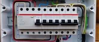
Installation of a distribution box in a residential area
In this case, you will need to prepare the following devices and materials:
- A jigsaw with a special disk for creating grooves where the wires will be placed.
- A hammer drill is needed when you plan to “sink” the box into the wall, so you will need to prepare a hole.
- Hammer for additional cutting of openings after using a core drill.
- Wire cutters - for cutting wires to the required length.
- Wiring stripping tool.
- Additional devices for connecting cores.
- Tester.
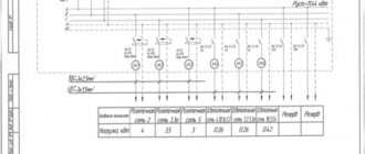
Electricity supply diagram
Approximate power supply diagram for an apartment
In the diagram you can see where the distributors are installed. So, if there are few sockets and switches in the room, then here you can determine where to install additional channels.
Installation of a distribution box: step-by-step instructions
Step 1. First you need to display on the wall the lines where the grooves will go, according to the diagram.
Grilling is performed along these lines
Step 2. Next, in the designated places you need to make recesses for installing the boxes.
It is necessary to secure the box to the wall with self-tapping screws or plaster
Step 3 . Wiring is inserted into the box and connected to each other.
After connecting, check that the wiring is working properly
Step 4. Now all that remains is to close the box with the lid.
Putty is not applied to the decorative cover
Note! They try to secure the cover in such a way that when removing it the surface of the wall is not damaged.
Video - Installation of distribution box
Misconceptions and errors in detecting electrical wiring in the wall
The above describes how to find a wire in the wall using instruments and improvised means. But there are supposedly “folk methods” for detecting hidden wiring, which will not help at all and will take extra time:
- Using a compass . There is a theory that using a compass you can find the cable. But this is a myth, since it is impossible to create the necessary magnetic induction at home for the compass to respond.
Sometimes they try to look for wiring with a regular magnetic compass. Source survival-mastery.com
- Using a magnet as a hidden wiring finder . There is a hypothesis about a magnet tied to a rope and its action: if you move along the wall, it will deflect in the place where the electrical wires pass. And following the vibrations, mark the expected locations of the wires. But this method will not bring any benefit.
- Finding hidden wiring using a smartphone . A very dubious method, based on an installed special application that supposedly can find the cable. Smartphones have a built-in magnetic sensor and, using the application, the phone turns into a metal detector. But such a device will react to anything that contains metal parts in the wall.
Methods for connecting wires in a junction box
There are several basic ways to connect the wiring in a junction box. In order to choose one of them, you need to consider the options in more detail.
Stranding and insulation
This is an old, but proven method of connecting wiring over the years. The bottom line is that the ends of the conductors are first stripped of the insulation layer and then twisted together with pliers. After which this place is wrapped with electrical tape.
Twisting conductor strands
This method has advantages:
- ease of installation;
- no need for additional expenses.
However, there are some disadvantages:
- poor-quality connection of cores;
- inability to connect copper and aluminum wires.
It is worth noting that conductors are often connected in this way during temporary installation of electrical wiring. According to safety regulations, the connection method is not suitable for rooms with high humidity levels.
Soldering or welding
It is in these ways that you can make a durable connection of wiring cores. First, their ends are carefully stripped of the insulating layer, then twisted, but without effort. Next, you will need to solder the wires using solder and a soldering iron so that they turn out monolithic. Then you need to wait until they cool naturally, and only then wrap them with electrical tape.
Soldering wire cores
In cases of soldering thick wires, you will need to use a soldering iron with a dense copper tip.
Note! Some would-be craftsmen do not want to wait for the veins to cool naturally, so they cool them under running water. However, this should not be done - microcracks will appear on the surface.
The advantage of soldering is the reliability of the connections, but this method also has some disadvantages:
- the need to purchase a soldering iron;
- this is a labor-intensive process that not every beginner can handle;
- the connection is permanent;
- Over time, the level of resistance in the soldering increases, which leads to voltage leakage.
Often, instead of soldering, the cores are connected by welding. The process has a similar principle, only here a welding machine is already used, so the master must have the appropriate skills.
Video - Soldering twists
Crimping with sleeves
This is also one of the most reliable methods of fixing conductor cores. Here they are placed in a special sleeve and clamped with a crimping tool on both sides. After which this sleeve is wrapped with electrical tape or a cambric is attached to it.
Crimping of conductor cores
It is worth noting that the cores are placed in the sleeve either from different sides or from one. In the case of the first option, they will be connected in the central part of the tube. When choosing the second option, it is necessary to take into account that the diameter of the cores should not exceed the volume of the sleeve.
The advantages of such a connection should be noted:
- reliability;
- affordable cost of sleeves.
Disadvantages of the method:
- The sleeve is used only once. This means that in case of repair, it is torn down and a new one is fixed.
- You will need to use a special tool for high-quality crimping on all sides.
- Wires made of aluminum and copper are crimped only with special tubes, which are difficult to find in stores.
- Electrical installation will take time.
Terminal connection
If the wiring is made of different materials, it is recommended to use special clamps with springs or screws. Connecting the conductors using this method is not difficult; all you need is a screwdriver. The main thing is not to overtighten the bolts.
Connecting wires with clamps
Wiring diagrams
It is necessary to become more familiar with the features of connecting the wiring from the junction box to consumers.
Prices for various types of voltage indicators
Voltage indicator
Connecting sockets
Often sockets are connected in groups on one line. So, 3 cables with several conductors are placed inside the box. Brown indicates the phase conductor, blue indicates neutral, and green or yellow indicates ground. Of course, some manufacturers use other colors.
Connecting sockets
The wires are laid out on a flat surface, and then cut to a certain length, but with a margin (so that it can be separated again). Next, it remains to fix them according to the diagram.
Connecting a switch with one button
This is where installation becomes more complicated. After all, there are three groups of electrical wiring with different connections. One conductor is responsible for supplying voltage from another box or panel, the second comes from the lighting fixture, and the third from the switch.
The phase conductor is fed to a switch, which is connected to the lamp. Here you should make sure that the voltage supply occurs precisely when the switch is closed. The neutral and grounding conductors from the lamp are connected to the shield.
The principle of connecting a switch with one button
Connecting a switch with two buttons
A three-core cable is connected to this type of switch (without a grounding conductor, because it is connected directly to the panel). The first conductor goes to the common contact of the switch, the second to the first button, and the third to the second button.
Note! The phase conductor is connected to the common contact, the zero is fixed directly from the board and lamps. The phase wires from the lighting fixtures are fixed with the cores on the buttons.
Connecting a switch with two buttons
A simple indicator of hidden wiring on one transistor
Even a person far from radio engineering can assemble an indicator on one transistor on his own. The circuit is simple, the main element is the field-effect transistor KP103 or KP 303.
Hidden wiring detector circuit using one transistor
The source of the transistor is connected to the “+” of the power supply, the drain to the “minus”, through a 1.6 kOhm microphone capsule from an old phone and a switch. The gate of the transistor is used as an antenna; a copper wire of 8-10 cm with a cross-section of 1-2.5 mm2 is soldered to it.
Appearance of field effect transistor KP 103
The accuracy of detecting a hidden wire with such a device is 3-5 cm; the work is based on the change in resistance between the drain and the source when exposed to an electric field. You can connect a multimeter in the 200 kOhm measurement mode to the circuit between the drain and source to monitor the maximum resistance value as the antenna approaches the wire.
A similar circuit can be assembled using 561 series microcircuits, its operating principle is the same.
Hidden wiring detection detector on K561 chip