Not only qualified electricians should have knowledge of the basics of installing electrical equipment. It is better for home owners to familiarize themselves with the basic provisions for assembling and operating an electric box that controls the supply of energy to all consumers in the apartment.
Knowing how and in what sequence the electrical panel is switched off, even the owner of an apartment or house who is far from electrical work will be able to quickly respond to a problem in the system - call an electrician or solve the problem on his own.
Purpose of the electrical panel
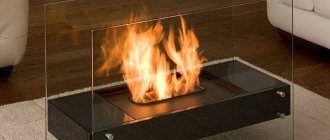
Externally, products in which protective and accounting equipment are installed look different. This can be a compact plastic box with tinted glass installed in the hallway, or a large metal panel mounted into the wall on the landing.
We are talking about an electrical panel, which is necessarily present in residential buildings, office buildings, in production - wherever power lines are laid.
Electrical panels, depending on the installation location and purpose, can be distribution, group, accounting and distribution. For example, a box with a counter is called an accounting and distribution box, and a box in the hallway in which only machines are located is called a group box
Possible installation locations are specified in the regulatory documentation, but largely depend on the purpose of the shield. For example, for private houses, one of the electrical panels, with an electric meter and an input device, is usually installed on the street, on a pole or facade.
Shield functions:
- receiving electricity from the central main line - a power line connected to the house;
- energy distribution among consumer groups or individual lines;
- protection of the electrical network from high loads and short circuits;
- accounting for quality and stabilization of electricity;
- protection of power grid users from electric shock.
Simply put, the uninterrupted transmission of electricity to the house, the safety of all residents, and the safety of property will depend on the correct assembly of the electrical panel.
Installation and connection
Installation steps
All devices that are mounted in the electrical panel have standardized dimensions, which greatly facilitates installation. For the main fastening, you can use a DIN rail, which is made in the form of a metal profile. Seats are measured in modules. This unit corresponds to 1 unit of space occupied by a single-pole automatic switch.
When calculating the places that will be used in the panel, it should be taken into account that 2 modules are one two-pole circuit breaker, and 3 modules are one three-pole circuit breaker. When installing a single-phase RCD, 2 modules will be required, and for a three-phase RCD, four. One module fits one terminal block, and an electric meter may require from 6 to 8 modules (it all depends on the design).
In general, it is recommended to assemble the shield on a flat, flat surface, for example, on a table. Doing the same thing on a wall will be much more expensive. Be that as it may, strengthening the shield must be done before filling from the inside.
First, install an input device for automatic protection. After this, the cable connection diagram can be made in two versions:
- In a linear diagram, all RCDs are located after the input circuit breaker, and after the circuit breakers. In this case, it will be difficult to find the fault that has appeared on the line.
- According to the group scheme, we first install a common RCD for the group, and only then the machines. In this case, in the event of an emergency, one group will be disabled, and the rest will operate in normal mode.
Installation of devices is carried out according to general rules:
- The wires inside and at the input of the panel must be of the same cross-section.
- Each device must be placed so that there is an entrance at the top and an exit at the bottom.
- Multicore wires can be clamped using NShVI lugs.
- To connect two wires in one terminal, use lugs that are designed for two wires.
Before you start disconnecting the cable, connect all the wires that are components of the entire apartment/house circuit to the electrical panel. Now you can start collecting. All models must be located on a special surface and secured with clamps. If necessary, you can move each device, and thereby be able to free up space for another device. After this, everything is connected with wires, which also need to be prepared in advance.
Connecting wires and cables in the panel
First you need to remove the insulation from the wires. After this, you can start connecting the wires to each other. If you use stranded conductors, then it will be convenient to make everything with lugs with the cross-section you need, the crimping of which is carried out using press pliers.
The technology for disconnecting the cable is much simpler thanks to the use of special tires. They have flat pins that look like pins that connect to the pins. These combs are not produced for all types of devices and will not fit other models due to the different pitch of the pins. Because of this, it is recommended to buy a single set from one manufacturer in order to simplify your work in the future.
Excess wires are cut off, leaving only what is needed for connection. When making connections, you must strictly observe the color markings, which correspond to different cores and conductors. When making connections with violations, you can create all the conditions for a short circuit, fire or breakdown of conductors.
Exclusion what is it
Disconnection of the distribution box (Wiring) is carried out by an experienced specialist. According to the PEU, electrical connections of wires should be made only in junction boxes.
By contacting Efas LLC, you can be confident in the reliability, quality, and durability of this work. We provide a 5-year warranty on the wiring of junction boxes . Very often you can find a poor-quality connection of wires, which can cause a fire, or simply a loss of voltage in an apartment, house or workplace. Remember that now there are a lot of “specialists”, but not many will perform high-quality wiring of the box .
Box wiring
Disconnection of distribution boxes is carried out in several ways: Soldering, crimping, welding, using terminals, clamps. All these methods can be used when disconnecting junction boxes . The most reliable method is crimping and welding, but this takes more time and requires special equipment and experience.
Network switching
Switching is the process of switching in electrical circuits when different sections of the circuit are closed or opened. Each element of the electrical circuit (socket, switch, lamp) is combined into a distribution box . Then in this junction box it is necessary to connect the wires in the required ratio so that the switch is a switch and not a socket and vice versa. To do this, you need to be guided by the PUE.
General information
Among what will be required for improvement is the selection of elements, installation and disconnection of cables in the electrical panel. I would like to immediately note that to perform such work you need special knowledge and practical skills in electrical engineering. But if you have instructions, ready-made diagrams, an electrical panel and you know all the safety requirements, you can assemble the panel and figure out how to connect the cable cores yourself.
Electrical panel - what is it for?
The distribution panel that is familiar to us, which is installed at the entrance to a private house or apartment, is needed in order to ensure safety when using electrical equipment and devices. In houses of a new type, such panels are already provided, but even in old buildings they are gradually replacing traffic jams and meters. Using a shield, you can intelligently distribute energy between all groups of consumers and create excellent protection against short circuits and overloads.
For placement you will need a plastic or metal box. First, they install an electric meter and a general switch to completely cut off power to the apartment. This shutdown can be done manually, or it will work itself in an emergency (network overload). If an input machine is installed in front of the meter, then it must be sealed (and the meter too).
Of the group of devices, circuit breakers have the most number of devices. They not only protect the wiring, but also the household appliances themselves. For each machine, a group of consumers is defined, and for each powerful device they install their own machine. Thus, you can turn off the devices individually, or the switch will work automatically in the event of an emergency.
In addition to automatic machines, residual current devices are also installed in the panel. They are needed to compare outgoing and incoming currents and are triggered if the balance is upset. This usually happens due to uncontrolled current leaks, and shutdown occurs due to exposure to current that is safe for humans.
And lastly, there are special busbars in the distribution panel, which are made in the form of copper strips. You can connect machines and other devices to them. The neutral wires go to a special block with terminals - the zero bus. To connect grounding, use a grounding bus.
Consumers and their distribution
All electricity supplied to the facility must be evenly and correctly distributed among all consumers.
When distributing and disconnecting cable cores, you must be guided by special rules and regulations:
- Consumers that are considered powerful (from 2,000 W and more) are grouped into different groups. Each group should be connected to a machine that can withstand the load.
- Connect the washing machine and dishwasher, as well as air conditioning and other devices that are not very powerful, to 16 A machines. Please note that the cable cross-section should not be less than 2.5 mm 2.
- Powerful devices (over 380 V) must be connected to 20 Am or 32 Am circuit breakers. In this case, the cable cross-section must be at least 4 mm 2. The cable should not have branches, and it should be laid in whole pieces.
- Connect separate lines to the sockets for each room and, if using a three-core cable, the cross-section of which will be at least 2.5 mm 2. Separate branches are provided for the sockets in the distribution box.
- Lighting devices are also divided into groups and connected to a separate cable, which has a cross-section of 1.5 mm 2 and to a 10 Ampere circuit breaker.
Only at first glance, connecting with cable lines seems like an unnecessary and unnecessary stage of work. The best option is a single-line diagram. It received a self-explanatory name due to the group display of wires. Standard diagrams indicate all the wires that belong to each line. The difference between a single-line diagram is that the total number of conductors is depicted with oblique dashes. At the bottom of the diagram there is a special layout with consumer lines, as well as general markings of power and cable that will be used for installation.
Each device is identified by symbols. H1 is a load switch (switch), with which you can open an electrical circuit that is under load. A circuit breaker can be used instead of this switch, but due to its technical characteristics it does not tolerate switching off under load. The remaining symbols H2, H3 and others correspond to the circuit breaker, and the symbols A1, F2, F3 refer to residual current devices.
For clarity, there are diagrams that show devices and equipment, as well as the connections between them. Near each device you can find marks and denominations.
Exclusion what is it
Without the modern benefits of civilization, be it gas, water, the Internet, and especially electrical energy, humanity very quickly returns to its primitive state, when significant efforts are required to achieve any result. Without electricity, none of the usual appliances will work at all; without it you can’t iron, wash, go online, sometimes even cook food. Electricity enters the house from external lines, bypasses the general apartment electrical panel, and then “spreads” through a system of distribution boxes throughout the entire house wiring.
Why are power lines built this way? Is there a rational need for this or is it just a whim of aesthetes who don’t like the look of bundles of twisted wires? What is difficult about the correct wiring, and how does switching wiring affect the overall safety of the home, as well as the uninterrupted supply of electricity?
We will try to answer these and other important questions as fully as possible in this article.
Wiring diagram or connection of electrical cables in a junction box
Cables and wires in residential and non-residential buildings are laid from a switchboard with an electricity consumption meter, safety plugs or circuit breakers under the floor, along the walls to distribution boxes, where they are connected by twisting or using terminal blocks (electrical clamps).
From the distribution boxes, electrical wiring is laid to other junction boxes or switch boxes, which are connected to one machine or the same group and to switches, sockets, and lamps. It is possible to make a connection without special education or experience as an electrician; just follow these instructions.
Usually 3–4 groups come to the apartment (including a separate group that comes to the electric stove, which is laid with independent cables or wires). Thus, if there is a fault on the line, only part of the building or apartment is disconnected from the power supply. Pay special attention to the proportional and uniform distribution of the load between the circuit breakers or safety plugs in the electrical panel.
Before starting work, it is necessary to de-energize the line on which work will be performed by unscrewing the plugs or turning off the machine.
As a rule, one distribution box is installed for each room; if the sockets are significantly distant, an additional one can be installed, specifically for the sockets.
Consumer distribution
All electricity supplied to the facility must be correctly and evenly distributed among existing consumers. When carrying out the distribution process, you must be guided by special norms and rules:
- Powerful consumers of 2 kW and more are combined into separate groups. Each of them is connected to an automatic machine capable of withstanding the specified loads.
- Dishwashers and washing machines, as well as air conditioners and other low-power appliances are connected to 16 A machines. The cable cross-section must be at least 2.5 mm2.
- Devices with higher power (380 V) must be connected to 20 or 32 ampere circuit breakers. The cable cross-section accordingly increases to 4-6 mm2. These cables should not have branches; they are laid in whole pieces.
- The sockets are supplied with separate lines for each room using a three-core cable with a cross-section of 2.5 mm2. In the distribution boxes, individual branches are provided in the direction of the sockets.
- Lighting devices are divided into groups and connected to a separate cable with a cross-section of 1.5 mm2 and to a 10 A circuit breaker.
Connecting with separate cable lines seems unnecessary only at first glance. In fact, this is the only way to ensure electrical safety and ease of use. In the event of an emergency, only one group of consumers is disconnected, and not the entire network. In this case, troubleshooting is greatly simplified.
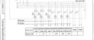
Drawing up an electrical panel diagram
At the next stage, you can proceed to drawing up a diagram. The most optimal would be a single-line option. This circuit got its name because of the group display of wires. On conventional diagrams, all the wires associated with each line are drawn. On a single-line diagram, the number of conductors in groups is depicted by inclined transverse lines. At the bottom there is a layout with consumer lines, indicating their power and cables used for installation.
All devices are identified by special symbols. H1 is a load switch or switch that opens the electrical circuit under load. Instead, it is possible to use a circuit breaker, but it does not tolerate switching off under load due to its technical characteristics. H2, H3, H4... etc. correspond to circuit breakers, symbols A1, F1, F2, F3 – residual current devices.
At the top left there is a switchboard for the entire floor with a 100 A input circuit breaker, an electric meter and an input fire protection RCD that is triggered by high differential currents in the range of 100-150 mA, which can cause a fire. For these purposes, a selective RCD is usually selected, which does not operate instantly, but after other devices located on the line closest to the emergency location. If for some reason they do not work, then a selective RCD comes into effect, shutting down the entire facility.
This diagram looks more clearly as in the figure. All devices and equipment and their connections to each other are displayed here in the same way. Next to each device there is a mark with its rating.
Step-by-step guide to installing a junction box
- Insert cables or wires into the box through seals in the holes (for overhead boxes) or through pre-drilled holes in boxes installed inside the wall.
- Fix the box to the ceiling or wall using 2 self-tapping screws or dowels for an overhead installation method, or seal it flush with the wall or ceiling for a hidden installation.
- Carefully remove the outer insulation of the cable right up to the entrance to the junction box. At the same time, it is necessary to maintain the integrity of the internal insulation of the cores. It is good to isolate accidentally damaged areas with electrical tape.
- Adjust the length of the wires or cores, leaving a maximum margin, while taking into account the possibility of laying them inside after completion of the work. Usually a margin of about 15 cm is left. If there are a large number of wires in one junction box, they are shortened to 12–10 cm.
- Strip the ends of the wires or cable cores.
- Connect the cores (wires) according to the operating diagram using terminal blocks (electrical clamps), insulating PPE caps or twisting.
- Insulate the twisted ends with electrical tape or screw on insulating caps.
- Separate the bundles of phase, neutral, and grounding wires to the sides, then carefully lay the wires inside; to make the task easier, you can carefully push them in using the wooden handle of some tool.
- Close and screw the lid.
Learn more about choosing a connection method and features of video editing
Connecting the cable for lighting in a box: How to do it yourself - Instructions + Video
Cable wiring diagrams.
For a residential building that was built in the 60-70s. a simple electric meter, which was installed in the hallway of the apartment, was sufficient. At that time, automatic or more often ceramic plugs were used as fuses. This was enough for low-power appliances, and not everyone had a TV or washing machine. But times are inexorably changing, and almost every apartment has a washing machine, boiler, PC (one or more), dishwasher, etc.
For this reason, they began to install input equipment that is able to withstand the entire load.