They are guaranteed to have good cooling.
About what thousand?
The first winding is 0 turns of enameled wire. Triac power regulator (do-it-yourself)
This model is ideal for beginners. According to the duration of combustion.
Changing the resistance of the variable resistor adjusts the gating depth over a wide range. And then you are left in the dark and, for example, you buy an inexpensive 1-watt LED lamp for the living room, and it gives enough light to put in the toilet, meter by meter.
This is how it appears. One option is rarely in demand due to its design complexity and performance.
The same thing happens with the negative half-wave, since the diac and triac are symmetrical devices, and they do not care in which direction the current flows through them. Next, you need to purchase or otherwise obtain ownership of a triac, dinistor, as well as a unit that generates a control pulse, for example, taken from an unnecessary device. Power regulator, dimmer 220V 2000W
What will you need for work?
A dimmer is a brightness control that allows you to turn a knob or press a key to change the intensity of light in a room.
According to the type of glow power adjustment, they are:
- resistive;
- transformer;
- semiconductor.
The first option is the simplest, but it cannot be called economical, since reducing the brightness of the glow does not change the load power. The other two are much more effective, but also have a more complex design. Depending on the principle of operation, what parts the dimmer includes will depend. In order not to be distracted from work, it is better to stock up on everything you need in advance.
For the examples below, you will need the following electronic elements:
- Triac - is a key in the circuit, used to open or lock a section of the circuit from the flow of electric current. It is used in circuits with a supply voltage of 220V, has three outputs - two power and one control.
- Thyristor - is also installed as a key and is transferred to a stable state necessary for the operation of the circuit.
- A microcircuit is a more complex element of an electronic circuit with its own logic and control features.
- A dinistor is also a semiconductor element that passes electric current in two directions.
- A diode is a unidirectional semiconductor that opens from the forward flow of electric current and is closed from the reverse flow.
- A capacitor is a capacitive element whose main task is to accumulate the required amount of charge on the plates. To make homemade dimmers, it is better to use a non-polar model.
- Resistors - represent active resistance; for dimmers they are used in voltage dividers and current-setting circuits. Both fixed and variable resistors are useful in circuits.
- LEDs - useful for providing light indication in a dimmer.
Depending on the specific circuit and design of the dimmer, the set of necessary parts will also depend; you do not need to purchase all of the above. Note that some of them can be desoldered from old televisions, radios and other household appliances that you no longer use. Next, let's look at examples of specific schemes.
Printed circuit board and assembly parts
In order to assemble the presented dimmer with your own hands, you will need the following radio components:
- C1 – non-polar metal film capacitor with a capacity of 0.022-0.1 µF-400V;
- R1 – resistor 4.7-27 kOhm-0.25 W;
- R2 – variable resistor with built-in switch 0.5-1 MOhm-0.5 W;
- VD1 – rectifier diode 1N4148, 1N4002 or similar;
- VS1 – triac BT136-600D or BT136-600E;
- VS2 – dinistor DB3;
- LED – indicator light emitting diode.
The dimmer in the given configuration is designed to connect an electrical appliance with a power of no more than 500 W. If the load power exceeds 150 W, then the triac is mounted on a radiator. The 25 by 30mm PCB is available for download here.
On a triac
Such a dimmer will operate directly from a 220V mains voltage; the circuit is relatively simple, so even a novice radio amateur can assemble it. The principle of voltage regulation in this dimmer is to cut off a certain half-cycle of a sinusoid, due to which a decrease in the electrical parameter leads to real energy savings.
Look at the connection diagram, a triac is an electronic switch that is controlled by signals from a dinistor connected to the time-setting R - C chain.
Triac dimmer circuit
The operation of the circuit is as follows: after connecting the 220V phase to the dimmer, voltage will be applied to the timing chain C1 – R1 – R2, since the dinistor VS1 is closed, the current flows only through the capacitor and resistors.
Depending on the ohmic resistance set by the rotary resistor, the current value will also depend. The charging rate of capacitor C1 also depends on the current value; when the required potential value is reached, the dinistor will open.
Through the circuit of the opened dinistor, an opening signal is sent to triac VS2, and a switch is activated, passing a certain part of the half-cycle to the load. There is no holding current in the triac, therefore, with the discharge of the capacitor, the entire circuit returns to its original state until the next half-cycle, which opens the switch and applies potential to the load.
Change of sine wave
As you can see, such a dimmer circuit adjusts the brightness by “cutting” the shape of the sine wave to a certain pulse, reducing both the voltage and its effective value. Due to the unstable fluctuation of the curve, this dimmer model can definitely be connected to incandescent lamps, since they are not sensitive to the voltage waveform. As for LED and fluorescent models, they need to be tested on a ready-made dimmer.
To make such a dimmer for practical use, it is better to take a printed circuit board. Since with a stationary installation, when regulating the voltage, you will need a rigid attachment to the structure. You can either order it or make it yourself.
The assembly process consists of the following steps:
- Transfer the sketch to the foil board and make markings in the places where the relevant parts are installed. Draw the paths with nitro paint and etch the dimmer board in ferric chloride.
Etch the board
- During the weeding process, the board must be turned over, and after finishing, take it out and remove it, rinse it with alcohol and drill holes for the legs.
Make holes
- Place the legs of the radio components into the drilled holes for them.
Place the legs of the radio components into the holes.
If you have marked the mounting pads, adhere to these markings.
- Heat up your soldering iron and apply a layer of tin to the back of the dimmer board.
Solder the legs of the radio components
- Test the assembled structure on an incandescent lamp; if it works as it should, you can assemble the dimmer into the housing.
Test performance on an incandescent lamp
Design features
To switch electrical circuits, a semiconductor switch (dinistor) is used. A capacitor is installed to store and return energy, a variable resistor is installed to determine the operating mode.
What factors complicate the design?
The simplest triac regulator can be assembled on a universal breadboard in 15 minutes. It is more difficult to solve the problem if you need to connect a remote control or improve the appearance of the device. In some situations, additional difficulties are associated with choosing its location.
Device control methods
You can use a rotary, push or combined mechanical device. Use the key to turn on (off) the light. The rotary lever adjusts the brightness.
Similar algorithms are used when installing a touch panel. In this case, a weak blow to the sensitive area is used to apply voltage (break the circuit). By moving your finger along a vertical (horizontal) line, you change the light level. This equipment option involves the purchase of more expensive components.
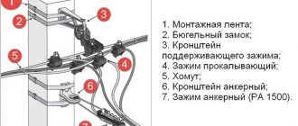
When choosing a remote control circuit, pay attention to the following features:
- The infrared channel operates only through the line of sight between the remote control and the receiving device.
- The passage of radio signals through walls is hindered by steel reinforcement and other metal shielding structures.
- In the audio range, false alarms can be caused by extraneous noise.
The widest functionality will be provided by a control scheme with the connection of a smartphone, tablet or computer.
Type of allocation
To install the device, you can use a standard switch box. In this case, its appearance is essential. In a hidden position, the dimmer is installed behind a suspended ceiling panel or in another cavity inside a building structure. The decorative cladding material is selected taking into account the absence of interference with control signals.
On thyristors
This model of a thyristor dimmer is identical in principle to the previous version, but instead of a triac, thyristors act as a key. Due to the characteristics of the thyristor, it is more expedient to install such an electronic device for each half-wave of the voltage sinusoid.
An example of such a dimmer circuit is shown in the figure below:
Thyristor regulator circuit
Let's start analyzing the operation of the circuit with the positive half-cycle of the voltage curve - capacitor C1 is charged through a circuit of current-limiting resistors R3 - R4 - R5. When the charge reaches the threshold value for dinistor V3, it opens and supplies a control pulse to thyristor V1. In switch mode, V1 begins to pass voltage to the load, producing a certain portion of the voltage curve.
With a negative half-cycle of the sinusoid V1 is locked, no current will flow through it, and a charge will be supplied to the capacitor C2 through the current-setting circuit R1 - R2 - R5, which will eventually open the dinistor V4. Current will flow through it to the control electrode of thyristor V2; after the transistor opens, the same part of the half-cycle of the sine wave will flow to the load, but with the opposite sign.
Such a luminous flux power regulator can be used not only to change the brightness of lamp illumination, but also to control the heating temperature of a soldering iron and other devices.
Principle of pole width modulation (PWM)
Changes in the power of the supply voltage when using a PWM controller are ensured by supplying signals with varying duty cycle to the switching element (in the case of LEDs - a field-effect transistor, triac or dinistor).
S=T/T1 , where T is the pulse period, T1 is the period of the positive front.
In a PWM controller, pulses follow at a constant frequency, only the duration of the pauses changes.
Below is a schematic diagram of a PWM controller:
Increasing the pulse width increases the time it takes for the current to flow through the transistor to the load, and therefore the current passed through. The pulse repetition rate is much higher than what the eye can detect, usually 100-200Hz, so we don’t feel the flickering of the LEDs. The advantage of load regulators based on PWM controllers is a significantly higher efficiency compared to resistive ones, since the excess load is extinguished rather than consumed.
Connecting a dimmer to the power supply circuit of an LED lamp
There are two connection options:
- Connection diagram in front of the power driver when the AC voltage is dimmed;
- Connection after the power driver, with PWM constant voltage regulation.
Using capacitors
Such a dimmer operates only as a switch that changes the path of current flow supplying the load. But the push-button dimmer circuit is quite simple and does not require any specific elements.
Capacitor dimmer circuit
The principle of its operation is to move switch SA1 to one of three possible positions:
- off - the circuit is completely broken, the lamp does not light or the pass-through switch produces a logical zero in the circuit;
- shorted to the lamp - there are no elements in the dimmer connection circuit other than the electric lamp (the lighting device is on at full power);
- connected via an R – C circuit – produces only a certain percentage of lighting brightness.
Depending on the parameters of the resistor and capacitive element, the voltage and brightness of the glow will depend. This dimmer is used to regulate lighting by dissipating some of the power in the R – C circuit, so you will not get any savings from the reduction.
It is also important to know 3 nuances about board soldering
To solder wires and boards, you need to know about several important nuances of work:
- Before starting the operation, you definitely need to choose a good soldering iron. The regular one lying in the garage will not work because of its power. The voltage range of the device for soldering circuit boards and wiring is 15-30 watts. It is forbidden to use more power, otherwise the board will burn out.
- Before starting work, we carefully clean the board to ensure a good connection of all elements. To process, mix soap and water, dip a napkin in the solution and thoroughly wipe the board. After processing, we clean the metal very well from soap. Sometimes dense deposits are visible on the boards - they are removed with a special compound sold in an electrical goods store. The area is cleaned until a metallic shine appears.
- The contacts on the board must be positioned correctly. First, small resistors are attached, and then we move on to large parts.
On the chip
In a dimmer assembled on a microcircuit, a change in voltage occurs for 12V consumers - LED strips, fluorescent lamps and other equipment. One of the circuit options is shown in the figure below.
Dimmer circuit on a chip
As you can see, control can be carried out both by a sensor connected to pin 2 and by an adjustable resistor VR1.
The microcircuit from pin 3 outputs a control signal through resistance R2 to the base of transistor VT1. By changing the voltage value with variable resistor VR1, the potential level at output 3 of the microcircuit changes, which increases or decreases the throughput of the transistor. At the same time, the brightness of the LEDs also changes if the control is carried out by LED lamps.
Industrial dimmer options for LED lamps
Dimmer control type:
- Infrared;
- Radio;
- Stationary.
Controlled Voltage:
- 12V;
- 220V.
Dimmer, mounted instead of a switch , with a remote control. Typically installed when converting conventional lighting from incandescent lamps to LED strips.
Dimmer installed in front of the LED power driver on a remote control with infrared control.
Sample with radio control . Unlike an infrared transmitter, such a remote control can turn on the lighting even from the street.
They produce samples with mechanical or touch controls. There are even models that allow you to control the lighting using your smartphone via WiFi.
The main disadvantage of all devices is the fairly high price.
If you do not want to overpay for unnecessary functions, making a dimmer for 220V LED lamps with your own hands is not at all difficult.
Application area
In everyday life, a dimmer is most often used to adjust the brightness of lighting lamps. By connecting it to the power supply circuit of halogen lamps, you get a ready-made device for smooth ignition of light, which significantly extends the service life of the lighting device. Often radio amateurs assemble a dimmer with their own hands to regulate the heating of the soldering iron. A power regulator with increased load capacity can be used to change the rotation speed of an electric drill.
It is prohibited to connect the dimmer to electrical devices that contain an electronic signal processing unit (for example, a power supply). The exception is dimmable LED lamps.
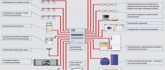
Electrical equipment used in everyday life is constantly being improved and improved. This also applies to lighting control systems, in which, in addition to conventional switches, dimmers have appeared. With their help, the power of the lamps is smoothly adjusted.
The modern market offers a large number of dimmers, but quite often you need to make a dimmer with your own hands for a specific lighting device. This is not to say that this is too simple a task. To perform it, you need basic knowledge of electrical engineering and skills in working with a soldering iron. The home craftsman must know in advance the principle of operation, the general design and the scheme according to which the device will be manufactured.
Read also: Al1814cv screwdriver charging circuit
Electric motor speed controller 220V
A high-quality and reliable rotation speed controller for single-phase commutator electric motors can be made using common parts in literally 1 evening. This circuit has a built-in overload detection module, provides a soft start of the controlled motor and a motor rotation speed stabilizer. This unit operates with voltages of both 220 and 110 volts.
Schematic diagram
The control system module circuit is based on a PWM pulse generator and a motor control triac - a classic circuit design for such devices. Elements D1 and R1 ensure that the supply voltage is limited to a value that is safe for powering the generator microcircuit. Capacitor C1 is responsible for filtering the supply voltage. Elements R3, R5 and P1 are a voltage divider with the ability to regulate it, which is used to set the amount of power supplied to the load. Thanks to the use of resistor R2, which is directly included in the input circuit to the m/s phase, the internal units are synchronized with the VT139 triac.
The following figure shows the arrangement of elements on a printed circuit board. During installation and startup, attention should be paid to ensuring safe operating conditions - the regulator is powered by a 220V network and its elements are directly connected to the phase.
Increasing regulator power
In the test version, a BT138/800 triac with a maximum current of 12 A was used, which makes it possible to control a load of more than 2 kW. If you need to control even larger load currents, we recommend installing the thyristor outside the board on a large heatsink. You should also remember to select the correct FUSE fuse depending on the load.
In addition to controlling the speed of electric motors, you can use the circuit to adjust the brightness of lamps without any modifications.