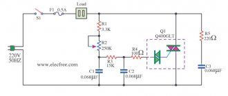
Supply and exhaust ventilation works by consuming and processing outside air. In conditions of negative temperatures and long winters, the air flows must be heated, because if you let them in directly, the microclimate inside the building will become unsuitable for humans. The supply air is heated by a heater. The efficiency of the ventilation system directly depends on it. Therefore, the piping of the supply air heater must be carried out in compliance with all norms and rules and only with high-quality materials. The technical part is being developed in the project.
Variants of typical solutions for piping steam equipment
Today, various equipment is used to install steam heaters. Depending on what it will be, completely different patterns and piping knots are used.
Special heater steam piping system for condensate removal:
Typical steam equipment piping.
- 3 shut-off valves, which are installed at the inlet, outlet and in the middle;
- thermodynamic diverter, which has a valve and a built-in filter to protect the system;
- sight glass for periodic inspection;
- check valve;
- special drain pipe for condensate;
- condensate drain;
- condensate line
The minimum length of the common condensate drainage unit for a steam heater is 1 m.
Collector piping.
If it is necessary to connect several points, then the use of a steam manifold with drainage is required. The diagram includes the following nodes:
- 3 shut-off valves (at the beginning, end and middle for adjustment);
- pressure gauge for pressure control;
- viewing window for system monitoring;
- float drain for condensate, which has a built-in filter and valve to protect the system from contamination;
- check valve
Steam reduction unit with pilot control.
Such a unit is necessary for generating steam; it includes:
Steam reduction unit.
- shut-off valves;
- several pressure gauges to control pressure in different areas;
- filters that are designed to work for 3-9 hours;
- pressure reducing valves designed to control the system;
- check valve;
- viewing window for monitoring the system and its condition;
- blast safety valve;
- special drain pan for collecting condensate;
- conclusion;
- drain pipe.
The length for such a system unit cannot be less than 10 diameters of the steam line; in some cases, a built-in impulse tube is provided.
How is the heating of the heater regulated?
In order to control the heating procedure occurring in the device piping unit, you can use one of two possible methods:
- quantitative;
- quality.
If you choose quantitative control of the system’s operation, then you will face an inevitable and constantly “jumping” coolant consumption. Such a method can hardly be called rational, and this is one of the reasons that in recent years people have more often resorted to another principle of control - qualitative. Thanks to it, it became possible to regulate the operation of the heater, but the amount of coolant does not change at all.
In addition, if you regulate the system using the quality principle, then the control is guaranteed to remain linear, regardless of what position the control valve is in.
Important! Quality control has one more advantage - this way the heater will be maximally protected from possible freezing, since water will constantly flow into it.
All this became possible only due to the fact that a water pump is installed in the heater circuit. There is a flow of water in the circuit, which will not depend on any external influences. In addition, quality control involves the use of a three-stroke rod valve and a specialized pump. All these parts built into the device’s piping have significant advantages that increase the efficiency of the heater and the entire system as a whole:
- The regulation valve is located in the place where the coolant enters the heater. If you compare this to a two-stroke device, it controls the entire mixing procedure. If the circuit is in a closed state, then internal circulation occurs; if it is open, then the coolant does not recirculate. If such a design is installed with a rod, this will not only increase the service life of the valve itself (which, as is known, very quickly becomes unusable in products that do not have rods), but will also increase heat transfer.
- The motor of a centrifugal circulation pump is “wet”; in other words, it operates while completely immersed in water. Consequently, the bearings of the device, as well as other elements, are constantly lubricated with water, so there is no need to use any kind of seals. If the heater piping is equipped with such a pump, then leakage is completely eliminated even in cases where the pump is broken or has completely exhausted its service life.
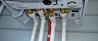
Heater steam distribution unit
The steam heater must be connected with a special distribution unit, that is, up to the supply point. This node includes:
Figure 2. Components for piping heaters of supply air systems.
- a special cyclone filter with condensate drainage, which also provides protection against contamination;
- pressure gauge to monitor the operation of the system;
- shut-off valves;
- safety valves;
- pressure regulators that provide pilot control;
- check valves;
- pressure reducing valves;
- special condensate discharges into the atmosphere.
The length of each steam supply section cannot be less than 10 steam line diameters. For each outlet, a shut-off valve and a pressure gauge for each section are installed at the steam supply point. The diagram of the strapping unit is shown in Fig. 2.
DIY ventilation
Having a ready-made project in hand, installing ventilation in a private house yourself is not so difficult. Ventilation ducts are assembled from corrugated pipes or individual metal or PVC elements of rectangular cross-section. All this just needs to be put together as a constructor.
To simplify the installation of air ducts, the following are now available:
- channels of different lengths and sections;
- a variety of connectors with and without built-in valves;
- knees with different rotation angles;
- tees and transitions;
- vent grates;
- holders and hangers.
All this must be connected to each other and to a ventilation unit, duct fan or recuperator. There should be a minimum of difficulties.
Ventilation diagram in a private house
Installation is carried out step by step in the following order:
- The holes in the walls and partitions are marked, where the ventilation ducts will run according to the plan.
- The centerlines of future air ducts are drawn on the walls and ceiling, indicating turns and branches.
- The installation location of the ventilation unit is marked (for a forced system).
- Drilling of walls is carried out, as well as fastening of suspensions and brackets.
- The channels are cut and connected to each other, the joints are fixed with self-tapping screws and the entire structure is subsequently secured to the holders.
- Ventilation lines are connected to the equipment.
- Diffusers and grilles are installed.
- The ventilation equipment is connected to the electrical network and the system is tested.
To protect air duct outlets from debris and precipitation on the street, caps, nets and deflectors are mounted on them. At the same time, outdoor sections of ventilation ducts, shafts and pipes are subject to insulation. If this is not done, then condensation will form in them, which will inevitably lead to problems.
It is not difficult to make ventilation in your cottage yourself. If you have a project with a specification of the required materials and a plan, then there should not be any special difficulties.
The main thing when completing the work is not to forget to install decorative inserts on the façade at the outlets of the ventilation ducts. Otherwise, even in photos of houses with siding or other exterior decoration taken from afar, these places look unsightly. A small detail not completed at the end, but it greatly spoils the overall appearance.
See also a video on how to make ventilation in a private house:
Read about our other materials:
Roofing felt: roll sizes and characteristics
Frame houses: pros and cons of frame construction
Heater connection diagrams
The heater has one task - heating the incoming air masses, with the ability to adjust the temperature of the coolant. There are several installation schemes:
- One ventilation circuit, one heater. The simplest scheme is when a single copy of the device is installed at the entrance or any other point of the ventilation duct. Suitable for seasonal heating. There is no backup heat source.
- Two ventilation circuits, several heaters. A more complex scheme, with numerous strapping nodes. The first circuit with its channel heating elements operates in the autumn-winter period, the second - in the summer. The double scheme is applicable for large buildings that require heating all year round. Allows you to safely pass through peak frosts by turning on both heating circuits.
Types of duct heating systems
There are three types of heaters and differ in the type of coolant. Each type has its own specifics of work and scope of application:
- Electrical. Household heating installations. Metal heating elements are heated by electricity. Installation is simple, without installing a complex strapping unit. The power is enough to cover a room of up to 100 m2.
Electric heater
- Mermen. They work on water circulating through tubes. A common option in ventilation systems of public and industrial buildings. For effective operation, installation of a strapping unit is required.
Water heater
- Steam. They are characterized by high efficiency, heating rate, and air exchange rate. The coolant is water vapor heated to the design temperature. Steam heaters are installed in ventilation systems of industrial enterprises where there is a source of water vapor.
Steam heater
Harness knots
They supply coolant to the heater and provide control over the temperature and pressure in the system.
Composition of the node diagram
Scheme of operation using the example of a water heater.
The classic scheme of the piping unit includes:
- Circulation pump.
- Compressor-condensing unit (KKB). It is used in piping cooling systems as an external unit. Connects to coolers of supply ventilation units or duct air conditioners.
- Devices for monitoring basic parameters: temperature and pressure.
- Shut-off valves.
- Bypass.
- Filter for cleaning incoming air masses.
- Automatic valve. There are two-way and three-way.
- Pipes and fittings.
The piping unit can be connected to the system using a rigid or flexible connection:
- Hard eyeliner. A simple connection option using metal pipes. It is practiced when the installation location of the heater is known and prepared in advance.
- Flexible eyeliner. A more complex connection option. Flexible corrugated hoses are used. It is practiced when the heater is installed in an unprepared place.
Heating adjustment
Designers distinguish two ways to regulate the temperature of a duct heater: quantitative and qualitative.
- Quantitative. An outdated method of adjustment. The temperature is directly dependent on the volume of the coolant; for this purpose, a two-way valve is installed in the piping system. The method is recognized as not rational, since the volume of coolant consumed is constantly “jumping”.
- Qualitative. More efficient way. At any position of the control valve, the coolant is consumed according to a linear principle. Linearity is ensured by a three-way stem valve and pump. The pump cuts directly into the heater circuit, its rotor rotates in a liquid medium. There is no need for seals and leaks are completely eliminated.
A three-way valve with a stem is installed at the entry point. If it is closed, then water circulates in a closed circuit. In the open state, the possibility of recirculation is excluded, since the backflow is prevented by the check valve.
Classification of power control options for installations
Scheme No. 1
The supply ventilation heat supply system can operate in several fundamentally different control modes:
- If during the operation of ventilation systems there is a smooth or stepwise change in water temperature at a constant flow rate, then it is customary to say that high-quality regulation is used at this unit. It is used in boiler houses or in individual heating points, that is, changes in coolant parameters will occur directly throughout the entire heat supply system. The hot water temperature is adjusted according to a special schedule of the heat supply organization depending on changes in the outside air temperature.
- If a change in the heat load occurs when the amount of coolant entering the installation changes, that is, at a constant temperature, the flow of hot water changes smoothly. Here we are dealing with quantitative regulation.
- With the qualitative-quantitative control method, temperature adjustments occur in the heating system (or from a heat source) and coolant flow changes zonally at each installation in its own mode. A rather complex control method, but most widely used in ventilation heat supply systems. It can only be implemented when installing an automation system.
Types of thermal energy consumption systems
There may be several such systems compatible with the heater. Let's look briefly at each.
Ventilation system
It is characterized by the fact that the maximum temperature of the coolant is directly influenced by the technical parameters of the existing equipment. The problem with regards to how to choose the right piping unit is the need to protect the heater from possible freezing. In winter, when the air is supplied at sub-zero temperatures, the temperature of the coolant cannot be reduced or the energy consumption lower than what the system requires.
Radiator heating
In this case, the coolant temperature is strictly limited. For single-pipe structures it is 105 degrees, for two-pipe structures it is 95 degrees. But the temperature of the carrier can decrease indefinitely, until the operation stops altogether, which distinguishes heating from a ventilation system. Here, all elements are in direct contact with the air in the building, and due to the fact that it also has heat-storing characteristics, the building cools quite slowly. In this case, the time period during which a decrease in temperature is possible is established for each individual case.
Underfloor heating
The heat consumption here is the same as in the previous version. The only difference can be considered that the temperature of the coolant (maximum) is limited. In most cases this is no more than 50 degrees.
Thermal curtain
The heater piping for thermal curtains differs significantly from all previous options, so we will consider it in more detail. First of all, this relates to the peculiarities of the operation of the thermal curtain itself: almost all the time the curtain “rests”, waits, but its working time often does not exceed two to three minutes. Moreover, the installation site is always located far from the heating source. In most cases, this is a place under the ceiling, and there, accordingly, hypothermia often occurs, as well as drafts. Below is a diagram with adjustment elements that are suitable for this case.
The system is equipped with special ball joints necessary to disconnect it from the described curtain or from the thermal route. There is also a coarsely cleanable filter that protects the device; an adjustment valve that prevents the entry of solid particles, which, in turn, can extremely negatively affect the performance of the system in general. There are two more valves:
- Regulating-shut-off.
- Regulating, equipped with a special drive.
Each of them is designed to provide maximum fluid flow in operating mode, and minimum flow when “inactive”. In order for the valve drives of such a piping intended for thermal curtains to be provided with proper power, a single-phase voltage of 220 volts should be connected.
Finally, all the elements that make up the heater piping in this case are necessary not only to regulate the temperature in the building, but to protect the device itself from temperature changes and pressure “jumps” that often occur in the heating supply network. If you install mixer blocks, the heating circuit will reach the operating mode that is necessary for the controlled parameters.
Note! Ventilation works more efficiently in this regard, since less energy is consumed.
Protection of heaters from defrosting. Coolants in ventilation systems
The number and purpose of air heaters in supply ventilation installations may vary depending on the composition of the installation and the purpose of its operation. The heaters can be of first heating, second heating, with preheating in front of plate recuperators, separate for operation at different times of the year, or used for heating on separate branches of air ducts if the temperature conditions of the served premises are different.
Therefore, it is customary to say that preheating or 1st stage heaters always operate on “hot” air. That is, air with a very low temperature enters the heaters. In a continental climate, the danger of heaters defrosting is very high when starting up installations in winter or during new construction, when there are frequent interruptions in the power supply and interruptions in the supply of hot water.
There can be a huge number of reasons for water freezing in heaters in winter: from accidental closing of the valve at the inlet to a failure in the power supply and automation systems. Also, the most common cause of defrosting is the incorrect choice of circuit, low pressure drop in the heating system, incorrect selection of the control valve and a drive with a long response time.
Defrosted heater of the supply ventilation system
You should also know that the ideal choice for controlling control valves is an actuator with analog control using a 0-10V signal. An equally rare cause of system defrosting is uncoordinated operation of the supply and exhaust ventilation systems. For example, it is a common case that during non-working hours the air supply units are switched off, but the exhaust units continue to operate for some reason, and a vacuum of air is created in the building. To replenish the air balance, air begins to be sucked in through all available leaks, including through a leaky air damper. Thus, when the system’s automation and insensitive sensors are turned off, the signal about low temperatures does not issue a command for the automation to turn on the heating of the heating system and the water in the heat exchanger freezes.
Video on defrosting the heater of the supply ventilation system:
Of course, heater piping units must also be equipped with the required number of sensors and protective thermostats complete with control cabinets, but in the event of power surges or lack of power supply, the automation system will not be able to protect the heaters. The only option to protect the system from defrosting with a 100% guarantee is to fill it with low-freezing coolants.
The main advantages of antifreeze include a low crystallization temperature and the absence of thermal expansion in a frozen state, which does not lead to rupture of the walls of air heaters. Low-freezing liquids include sets of additives that protect the pipeline system from corrosion, minimize cavitation and prevent sediment from forming when the system heats up or cools down.
The use of low-temperature coolants in some heat supply systems is limited by a maximum maximum temperature of 95-100°C, above which the chemical composition will decompose. Therefore, in an individual heating point, a temperature regulator or valve should be installed on the media separation heat exchanger (water-NZT), which will protect the heating system circuit from increasing the temperature above the critical one.
In heat supply systems, as a rule, ethylene glycol or propylene-glycol mixtures are used, which differ in both price and scope. Ethylene glycol is the cheapest coolant, therefore it is most widely used in engineering systems. Propylene-glycol mixtures are used in safe industries, where in the event of system depressurization, a toxic coolant can pose a potential threat to life or disrupt the technological cycle. Such requirements are found mainly in the food industry or in medical institutions.
A low-freezing coolant with a crystallization temperature of -30°C contains 40% ethylene glycol mixed with distilled water. The main feature of all ethylene glycol-based coolants is the formation of a plastic gel at low temperatures, which does not cause rupture of heater tubes or the formation of cracks in welded joints.
It is not recommended to use a low-freezing coolant with a crystallization temperature of _65 degrees in heat supply systems, but it should be diluted with water to the required concentration.
After filling the networks with ethylene glycol solutions, the system should be carefully pressurized, since it is most likely that small coolant leaks or leaks may occur at the threaded connections. This is due to the low surface tension of all coolants and the ability to penetrate into all cracks and leaks in the system.
When carrying out a hydraulic calculation of a heating system that will be filled with an ethylene glycol solution, it should be taken into account that the coolant flow rate will be 8% higher than the water flow rate, and the pressure of the pumping equipment should be increased on average by 54%. When selecting the diameters of pipeline sections, it is necessary to take into account the increased viscosity of coolants and introduce a correction for an increase in diameter, where necessary.
Water heater calculation
Calculation of the heater power required to heat a particular room is carried out taking into account such data as:
- The volume (mass) of supply air that needs to be heated.
- Initial (external) temperature of air masses.
- The target temperature to which the air must be heated before being supplied to the room.
- Temperature regime of the coolant.
The heater is calculated based on the heating surface area and the required power. Each operation has its own formula. The heater power can be calculated only taking into account real data in specific conditions, among which the most important are:
- connection method (to the central heating network or boiler room);
- strapping method.
Calculation of heater power
Qt – heater heat power, W; L – air flow, m³/hour ρair – air density. The density of dry air at 15 °C at sea level is 1.225 kg/m³; air – specific heat capacity of air equal to 1 kJ/(kg∙K)=0.24 kcal/(kg∙°C); tin – air temperature at the outlet of the heater, °C; tnar – outside air temperature, °C (air temperature of the coldest five-day period with a probability of 0.92 according to SP 131.13330.2012)
Heater power calculator
Air flow, m³/hour: Air density, kg/m³: Specific heat capacity of air, kJ/(kg × K): Air temperature at the air heater outlet, °C: Outside air temperature, °C:
Coolant consumption per heater
G—water consumption for heating the air heater, kg/h; 3.6 - conversion factor W to kJ/h (to obtain flow rate in kg/h); Qt – heater heat power, W; sv – specific heat capacity of water equal to 4.187 kJ/(kg∙K)=1 kcal/(kg∙°C); tpr – coolant temperature (straight line), °C; trev – coolant temperature (return line), °C.
Coolant flow calculator for heater
Thermal power of the air heater, W: Specific heat capacity, kJ/(kg × K): Coolant temperature (forward line), °C: Coolant temperature (return line), °C:
Air heating process diagram
You can determine the required heater power using special diagrams. The amount of energy required (Joules) to heat 1 kilogram of air is produced using the i-d diagram of moist air. The calculation is made under the condition that the air heating process occurs at d = const (with constant moisture content). Next, taking into account the calculated air flow rate and the conversion of units (J/s to kW), the heater power is determined.
i–d diagram of humid air
To obtain accurate data, you can use online calculators, with which you can find out the power indicator by indicating performance and temperature. Since the performance of the installation may decrease as a result of gradual wear, it is recommended to include a power reserve of 5 to 15% in the calculation.
Methods for organizing air exchange in the house
There are different ways to ensure air exchange in a residential building - from periodically briefly opening doors and windows to installing multifunctional systems for preparing and delivering clean air to each room.
From the point of view of ventilation, a healthy and comfortable atmosphere in the house is formed not only due to the composition of the air. Its temperature, uniformity of distribution and mobility play an important role.
The influx of cool air can create a powerful convection current, which will be perceived by humans as an unpleasant draft. As a result, even at normal temperatures the room will be uncomfortable.
In old brick buildings, ventilation and aeration were provided by special vents left during the construction of a residential building
The ventilation system in the cottage kitchen, made from wooden beams, also seemed as simple as possible. Leaky doorways and window blocks contributed to the continuous circulation of air currents in the house.
All these methods are still used today in small one-story buildings. There is quite enough natural air ventilation there. But if we talk about large and spacious private houses, then it is impossible to do without additionally installed central air conditioners and fans.
Advantages and disadvantages of water heaters
A water heater for fresh air ventilation has significant disadvantages that limit its use in residential premises:
- large dimensions;
- difficulty connecting to a common hot water supply system;
- the need for strict control of the temperature of the coolant in the water supply system.
However, to create a comfortable temperature in large premises (production workshops, greenhouses, shopping centers), the use of such heating systems is the most convenient, efficient, and economical.
The water heater does not load the electrical network, its breakdown will not cause a fire - these factors make the equipment safe to use.
Principle of operation
A fan, a heat exchanger and a convector - this is what a water heating device looks like in general terms.
The operating principle of supply ventilation is as follows:
- The air flow enters special air intake grilles that prevent insects, small objects, birds, and animals from entering the ventilation channels.
- Filters clean the air from contaminants, harmful substances, and dust.
- The heater, using heat supplied from the water main, heats it to the desired temperature.
- The recuperator mixes the newly supplied air with the heated one.
- The fan supplies heated air masses into the room, and the diffuser distributes them evenly over the entire area.
- Sound absorbers reduce the sound power of a running installation.
- If the air supply is cut off, valves are activated to prevent cold air from entering the room.
An example of using a VOLCANO air heater in a tire shop (water temperature +90 ºС)
The heater, which does not have its own heater, consists of two main elements:
- A heat exchanger, the design of which is represented by a system of metal tubes - water coming from the general heating system reaches the required temperature here.
- Built-in fan that disperses heated air flow throughout the entire area.
Basic equipment of heat supply units. Selection and calculation
The heat supply units of air handling units made according to different schemes, as a rule, include identical equipment. Such units differ only in the installation location, the saturation of the reinforcement and the selection method.
When selecting equipment for heat supply units, there are several general rules and recommendations:
- When choosing a particular type of valve, you should carefully check the technical characteristics of both the maximum operating pressure and the maximum temperature.
- It is highly not recommended to purchase ready-made mixing units that are selected based on average conditions without taking into account important parameters such as free pressure drop in the system, type of coolant, flow rate, type of heat source, the need for frequency regulation, and so on.
- The diameter of shut-off valves, as well as check valves and mud traps must be no less than the diameter of the pipelines.
- The diameter of the heating system pipelines is determined as a result of hydraulic calculation based on the calculated (required) coolant flow rate, type of coolant (water or low-freezing liquids) and pipeline material. In no case should the diameter of the heating supply units be selected based on the connecting ports of the heater. It is selected ONLY BY CALCULATION!
Shut-off valves
It is necessary to shut off the water flow in cases of emergency stops of the heating system, for example, to eliminate a leak, to carry out service or inspection work, etc. As shut-off valves, steel or brass ball valves (preferably full bore) or flanged valves are used.
For heat supply units with a pipeline diameter of up to 40 mm inclusive, it is customary to install threaded shut-off valves, and flanged valves over 50 mm.
To facilitate the installation or dismantling of assemblies, threaded fittings should be provided with union nuts, otherwise called “American or socket nuts”.
Check valves
Check valves are used in control units to prevent water from flowing back into the heating system if control valves are opened or closed. Or this is possible when the heating system is not balanced, a large number of units are installed in the system and when the coolant flow changes, pressure may occur on each other. Therefore, check valves are installed on the return pipeline and on the jumper of the heating supply unit.
Control Valves and Actuators
Two way valve.
A two-way or three-way control valve is the main actuator, which, by changing the flow rate or by mixing coolants, allows you to regulate the power of the air-handling unit heater depending on the heating demand of the installation. Another important function of the valve is to prevent the coolant from “freezing” when the units operate in winter. When the automation receives a signal about the critical temperatures of the coolant and air after the heater, the drive opens the control valve to the maximum flow.
Three-way valve.
The valve is selected based on the determination of the throughput coefficient Kv, which means how much coolant flow will pass through the valve in the open state with a loss of 10 meters of water column.
,
where G is the estimated water flow, m3/h; ∆p - actual pressure drop across the valve, bar Ƥ - coolant density.
The size of the control valve cannot be selected according to the diameter of the pipeline or heater ports. The smaller the Kv or valve diameter, the higher the speed of response to changes in air or heating network parameters will be, that is, the system will not be inertial.
In heat supply systems of air supply units, as a rule, two and three-way valves are used. Two-way valves work only in systems with changes in coolant flow, and three-way valves either act as mixing valves or work to separate heat flows.
Measuring fittings: pressure gauges and thermometers
Measuring equipment
Pressure gauges and thermometers are necessary tools for visual monitoring of the performance of the heating system. Thermometers are usually installed on the supply and return pipelines directly next to the heater. Pressure gauges are mounted on the pump group to monitor the operation of the pump and visually determine the difference created. Pressure gauges are also installed before and after the sump tank - to determine the degree of its clogging, and on the supply and return pipelines of the heating network in front of the piping unit - to control the free drop necessary for the full operation of the control valve.
Air bleed valves and system drain taps
Automatic air release valve
To bleed air after filling the system and during operation, it is recommended to install automatic air bleed valves in the piping units. They are conveniently mounted on special ports embedded in the heater coils in the upper part of the housing or at the highest point of the control unit pipelines.
Taps for emptying heaters and draining a section of the heating system should be installed at the lowest point of the control unit, or at the bottom of the heater.
Balancing valves
Balancing valve
If the heat supply system has several air supply units operating in their own independent mode, then the heat flows in the pipelines will not be constant and may differ significantly from each other. To prevent pressure on each other from the coolant side, balancing valves are provided. Their main and main function is to throttle excess pressure and equalize the distribution of water flow between heaters in accordance with needs. Balancing valves installed on the return pipelines hydraulically link the heaters to each other.
The need to install control units
Supply ventilation system installations, in accordance with the basic requirements of regulatory documents, must supply fresh outside air, preheated to a certain temperature. The supply air temperature must correspond to the type of ventilated room in the case of general ventilation or the technological process in the case of any production cycle.
The principle of operation of the supply and exhaust ventilation system.
In addition, the air temperature must be constant regardless of the outside air temperature and adjustments to the coolant temperature schedule. That is, when it gets colder and the temperature outside decreases, heating networks, as a rule, increase the temperature of the coolant, and the air temperature at the outlet of the air handling unit must remain at a given level.
Consequently, the heat load during the heating period is not a constant value, and the coolant must be regulated. Otherwise, there will be excessive consumption of thermal energy, an increase in temperature and excessive overheating of the premises, which can adversely affect the well-being of people or the technological process.
The air is heated in air supply air heaters, the number of which may vary depending on the adopted heat supply scheme. The most common option is installations with one heater, but there can be two or more.
Heaters are designed to heat air in the supply and supply and exhaust ventilation systems.
For some institutions where air heating is also necessary during the transitional season, two separate circuits of the heat supply system are provided. One heater operates in spring and autumn, the second circuit in winter. In the event of extreme frosts, when the main heater cannot cope with the load, the second one can heat the air to a predetermined temperature.
Supply installation of ventilation system.
Also, one of the main advantages of this scheme is almost 100% redundancy of the heat transfer surface. In case of emergency situations when one heater fails or defrosts, the second heater will be connected to operation and will fully cope with the main function. Therefore, when calculating the installation, it is advisable to provide two identical heaters, with a surface corresponding to the maximum power of the two operating modes.
When calculating the air handling unit, you may encounter a situation where the selected heater in maximum mode will produce thermal power many times greater than the required one. This is due to the limited number of heater sizes available from the manufacturer. Therefore, in order to have a constant supply air temperature, it is necessary to install control units of the heat supply system on each heating circuit and at each installation. These units will be controlled by the automation system of all ventilation systems of the complex.
Brief overview of modern models
To get an impression of the brands and models of water heaters, let’s look at several devices from different manufacturers.
No. 1 – KSK air heaters
Heaters KSK-3, produced at the company T.S.T.
The model range of domestically produced KSK water heaters includes 2/3/4-row devices that differ in performance and size
Specifications:
- coolant temperature at the inlet (outlet) – +150 °C (+70 °C);
- inlet air temperature – from -20 °C;
- working pressure – 1.2 MPa;
- maximum temperature – +190 °C;
- service life – 11 years;
- working resource – 13,200 hours.
External parts are made of carbon steel, heating elements are made of aluminum.
No. 2 – Volcano fan heaters
The Volcano mini water fan heater is a compact device from the Polish brand Volcano, characterized by practicality and ergonomic design. The air flow direction is adjusted using controlled blinds.
One Volcano mini fan heater is capable of generating as much heat as a dozen conventional bimetallic radiators made up of ten sections
Specifications:
- power within the range - 3-20 kW;
- maximum productivity – 2000 m³/h;
- heat exchanger type – double row;
- protection class – IP 44;
- maximum coolant temperature – 120 °C;
- maximum working pressure – 1.6 MPa;
- internal volume of the heat exchanger – 1.12 l;
- guide blinds.
Volcano water fan heaters are designed to heat the air in domestic and industrial premises using water coolant.
No. 3 – Galletti AREO air heaters
Galletti AREO heater made in Italy.
Galletti AREO water heaters are capable of both heating the premises being treated and cooling the space in hot weather
The models are equipped with a fan, a copper-aluminum heat exchanger and a drainage tray.
Specifications:
- power in heating mode – from 8 kW to 130 kW;
- power in cooling mode – from 3 kW to 40 kW;
- water temperature – + 7°C +95 °C;
- air temperature – from 10°C to + 40°C;
- working pressure – 10 bar;
- number of fan speeds – 2/3;
- electrical safety class – IP 55;
- motor protection.
In addition to the devices of the listed brands, on the market of heaters and water air heaters you can find models of the following brands: Teplomash, 2VV, Fraccaro, Yahtec, Tecnoclima, Kroll, Pakole, Innovent, Remko, Zilon.
Why does a building need ventilation?
The use of modern materials and various external enclosing structures of a cottage/house in construction complicates the natural air exchange between rooms and the street, and sometimes even blocks it. Thanks to internal and external insulation and installed plastic windows, buildings become airtight.
Such measures help preserve heat and save energy resources, but greatly impede the flow of fresh air. To correct this typical situation, it is necessary to organize an effective air circulation system.
In a building, ventilation is needed so that fresh air regularly enters the bathroom, bedroom, living room and kitchen, not through open windows and doors, but through special devices - anemostats and air diffusers.
According to generally accepted sanitary and hygienic standards, a properly functioning ventilation system is a mandatory element of the engineering equipment of all residential buildings
A constant flow of air into the house will provide comfortable conditions for long-term living of people and maintenance of plants, as well as for the full functioning of all technical systems.
Ventilation is also necessary to maintain optimal environmental parameters for the safe operation of various building structures, wooden furniture and interior items.
The circulation of air flows must be organized not only in living rooms, but also in utility rooms - bathrooms and toilets, in the kitchen, in the boiler room and basement.
A high-quality ventilation system helps quickly remove excess moisture and heat. Along with the exhaust air, harmful microorganisms, accumulated dirt and dust are simultaneously removed from the premises.
Organizing the outflow of polluted air is a preventive measure in the difficult fight against fungus and mold
That is why it is important, even at the design stage of a residential building, to think through all the details of the utility network: make the ventilation in the kitchen more powerful than in other rooms, correctly select the functional elements of the ventilation system to ensure an optimal level of oxygen in the interior.
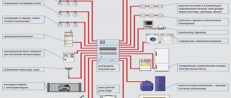
Components of forced ventilation
The supply and exhaust module is the main component of a forced-air ventilation system. The installation ensures normalized air circulation in a confined space - supply of clean flows and removal of waste materials.
The ventilation module is a complex of equipment enclosed in a single housing (monoblock unit) or assembled from prefabricated elements.
Diagram of the forced ventilation system: 1 – supply and exhaust module (PVU), 2 – air ducts, air intake grilles, adapters, 3 – air jet distributors, 4 – automation unit
The design of the supply and exhaust unit necessarily includes the following elements:
- Fan. Basic component for the operation of an artificial air exchange system. In PVU with an extensive network of air ducts, radial fans are installed to maintain high air pressure. In portable PES, the use of axial models is acceptable.
- Air valve. Installed behind the external grille and prevents the entry of air from outside when the system is turned off. If it is absent, cold streams will seep into the room in winter.
- Air ducts. The system uses two lines of channels: one is the supply, and the second is the exhaust of air. Both networks pass through the PES. The supply fan is connected to the first air duct, and the exhaust fan is connected to the second, respectively.
- Automation. The operation of the installation is regulated by a built-in automation system that responds to sensor readings and user-specified parameters.
- Filters. Complex filtration is used to clean the incoming masses. A coarse filter is placed at the inlet of the supply air duct; its task is to retain fluff, insects and dust particles.
The main purpose of primary cleaning is to protect the internal components of the system. For more “fine” filtration, a photocatalytic, carbon or other type of barrier is installed in front of the air distributors.
The device of a water heater using the example of the Vents VUT model with recovery and a heater. The design provides a bypass to protect the heat exchanger in winter
Some complexes are equipped with additional functionality: cooling, air conditioning, humidification, multi-stage air purification and ionization system.
Basic parameters for choosing a ventilation unit
The arrangement of an air circulation complex requires capital investment and considerable labor costs. Therefore, the approach to choosing the “heart” of the ventilation system is based on accurate calculations and analysis of a number of parameters.
Evaluation and calculation of technical characteristics
First of all, you need to decide on the appropriate capacity and static pressure values.
Performance. The calculation of the installation is based on air exchange standards according to SNiP, the purpose of the room, the service area and the number of residents.
It is necessary to perform two calculations (by the number of people and the air exchange rate), compare the indicators and select the largest value.
Air consumption standards per person: typical indicator - 60 cubic meters per hour, at rest - 30 cubic meters per hour. Regulated air exchange rate: 1-2 – for residential buildings, 2-3 – offices, shopping centers
An example of determining productivity (L) for a house under given conditions:
- number of family members – 3 people;
- house area – 70 sq.m;
- ceiling height – 3 m.
Formula 1. Calculation based on the number of residents.
L=N*norm
Where:
- N – number of residents;
- norm – air flow (not less than 40 cubic meters/h).
L=3*40=120 cubic meters/hour.
Formula 2. Calculation based on the air exchange rate.
L=S*H*n
Where:
- S – area;
- H – height;
- n – normalized air exchange rate.
L=70*3*1.5=315 cubic meters/hour.
Conclusion: to ensure sufficient air circulation, an installation with a capacity of at least 315 cubic meters per hour is required.
Typical indicators of ventilation units:
- 100-500 cubic meters/h – apartments and separate premises;
- 500-2000 cubic m/h – private households, cottages;
- 1000-10000 cubic meters/h – industrial buildings, workshops, offices.
Static pressure. The value indicates the pressure created by the fan to provide resistance to the air circulation path. Accurate calculation of static pressure requires taking into account the resistance of all network elements. “Manual” calculations are difficult to perform without appropriate experience. Specialists use a software package such as MagiCad.
Average pressure values at an air flow speed of 3-4 m/s: apartments 50-150 sq.m - 75-100 Pa, cottages 150-350 sq.m - 100-150 Pa
The given data is relevant specifically for modular ventilation units, and not for kit systems, where the pressure drop on the air valve, air heater, filter and other components must be taken into account.
In addition to the indicated parameters, you should evaluate:
- Energy efficiency. For each of the possible models, it is necessary to calculate the cost of electricity for 1 year, taking into account the operating mode in winter and summer. The energy consumption class indicates the ratio of energy expended to the volume of heat produced.
- Recuperator efficiency. It is necessary to compare the efficiency values in different operating modes of the PES. Heat exchangers with a double plate cassette and an intermediate zone have a high efficiency indicator - efficiency reaches 70-90%.
- Heater power. The typical figure for household ventilation units is 3-5 kW.
It is better to give preference to models with the ability to automatically reduce the fan speed to adjust the load on the network.
Noise level and degree of filtration
Acoustic power shows how “loud” the assembled installation will be. The sound effect is determined by two quantities:
- LwA – degree of acoustic power;
- LpA – sound pressure level.
The real “noisiness” should be assessed based on the first indicator. Different manufacturers may measure acoustic power using different methods, so the same values sometimes have different results in practice.
An effective method to evaluate the “sound” of an installation is to test the equipment in the showroom. The permissible noise level in a residential area is 25-45 dB
The quality of the incoming air depends on the cleaning system used. Possible filtration stages:
- barrier against coarse street dust, wool and fluff - rough cleaning with G4, G3 filters with an efficiency of 90%;
- protection against fine dust of 1 micron – filtration class F7-F9;
- absolute cleaning, providing a barrier against particles of 0.3 microns - HEPA filters (H10-H14), efficiency - 99.5%.
For residential buildings, the first two cleaning steps are sufficient. Highly efficient filtration is used in medical institutions, premises for the production of medicines, food, and electronics.
Ease of use: necessary functionality
Household PVUs are equipped with a built-in automation system, a control panel, and an LCD display displaying all air exchange parameters. In addition to basic options (adjusting fan speed, temperature), practical functions are welcome.
Timer. Scenario management will allow you to optimize the operating mode for a certain time of day or day of the week.
For precise adjustment, it is advisable to choose devices with a fan of 5 or more speeds, as well as a real-time clock that does not reset when the power is turned off.
Restart. The ability to automatically turn on and save set parameters in the event of a power failure.
Filter clogging indicator. A convenient option is notification about replacing the filter element. High-tech models are equipped with pressure change sensors at the air filter inlet - when dirty, the pressure drop increases.
Self-diagnosis. Any equipment breaks down over time. It is useful if the automation “notifies” about a malfunction - this will help to identify and fix the problem in a timely manner.
Duct heater for air ducts
In modern buildings, the ventilation system, as a rule, works in conjunction with the heating system of the building, and in some cases completely replaces it. To heat the air in ventilation systems, an air duct heater is used. Most air heaters in ventilation systems are water or electric. A water air heater is essentially a heat exchanger in which the air receives heat from hot water heated in a heating boiler or coming from the central heating network.
An electric duct heater is powered from the mains and converts electrical energy into heat. We always have heating ventilation available for sale: supply duct water heater, electric air heater, water air heater, electric drive and three-way valve for the heat exchanger.