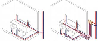
When connecting a cottage, correct distribution of the load across phases allows you to optimize the use of electricity, reduce the likelihood of overloads, breakdowns of electrical appliances due to inappropriate voltage, and even reduce meter readings. Let’s look at the possible nuances and look at several of the most popular schemes using illustrative examples.
Power supply for a cottage Source www.starling-k.ru
The need for three-phase connection
In a single-phase network, often the only phase is overloaded due to the use of powerful units , which are becoming more and more common in modern homes. As a result, connected electrical appliances fail, creating an emergency situation that threatens a fire.
At the entrance to the house there are always three phases, which are distributed in a phase-zero set. Pairs power groups of loads of equal power. If a residential building is allocated 15 kW of power, then each group receives no more than 5 kW. If the rule is not followed, the circuit breakers will trip if the line is overloaded.
If consumers in the house require a total of more than 15 kW, a three-phase connection is needed
Equipment requiring a three-phase line connection:
- an electric heating boiler in a large house can take about 9 kW;
- water pump operating in a deep well;
- electric stove for baths, high-power saunas (from 5 kW);
- hob, oven;
- equipment for a private workshop at home, for example, milling and lathes, a circular saw, a welding machine, a jackhammer.
Such units can be found with a 220V connection, but 380V is more reliable, more powerful, and more economical . Modern devices for everyday use can be designed specifically for 380V, for example, a motor on a garage door or entrance to a yard.
Three phases are needed if there are three-phase motors on the site that are not designed to operate in single-phase regulation. Alternatively, the organization of such input is necessary when many electrical appliances are used at the same time, for example, a household has been developed, private production has been established.
They try to supply a three-phase power line to every private building, and the user can use it or not as he wishes.
Pros and cons of three-phase connection
Economical use of electricity
Low material consumption of transformers and power cables
Even load distribution
Synchronous and asynchronous current motors show high efficiency
It is possible to obtain simultaneously linear and phase voltage in one installation
Probability of reducing lamp flicker and stroboscopic effect of fluorescent lamps
In the event of an accident, one or two phases burn out, but for power supply there is the possibility of a temporary backup connection
Three phases are required if there is not enough single phase line, but in this case it is easier to request an increase in the limit
It is necessary to distribute the load evenly between phases
A new switchboard and accessories are required
The danger of electric shock increases, since the network contains not only single-phase voltage, but also linear
Calculation of energy consumers
Before distributing the load across phases, it is recommended to perform a preliminary calculation of consumers. This can be easily done by making a list of potential sources that will be assigned to a particular phase. For example, list the main household appliances and their power as stated by the manufacturer:
- Electric hob 6.5-7.5 kW.
- Washing machine 1.5-1.8 kW.
- Dishwasher 1.5-1.8 kW.
- Microwave oven 0.9-1.2 kW.
- Oven 2.0-2.6 kW.
- Vacuum cleaner 1.9-2.2 kW.
- Iron 1.9-2.2 kW.
How to properly divide energy consumers into several groups Source uk-parkovaya.ru
Important! If necessary, the list can be supplemented with other electrical appliances on the balance sheet.
Requirements for connecting 380 volts
The rules for connecting the site are prescribed in the text of Federal Law No. 35 “On Electric Power Industry” dated March 26, 2003 (Articles 20 – 26), edited on December 27, 2019. The work of electric grid companies is regulated by Federal Law No. 135 “On the Protection of Competition” dated July 26, 2006.
Example specifications
Basic Rules:
- the user cannot independently connect electricity to the house; an energy supply organization is needed;
- connection is possible after fulfilling the requirements of the technical specifications;
- use cables with aluminum (not less than 16 mm²) or copper (not less than 10 mm²) conductors; armored cables are laid underground;
- with an aerial connection, the cable does not sag below the road below 6 m, above the sidewalks - below 3.5 m;
- the underground line is buried 0.7 - 1 m or lower;
- entry into the dwelling - not lower than 2.75 m from the ground;
- devices installed upstream of the electricity meter must be sealable.
In a 380V network, it is allowed to connect a three-phase meter in a private house with a maximum current strength of 50A, accuracy class - 2, last check - no more than 1 year ago. It is fixed on the DIN rail of the distribution panel, but it can be located outside the switchboard. The house must have a grounding system.
How to apply for a permit
The consumer has the right to connect to any electrical facility within 300 m from the site (power line supports, transformer substations, cable lines). The contract is concluded for a new connection, increasing power or moving the entry point.
List of project documents:
- site plan in the general layout of the development;
- connection diagram for power receivers;
- internal wiring diagram;
- PPR for connection.
The application is written at the company’s office, or submitted in your personal account through the website.
Information to be submitted with the application:
- Full name of the applicant;
- address of the connected site and the actual location of the user;
- project development period and commissioning time;
- power separation between phases;
- highest required power;
- type of load.
The company must meet deadlines for making decisions on the application. For individuals with a required power of up to 15 kW, this period is equal to 15 days, with other indicators or for a temporary connection - up to 30 days. After signing the contract, the specifications are given, which the user must exactly carry out on his site.
The owner notifies the company about the completion of preparation; in response, the electrical network checks the compliance of the specifications and the actual work in the presence of a representative of the supplier’s supply organization. A certificate of compliance is drawn up (within 3 days), the owner of the site signs the document within 5 days. This is followed by: an agreement on technological connection, an agreement on the supply of electricity. After this, 380V is supplied to the site.
Branch design features
Most often, a three-phase connection to a house on a power line is carried out by an overhead line, on which a short circuit or break may occur. To prevent them, you should pay attention to:
- the overall mechanical strength of the created structure
- quality of outer layer insulation
- current-carrying material
Modern self-supporting aluminum cables are lightweight and have good conductive properties. They are well suited for installing an air branch. With three-phase power supply to consumers, a SIP core cross-section of 16 mm2 will be sufficient for long-term production of 42 kW, and 25 mm2 - 53 kW.
When a branch is made using an underground cable, pay attention to:
- the configuration of the route being laid, its inaccessibility to damage by unauthorized people and machinery when working in the ground
- protection of ends coming out of the ground with metal pipes to a height no less than average human height
The best option is to completely place the cable in the pipe up to the entry into the control unit and the distribution cabinet.
For underground installation, use only a single piece of cable with strong armor tape or protect it with pipes or metal boxes. In this case, copper conductors are preferable to aluminum ones.
The technical aspects of three-phase connection of a private house in most cases require greater costs and effort than with a single-phase circuit.
Selection of materials and equipment
Input components and the meter are placed on the distribution panel, the dimensions of which are determined by the number of connection points. Metal boxes with protection from moisture are placed outside, steel and plastic cabinets are used inside.
Set of components for connection:
- corrugated tubes, self-extinguishing or non-flammable cable ducts;
- copper cable VVGng;
- three-phase meter;
- connecting switches: combs, buses, terminals;
- protective and safety fittings;
- automatic circuit breakers complete with RCDs or combined automatic circuit breakers;
- a relay that protects against voltage surges in the circuit.
A DIN rail is prepared for high-quality fastening of automatic machines and protective devices; mounting spaces for these devices are provided on the bar.
To carry out internal wiring , you need wires, boxes for changing the direction of wiring, socket boxes and for switches. You will need alabaster or plaster to fix the cables in the wall grooves, clamps, electrical tape, and adapters.
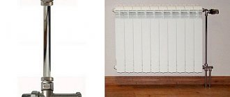
AV circuit breaker
A circuit breaker is a device that allows you to close and open electrical network contacts in both normal and abnormal conditions. The main purpose of the AV is protection against short circuits and overloads of electrical installations.
Depending on how many phases of the supply voltage are used in the electrical network of a private home, one-, two- and three-pole circuit breakers are used. It is advisable to use single-pole and three-pole switches for connecting phase wires, two-pole switches for switching neutral and phase wires. Two-pole circuit breakers provide one-time disconnection of these wires.
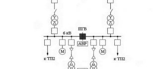
Input of three phases into the building and outgoing lines
Electricity from the pole is connected to the building through the air or underground.
All conductors are connected to the electrical panel, then the electric current enters the meter and passes to the distribution unit. Here the working zero and the grounding wire are separated, they are connected to the grounding bus, which is connected to the repeated grounding branch. Formation of outgoing lines :
- additional circuits come from the input switchboard (VRS);
- an introductory switch is installed in it, all phases are connected to it;
- circuit breakers are installed for each group circuit in the home, each of them is powered from different phases;
- groups are formed according to the power of units and devices so that each phase has approximately equal value;
- three phase conductors and a neutral conductor from the grounding bus are connected to the meter contacts;
- the meter output is connected to a common circuit breaker for the entire house.
Valera
The voice of the construction guru
Ask a Question
For connection, use the triangle or star method. The first method is to connect the phases sequentially: the end of the first to the beginning of the second, the end of the second to the beginning of the third, and so on. Star - when the ends of the phases are joined at a common point and the ends of the phases of consumer windings - also in one place.
Electricity input distribution device
It differs from a simple input device in that its design includes elements that distribute electricity among consumer groups inside the building. It is mounted at the electrical cable input in an extension or some separate room.
The ASU is installed inside a metal cabinet, where all three phases, a PEN conductor and a re-grounding circuit bus are connected in the building connection diagram using the TN-CS system.
Inside the input switchgear cabinet, the phase conductors are connected to the terminals of the input circuit breaker or power fuses, and the PEN conductor is connected to its busbar. Through it, it is split into PE and N with the formation of the main grounding bus and its connection to the repeated grounding loop.
Voltage increase limiters operate on a pulse principle, protect the circuit diagram of phases and working zero from the effects of possible penetration of extraneous external discharges, divert them through the PE conductor and the main protective bus with a ground loop to the ground potential.
When high-voltage pulse discharges of high power occur in the supply line and pass through a serial chain of a circuit breaker and an SPD, it is quite possible that the power contacts of the machine will fail due to burning and even welding.
Therefore, the protection of this chain with powerful fuses, carried out by simply burning out the fuse link, remains relevant and is widely used in practice.
A three-phase electric meter takes into account the power consumed. After this, the connected loads are distributed among consumption groups through properly selected circuit breakers and residual current devices. There may also be an additional RCD at the input, which performs fire-fighting functions for all electrical wiring of the building.
After each group of RCDs, consumers can be further divided by degree of protection with individual circuit breakers or dispensed with, as shown in different sections in the diagram.
Cables going to groups of end consumers are connected to the output terminals of the shield and protection.
Electrical panel assembly
The input switch and meter are sealed by power grid workers, so they are located at the beginning of the switchboard so as to provide this opportunity.
Step by step assembly:
- fastening of automatic devices and RCDs on the rail according to the drawn up diagram;
- connecting elements to the input switch using a comb;
- connecting phase wires with wires with lugs;
- installation and connection of the zero bus;
- checking (tightening) joints with a screwdriver;
- turning on the power, checking the operation of the machines;
- determining network parameters using a multimeter.
Before starting to operate the 380V network, make sure that all elements of the internal system (sockets, sockets, switches) are installed and connected.
How are three phases different from one?
In both types of power there is a working neutral conductor (ZERO). I talked in detail about protective grounding here; it is a broad topic. In relation to zero in all three phases - the voltage is 220 Volts. But in relation to these three phases to each other, they have 380 Volts.
Voltages in a three-phase system
This happens because the voltages (with active load, and current) on the three phase wires differ by a third of the cycle, i.e. at 120°.
You can read more in the electrical engineering textbook - about voltage and current in a three-phase network, and also see vector diagrams.
It turns out that if we have three-phase voltage, then we have three phase voltages of 220 V each. And single-phase consumers (and there are almost 100% of them in our homes) can be connected to any phase and zero. You just need to do this in such a way that the consumption in each phase is approximately the same, otherwise phase imbalance is possible.
Connecting sockets
The peculiarity of 380V sockets is that they block from asymmetrical connection to avoid short circuit. The contacts are placed at an angle, they are different in size, with guide elements.
Stationary 380V sockets are produced in the following types:
- 2P+PE has two power (phase) terminals and a grounding terminal;
- 3P+PE or 3P+N is characterized by three phase terminals and one for grounding connection;
- 3P+PE+N - there are places for connecting three phases, one for zero, one more for grounding.
The sockets are interlocked to prevent switching off under load. The current strength (25, 63, 125A) for which these sockets are made is significant, and the products do not have an arc-extinguishing effect. Removing plugs under such a load is dangerous in terms of burns or burnt out sockets. The lock can be of an electronic or mechanical type.
Sockets are connected to the power cable in series, parallel or in a mixed way.
The emergence of the three-phase voltage concept
Dolivo-Dobrovolsky is considered the father of three-phase voltage in Russia and Nikola Tesla in the rest of the world. Events relating to the era of the emergence of the subject of the dispute took place in the 80s of the 19th century. Nikola Tesla demonstrated the first two-phase motor while working for a company where he set up electrical installations for various purposes. Interest in the phenomenon of electrification of domestic cat fur led the scientist to great discoveries. While walking in the park with a friend, Nikola Tesla realized that he would be able to put into practice Arago’s theory of a rotating magnetic field, and he would need:
- Two phases.
- The shift between them is at an angle of 90 degrees.
To show the great significance of the discovery, we note that Yablochkov’s transformer did not gain mass popularity at the indicated time, and Faraday’s experiments on magnetic induction were safely forgotten, only the formula of the law was written down. The world didn't want to know about:
- alternating current;
- phase;
- reactive power.
Generators (alternators) and dynamos rectified the voltage using a mechanical commutator. The entire electricity industry, which was meager at that time, languished in a similar way. Edison was just beginning to invent; no one really knew about the incandescent light bulb yet. By the way, in the Russian Federation they believe that the device was invented by Lodygin.
Tesla's idea looked revolutionary; it remained unknown how to obtain two phases with a given interphase shift. The young scientist had little interest in the question. He read about the reversibility of electric machines and radiated confidence that he could easily build a generator by arranging the windings accordingly. There were no difficulties with the drive. At the beginning of the 80s, steam was actively used, the demonstration model was supposed to be powered by a dynamo.
3 phase image
Tesla did not set out to obtain a certain frequency. No research was carried out; it was simply necessary to make the rotor rotate. The idea was realized through slip rings. At that time, brushed DC motors were equipped with similar contacts; Tesla’s conclusion is not surprising. It is more interesting to explain the choice of the number of phases.
Electrician's recommendations
For hidden wiring, built-in electrical panels are chosen, and exposed wires are connected in overhead distribution panels. The shield body is placed so that it can be easily reached.
Electricians advise observing the following conditions:
- horizontal sections of wires from the panel to the sockets are made at a height of 2.5 m from the floor;
- wiring in the walls is placed vertically or horizontally; it is prohibited to install it along an oblique line;
- connect the wires with adapters in installation boxes;
- the underground connection to the power pole is made with a single piece of wire without connections;
- Do not connect the switch to the neutral wire;
- When laying on wooden walls, insulating hoses with asbestos linings are used.
The distribution housing is selected according to the type of room, taking into account the characteristics of the microclimate - in aggressive environments, boxes with maximum protection from direct water jets and dust are used.
Using an electric motor
You probably know that the rotor of a conventional three-phase motor, after starting, continues to rotate after one phase is disconnected. It turns out that there is an EMF between the terminal of the disconnected winding and the activated terminals.
The phase shift between the stator windings depends only on their location. In a three-phase motor, these coils are located at an angle of 120º, which means they provide the same phase shift angle. This circumstance suggests that an asynchronous three-phase motor can be used to obtain 380 volts from a conventional single-phase network. A simple diagram for connecting an electric motor is shown in Figure 3. The capacitor in the diagram is needed only to start the engine. Once launched, you can disable it. We take the capacitor type MBGO, MBGP, MBGT or K42-4, the operating voltage of which must be at least 600 V. You can use the capacitor K42-19, with an operating voltage of at least 250 V.
Electrical 380V electricity metering panel for a private house with a 220V socket
In this electrical panel diagram, there is additionally a modular 220V socket (number 7) with an individual protection device - difavtomat (number 8), which combines a circuit breaker and a residual current device. The rating of the RCD must be higher than that of the circuit breaker, for example 40A, leakage current 100 or 300 mA.
Electrical metering panel 380V, with modular socket, TN-CS grounding
Photo
Finally, a few more photos with comments.
Electrical panel with three-phase input, but all consumers are single-phase.
Three-phase input. Switch to a smaller cross-section of wires to connect them to the meter.
Friends, that’s all for today, good luck to everyone!
I look forward to your feedback and questions in the comments!