Connection of aluminum wires
How to connect two aluminum wires to each other? It would seem like a rather banal question, but even here the first answer that comes to mind is not always correct. After all, twisting of wires is prohibited according to the PUE standards, and any wires can be connected only by crimping, soldering, welding and using screw clamps. And we’ll talk about how to do it correctly in our article.
Types of cables for connection
The most common cable for home electrical wiring is a PVA connecting cable, consisting of two insulating layers. Copper strands, stranded, twisted along the central axis. The wire is flexible, making it great for a variety of connections. The voltage of connected devices must be up to 380 Volts.
The cross section is selected depending on the load:
- for a current of 6 A, PVA with a cross section of 0.75 mm is used;
- for 10 Amperes - the cross-section is 1 mm;
- for currents of 16 A – 1.5 mm.
In addition to the PVS wire, for connection there are multi-core cables ShVVP, PUGNP, PRS, KG. They are used less frequently for home wiring than PVS.
How to choose the right method
It all depends on the amount you can afford to spend, the power of the device that will be connected to this outlet, as well as the presence or absence of decoration on the walls (the desire and ability to ruin it).
In any case, the most reliable way to connect any outlet is a separate (parallel) connection directly to the main panel or distribution box in the room (if the cable cross-section allows). If the outlet is planned only for connecting a TV or similar not very powerful devices, then a daisy chain connection is also quite suitable.
If you plan to install wiring in a new house or modernize (replace) an old one in an apartment, then first of all you need to, without undue modesty, imagine what electrical appliances you would like to have - what can be connected to the network in principle. Based on this, it is already possible to calculate the required cross-section of wires and the method of connecting them.
Source
GOST classifications and requirements
Wire connectors are any devices that serve to close/open an electrical circuit. These can be electrical installation products - sockets, switches, as well as metal bars and plates, lugs, terminals and terminal blocks - blocks with several sockets.
We will focus on connectors in a narrower sense - on elements that create detachable and non-separable connections and ensure their reliability and functionality - that is, on all kinds of terminals, terminal blocks and sleeves.
The simplest example of a lug for a stranded wire. The terminal is a metal sleeve-tube fixed at the end of the conductor using crimping pliers
Terminals are called both metal elements for decorating the ends of single- and multi-core wires, and small plates inside connecting devices - sockets, terminal blocks, patch panels.
The terminals differ in material, shape and size, but are similar in purpose - they provide mechanically strong switching of two or more wires, without electrical losses and installation difficulties
The classification of electrical connectors is presented in GOST 10434-82 , which provides information on the division into classes (1, 2, 3) and groups (A, B). Also, according to standards, contact connections are divided into detachable and permanent, requiring stabilization or working without it.
Some recommendations may be useful not only to professionals, but also to home craftsmen who install their own electrical wiring.
For example, it talks about the most preferred methods of connecting aluminum plates - soldering or welding and aluminum tips - crimping or welding.
Branch to the house from VLI
From the VLI main line, two types of branches can be made to the house from the VLI.
- A linear branch is the connection of an additional VLI branch with more than two spans.
- The branch to the input is a section of the overhead line from the main line or linear branch to the house. More often it is called a subscriber branch.
The branch is made by air or trench (underground) method. A trench branch can only be made along the support downwards. In this article we will consider only the requirements for the air branch.
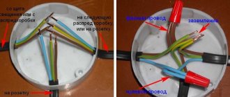
branch to the house from VLI: 1-support; 2- VU with a counter; 3-fastening SIP to the facade.
What is the best way to reliably connect two cables together?
Methods of connecting cables that require equipment and skills in the field of electrical engineering:
- soldering;
- welding;
- crimping with sleeves.
Simple connection methods that do not require tools or knowledge:
- connection using terminal blocks;
- spring clamps;
- PPE caps;
- bolted connection.
The choice of connection method depends on the characteristics of the wires. It is necessary to take into account the type and material of the core, the number of wires, and operating conditions.
Aluminum
Aluminum wires can also be connected using any method, but with some special features. When connecting, the metal must be manually stripped of insulation.
Copper and aluminum wires cannot be connected directly. The connection point becomes very hot and over time the contact weakens. Therefore, it is better to use terminal blocks, wago, bolt connection or special branch clamps.
Copper
Copper wire can be connected using terminal blocks, Wago clamps (necessarily using special paste), using a bolt, or soldering.
Alternative options
flat spring clamp
The wires can be connected to each other using a rivet. In principle, this technology is similar to screw technology, only here a rivet is used instead of a screw. The end result is a permanent connection.
This connection is made quite simply: both conductors are put on the rivet through a spring washer, then it is inserted into the rivet gun and the handles are pulled together until a click is heard.
There is also a special flat spring clamp. Such products are disposable and reusable, when the wire can be either inserted or removed. However, it should be remembered that such clamps are made of plastic, so it is not advisable to use them for currents exceeding 10 A.
Working with them is very simple: the wires are stripped and inserted into the clamp until they click. It is impossible to pull them out from there without using a special lever. It is also advisable to insulate this section of the wire.
Connecting electrical wires by twisting
Until recently, twisting was the most common method of connecting wires when doing electrical wiring; due to its accessibility, all it took was a knife and pliers. But, according to statistics, twisting is an unreliable way to connect conductors.
According to the electrical installation rules (PUE), twisted connections when installing electrical wiring are prohibited. But, despite the noted disadvantages, the twisting method is currently widely used. Connecting conductors of low-current circuits by twisting, subject to certain rules, is quite justified.
The photo on the left shows how twisting is unacceptable. If one conductor is twisted around another, the mechanical strength of such a connection will be insufficient. When twisting wires, you must make at least three turns of wires around each other. In the middle photo, the twisting is done correctly, but a copper conductor is twisted with an aluminum one, which is not permissible, since when copper comes into contact with aluminum, an emf of more than 0.6 mV occurs.
In the photo on the right, the twisting of copper and aluminum wires is done correctly, since the copper wire is tinned with solder before twisting. You can twist several wires together at once; in a junction box, sometimes up to 6 conductors are twisted, wires of different diameters and from different metals, a stranded wire with a single-core wire. Only the stranded wire needs to be made single-core by first soldering it with solder.
Electrochemical corrosion of joined metals
There is an opinion that it is unacceptable to connect aluminum and copper wires directly together and this is indeed a scientifically proven fact. Is it possible to connect a copper wire to a galvanized terminal? Of course, you cannot immediately give an answer, but in a minute you will be able to navigate this issue no worse than an experienced chemist.
What happens when two different current conductors come into contact? If there is no moisture, the connection will always be reliable. But there is always water vapor in the atmospheric air, which is the culprit for the destruction of contacts. Each current conductor has a certain electrochemical potential. This property of metals is widely used in technology, for example, thermocouples are made.
But if water gets between the metals, it forms a short-circuited galvanic cell, current begins to flow, and just as one of the electrodes is destroyed in the galvanic bath, so one of the metals in the connection is destroyed. The electrochemical potential of each conductive material is known, and knowing the value, you can accurately determine which materials can be connected to each other.
Table of electrochemical potentials (mV) arising between connected conductors
| Metal | Copper and its alloys | Lead-ol. solder | Aluminum | Duralumin | Steel | Stainless steel steel | Zinc coating | Chrome coating | Silver | Carbon (graphite) | Gold Platinum |
| Copper and its alloys | 0,00 | 0,25 | 0,65 | 0,35 | 0,45 | 0,10 | 0,85 | 0,20 | 0,25 | 0,35 | 0,40 |
| Lead-ol. solder | 0,25 | 0,00 | 0,40 | 0,10 | 0,20 | 0,15 | 0,60 | 0,05 | 0,50 | 0,60 | 0,65 |
| Aluminum | 0,65 | 0,40 | 0,00 | 0,30 | 0,20 | 0,55 | 0,20 | 0,45 | 0,90 | 1,00 | 1,05 |
| Duralumin | 0,35 | 0,10 | 0,30 | 0,00 | 0,10 | 0,25 | 0,50 | 0,15 | 0,60 | 0,70 | 0,75 |
| Soft steel | 0,45 | 0,20 | 0,20 | 0,10 | 0,00 | 0,35 | 0,40 | 0,25 | 0,70 | 0,80 | 0,85 |
| Stainless steel steel | 0,10 | 0,15 | 0,55 | 0,25 | 0,35 | 0,00 | 0,75 | 0,10 | 0,35 | 0,45 | 0,50 |
| Zinc coating | 0,85 | 0,60 | 0,20 | 0,50 | 0,40 | 0,75 | 0,00 | 0,65 | 1,10 | 1,20 | 1,25 |
| Chrome coating | 0,20 | 0,05 | 0,45 | 0,15 | 0,25 | 0,10 | 0,65 | 0,00 | 0,45 | 0,55 | 0,60 |
| Silver | 0,25 | 0,50 | 0,90 | 0,60 | 0,70 | 0,35 | 1,10 | 0,45 | 0,00 | 0,10 | 0,15 |
| Carbon (graphite) | 0,35 | 0,60 | 1,00 | 0,70 | 0,80 | 0,45 | 1,20 | 0,55 | 0,10 | 0,00 | 0,05 |
| Gold Platinum | 0,40 | 0,65 | 1,05 | 0,75 | 0,85 | 0,50 | 1,25 | 0,60 | 0,15 | 0,05 | 0,00 |
According to the requirements of the standard, mechanical connection between materials is allowed, the electrochemical potential (voltage) between them does not exceed 0.6 mV.
As can be seen from the table, the reliability of contact when connecting copper to stainless steel (potential 0.1 mV) will be much higher than with silver (0.25 mV) or gold (0.4 mV)!
And if a copper wire is coated with tin-lead solder, then you can safely connect it with aluminum in any mechanical way!
After all, then the electrochemical potential, as can be seen from the table, will be only 0.4 mV.
What is wire twisting and why is it dangerous?
Several decades ago, when the load on electrical wiring was not so great, such a connection was popular. Moreover, experienced craftsmen taught me, then a young electrician, to first thoroughly strip the metal cores, twist them tightly, and crimp them with pliers.
The length of this twist had to be created on the order of 10 cm to ensure good electrical contact, as shown in the lowest example. And they would reject anything higher, despite its beauty.
Inside closed, dry rooms, such twists worked for years and decades. However, many electricians violated the technology and created poor-quality contact.
In addition, in a humid environment, the metal oxidizes. The electrical resistance of its transition surface layer deteriorates. This leads to increased heating of the cores and premature damage to the insulation.
Therefore, modern rules, in particular the PUE, prohibit simple twisting of wires, no matter how beautifully and reliably it is done.
Particularly dangerous are twists of aluminum wires, as well as cores made of different metals - copper and aluminum.
This is due to the high ductility of soft aluminum and its high ability to create, under the influence of atmospheric oxygen, an outer layer of oxides that protects the internal structure of the metal. This film reduces conductivity.
When currents flow with increased loads, aluminum, which has a high coefficient of linear expansion, heats up, increasing its volume. After cooling, it contracts, breaking the tightness of the joint.
Each heating and cooling cycle degrades the electrical performance of the strand. In addition, copper and aluminum work as a galvanic couple, and these are additional chemical reactions with the formation of surface oxides.
Recommendation: wherever you find a simple twist, get rid of it. Reinforce it by soldering, welding, crimping or any other approved method.
Existing connection methods
Two or more sockets can be connected relative to each other and other circuit elements in only three ways: in series, parallel or mixed connection. In other words, the first two methods are called connecting sockets with a cable and a star.
Each of them has its own advantages and disadvantages, which must be taken into account before deciding which socket connection diagram will be used in each specific case - it mainly depends on what cable is needed and its quantity.
No less attention should be paid to what kind of wiring is already installed in the apartment - if the device being connected is high power, then it is likely that to connect the outlet you will have to pull a new wire from the distribution panel near the meter.
The most important rule that in all cases must be taken into account when connecting sockets into circuits is that each twist of wires together is a weak link in the electrical circuit - the more there are, the higher the likelihood that the wiring will fail over time.
Parallel connection - star connection
The essence of the method is that several points are connected in one place, which bears the entire load when electrical appliances are simultaneously turned on. In practice, parallel connection of sockets means that one main cable comes into the distribution box of the room, from which the remaining sockets are powered. The important point is that with this method, a separate wire goes to each point from the junction box.
The advantages of the method are obvious - each outlet works autonomously and if one of them fails, the rest will continue to work. The disadvantage is that if the central contact, from which all points are powered, burns out, then there will be no voltage in any of them, but this is also an advantage, since it will be known with a high degree of certainty where to look for a break.
The next disadvantage of parallel connection of sockets is the high consumption of wire, because a separate wire must be laid from the central contacts to each point. The problem is partly solved by the fact that a wire of a larger cross-section can be laid to the central contacts, and a thinner wire can be run from it to the sockets, but in this case a mixed connection is used.
Connecting electrical wires by soldering
The connection of copper wires with high-quality soldering is the most reliable and is practically not inferior to a solid wire. All of the above examples of twisted wires, except for aluminum and tinsel, when tinning the conductors before twisting and then soldering them with solder, will be reliable on a par with solid wires. The only drawback is the extra labor involved, but it's worth it.
If you need to connect a pair of wires and the twisted conductors must be directed in different directions, then a slightly different type of twist is used.
By splicing two pairs of double wires in the manner described below, it is possible to obtain a compact and beautiful connection by twisting both single-core and stranded pairs of conductors. This twisting method can be successfully used, for example, when splicing broken wires in a wall, extending a wire when moving a socket or switch from one place on the wall to another, when repairing or extending the length of a carrying cable.
To obtain a reliable and beautiful connection, it is necessary to adjust the lengths of the ends of the conductors with a shift of 2-3 cm.
Remove the insulation from the ends of the wires.
Twist the conductors in pairs. With this type of twisting, two turns are enough for a single-core wire, and five for a multi-core wire.
If you plan to hide the twists under plaster or in another inaccessible place, then the twists must be soldered. After soldering, you need to go over the solder with sandpaper to remove any sharp solder icicles that could pierce the insulation and stick out from it. You can do without soldering if the connection is accessible and there is a small current flowing through the conductors, but the durability of the connection without soldering will be much lower.
Due to the shift of the twisting points, there is no need to insulate each of the connections separately. We attach a strip of insulating tape on both sides along the conductors. Finally, you need to wind three more layers of insulating tape. According to the requirements of the Electrical Safety Rules, there must be at least three layers.
Wires spliced and soldered in the manner described above can be safely laid in the wall and plastered on top. Before installation, it is advisable to protect the connection with a vinyl chloride tube placed in advance on one of the pairs of wires. I have done this many times, and the reliability has been confirmed by time.
Splicing electrical cables
The cables have to be spliced in the electrical box or outside it. To do this, you need to strip these cables in the same way as in the previous example. We make cuts, remove insulation, and strip the cables. In order to splice the cables, we lay them crosswise:
We twist them, about 3-4 turns, and we get a fairly strong twist:
You can use pliers for this work. We work with them, trying to ensure that the cable does not diverge.
If desired, if you have a soldering iron, you can also solder this connection to give it additional strength. If you don’t have a soldering iron, you can do it this way. We begin to isolate the resulting twist. We take electrical tape, start about a centimeter before the connection and insulate it.
We also go about a centimeter from the other edge and return to improve the dielectric properties of our connection with a second layer. We bite off the excess electrical tape.
That's it - we spliced the cable.
Terminals
Terminal blocks for connecting wires provide one undeniable advantage: they can connect cores of different metals. Both here and in other articles, we have repeatedly reminded that twisting aluminum and copper wires together is prohibited. The resulting galvanic couple will result in corrosion processes and destruction of the connection. And it doesn’t matter how much current flows at the connection. Late or early, the twist will still start to heat up. Terminals are the way out of this situation.
Terminal block
The simplest and cheapest solution is polyethylene terminal blocks. They are not very expensive and are sold in every electrical goods store.
The polyethylene frame is designed for several cells, inside each there is a brass tube (sleeve). The ends of the connected wires must be inserted into this sleeve and clamped with two screws. It is very convenient that as many cells are cut from the block as it is necessary to connect pairs of wires, for example, in one junction box.
But not everything is so smooth, there are also disadvantages. At room conditions, aluminum begins to flow under screw pressure. You will have to periodically inspect the terminal blocks and tighten the contacts where the aluminum conductors are fixed. If this is not done in a timely manner, the aluminum core in the terminal block will become loose, lose reliable contact, and, as a result, spark and heat up, which can result in a fire. Such problems do not arise with copper conductors, but it would not be superfluous to periodically inspect their contacts.
Terminal blocks are not intended for connecting stranded wires. If stranded wires are clamped into such connecting terminals, then when tightening the screw under pressure, the thin wires may partially break, which will lead to overheating.
In cases where it becomes necessary to clamp stranded wires into a terminal block, it is imperative to use auxiliary pin lugs. It is very important to choose the correct diameter so that the wire does not jump out later. The stranded wire must be inserted into the lug, crimped using pliers and secured in the terminal block.
As a result of all of the above, the terminal block is an ideal option for single-core copper wires. With aluminum and stranded ones you will have to comply with a number of additional measures and requirements.
How to use terminal blocks is shown in this video:
Terminals on plastic blocks
Another very convenient wire connector is a terminal on plastic blocks. This option differs from terminal blocks in that it has a smooth metal clamp. The clamping surface has a recess for the wire, so there is no pressure on the wire from the screw being tightened. Therefore, such terminals are suitable for connecting any wires.
Everything about these clamps is extremely simple. The ends of the wires are stripped and placed between the contact and pressure plates.
Such terminals are additionally equipped with a transparent plastic cover, which can be removed if necessary.
Self-clamping terminals
Wiring installation using such terminals is simple and quick.
The wire must be inserted into the hole to the very end. There it is automatically fixed using a pressure plate, which presses the wire to the tinned busbar. Thanks to the material from which the pressure plate is made, the clamping force does not weaken and is maintained all the time.
The internal tinned busbar is made in the form of a copper plate. Both copper and aluminum wires can be fixed in self-clamping terminals. These terminals are disposable.
And if you want clamps for connecting reusable wires, then use terminal blocks with levers. They lifted the lever and inserted the wire into the hole, then fixed it there by pressing it back. If necessary, the lever rises again and the wire protrudes.
Try to choose clamps from a manufacturer that has proven itself well. The clamps have especially positive characteristics and reviews.
The advantages and disadvantages are described in this video:
PPE caps – connecting insulating clips
Now let’s look at the PPE spring caps in detail. These clamps have not gained such great popularity among electricians and ordinary people, and there are reasons for this.
Terminal clamp
This device will not be a block, but depending on the model, it can connect up to 8 conductors in one housing.
The outer material is plastic, which has a number of features:
- Does not support combustion even when exposed to open fire;
- Has a high melting point;
- Withstands voltages from 300 to 600 V, which indicates high insulating properties;
- It has high mechanical strength and reliably protects the connection from any damage.
The cap has a cone shape. The outside is corrugated or has two blades for ease of use.
A compression spring of the same shape is installed inside. As was written above, its edges are sharpened in a special way, which allows you to securely fix cores of different sizes.
If we compare PPE with Vago terminals, they will have a couple of obvious disadvantages:
- Inability to simultaneously connect aluminum and copper wires.
- Complicated installation that requires special processing of the wires - it is necessary to thoroughly clean the insulation without protruding even a millimeter of the bare part of the wire beyond the cap body.
- An accurate selection of the cap model for the wire cross-section is required, since the best contact will be in the narrowest place, and if the wires are too thin, there will be increased resistance at the connection point, as when twisting the wires.
- Sufficient force is required to ensure good contact between the conductors.
- The cores must be strictly the same diameter.
- For multi-core wires, this solution will not be the best, since partial damage to thin wires is possible.
PPE caps in the junction box
The cap is installed in the following sequence:
- The wires are exposed from insulation to a length corresponding to the length of the corrugation on the cap;
- Their ends are connected in parallel, without preliminary twisting.
- The cap is placed on top and rotated with force clockwise.
- When connecting three wires, a preliminary twist is made, after which its tip is bitten off.
How PPE works
The following video will show how to install PPE caps.
There are five types of PPE terminals in total, the difference between which can be seen in the following image.
The difference between PPE caps
Interesting to know! PPE 5 can be used to connect 8 cores with a cross section of 2.5 mm2.
The table also shows the color coding of the models. The majority of manufacturers adhere to it, but there is no single standard, so there may be differences, so be careful when purchasing.
Pay attention to the product labeling (PPE 1 1.0-3.0 and similar). It will help you accurately select the product for the cross-section of your wire.
The first digit of the marking indicates the type of housing, the rest indicate the permissible range of cross-sections.
Application example
Consider a multi-storey building consisting of seven floors. As you know, it is customary to place switchboards at the entrance on each floor. Starting from the bottom floor to the top, a four- or five-core cable is installed (in new houses with modern wiring, where there is a separate grounding conductor). It passes through all the panels on the floors. Each panel supplies the apartments with power. In this situation, the use of a nut-type connector is simply absolutely necessary in order to ensure the connection of the electrical wires on each floor with a common main cable without breaking it on each individual floor.
If in this situation you break the “backbone” on all floors, connecting it to terminal blocks. this will significantly reduce the level of reliability of power supply to consumers. That is, if there is no contact on one of the phases for consumers on the lower floors, consumers on all upper floors, which, in turn, are connected to this phase, then risk being left without voltage.
Scotch-lock
Couplings of this type are for one-time use. Used for wires with low operating currents (telephone lines or wires for low-power LED lamps).
These clamping couplings make connections by means of a mortise contact. The wires don't even need to be stripped before connecting. They are inserted directly into the insulating layer into adhesive tape and crimped with pliers. The plate, which has cutting contacts, cuts into the insulating layer, due to which contact between the cores occurs.
In addition to the fact that stripping of cores is not required, adhesive locks have a number of other advantages:
- low cost;
- versatility;
- no special devices are needed, crimping is done with ordinary pliers;
- waterproof (there is a hydrophobic gel inside the coupling, which protects the contact connection from moisture and corrosion).
- If the Scotch-lock coupling needs to be replaced, it is simply cut out and a new one is installed in its place.
Open and closed wiring
The difference between the methods is noticeable to the naked eye. The closed wiring is located inside the wall, for which grooves (grooves) are punched or cut into it, in which the connecting wire is hidden under a layer of putty. Open wiring is laid along the surface of the wall, on which it is held in special fasteners or laid in plastic guides - cable channels.
Accordingly, if you can see the wires that fit into the outlet, then the wiring is of an open type. Otherwise, closed wiring is used, for the installation of which the walls were cut.
These two methods of connecting an outlet can be combined with each other - if the old points are connected in a closed way, then nothing prevents you from connecting a new one in an open way. There is only one choice - in wooden houses the socket can be connected exclusively in an open way, just like all other electrical wiring.
Sleeves
When powerful clamps for several wires are needed, sleeves are used. They are a tinned copper tube or a flat tip with a hole made for fastening.
All connected wires must be inserted into the sleeve and crimped using a special crimper device (crimping pliers). This wire clamp has a number of positive aspects:
- It is very convenient to use lugs with holes when there is a need to secure wire assemblies to housings with screws.
- Crimping at the connection does not increase the resistance.
As you can see, there are a lot of wire clamps, each with its own advantages and disadvantages. Choose based on which wires you need to connect and where the connection will be located. But do not forget that the most important thing in electricity is reliability and safety.
Purpose, advantages and disadvantages of connectors
The main purpose of branch compression is to organize a branch on the main electrical cable without making a break on the main route. The nut connector can be installed where the trunk is installed with new equipment wiring, and there is no need to cut the cable. This is one of the best options when switching conductors of different cross-sections made of aluminum and copper. It is advisable to make the contact plate brass, since this material does not enter into an electrochemical reaction with either copper or aluminum.
Among the shortcomings, it is immediately worth noting the need to expose the connected wires. This does not need to be done when using piercing type branch clamps. Another nuance is the weak degree of protection against dust and moisture (no higher than IP20).
Spring clamps for connecting wires
One of the most controversial ways to connect wires is using spring clamps. There are several types, but the two most common are wago terminal blocks and PPE caps. Externally and in terms of installation method, they are very different, but both designs are based on a spring, which creates strong contact with the wire.
There is controversy about this spring. Opponents of using wago say that the spring will weaken over time, the contact will become worse, the connection will begin to heat up more and more, which, again, leads to an even more rapid decrease in the degree of elasticity of the spring. After some time, the temperature may rise so much that the body (plastic) will melt, but what can happen next is known.
Spring clamps for electrical wiring - popular connections for wires
In defense of using spring clamps to connect wires, if they are used according to manufacturers' recommendations, problems are very, very rare. Although there are many fakes of both wago and PPE, as well as a sufficient number of photographs of them in melted form. But, at the same time, many people use them, and, under normal operating conditions, they work for years without complaints.
Welding method
When welding, a drop forms at the end of the twist.
Welding provides the best electrical contact. Due to the homogeneity of the resulting connection, there is no problem of increased resistance of the circuit section.
A welding machine is used with an output power of up to 1 kW and an adjustable voltage within the range of 14-20 V. Welding is considered successful if a drop has formed at the end of the twist, with a diameter approximately equal to the twist.
When welding, a carbon conductor is used along the end of the twist. The exposure time should not exceed 2 seconds.
There is an option for gas welding of wires. In an inert gas atmosphere, the oxide film ceases to form, which significantly facilitates the process, but specific knowledge and equipment are required.
Wire Mounting Clamps
Let's move on to the second type of clamps, which are necessary when installing electrical networks. If the previously discussed options are used for switching conductors, then everything that will be presented in this chapter is used for fixing wires.
Linear tension wire clamp
All clamps that are used to secure cables and wires are divided into supporting ones (they are suspended on intermediate supports) and tension ones, which are held on anchor-type supports.
Clamps are also divided according to strength:
Clamps for linear wires are blind
- Blind - the strength of the sealing of these devices varies from 30 to 90% of the strength of aluminum wires or 10-15% of steel cables. If there is a break on one of the spans, the wire does not jump out of the clamp, but the tension from it is transferred to the support. This type is the most common when installing overhead power lines.
- Drop-out or releasing - they throw out a boat with a wire when the support garland is deflected at an angle of about 40 degrees, which ensures that there is no additional pressure on the support and a reduction in its mass. Today they are not used due to frequent cases of spontaneous ejection.
- Multi-roller - in fact, this is not quite a clamp, since the wire inside them rolls over the rollers, depending on the tension force in the adjacent spans.
- Pressed tension type clamps – This is a steel anchor in which the wire is pressed.
Wire clamp on pole
- Wedge clamp - consists of three metal parts: a base, a wedge and a pressure plate. When the wire is tensioned, it is held in place due to the high friction force. The parts wedge into each other.
In particular, the last version of the clamp can be installed with your own hands. The option shown in the photo above is used for fastening low-voltage wires and optical communication cables.
Squeeze the nut, as an option, branch the wire
And so, if we talk about this option of connecting and branching wires and cables, it is considered optimal. I decided to put him first. The nut squeeze is a simple design, see photo:
It is small in size and has a simple operating principle. I don’t even see the point in making instructions about this. This is what it looks like in cross section:
To make a branch of copper or aluminum wires in this way, you only need to put all the wires in their places. Next, we clamp everything and tighten the body. This method can be called the simplest and most effective. Plus, the cost of squeezing a nut is quite low
Pay attention to the article: how to connect wires
This is interesting: Measuring insulation resistance with a megaohmmeter: technique
Tips from experienced installers
There are many controversial issues both in connection methods and in the use of individual mounting products. But a number of rules apply to absolutely all craftsmen who do electrical installations.
For example, it is strictly prohibited to twist aluminum conductors with copper ones . The process of rapid oxidation leads to the destruction of the commutation and the creation of a dangerous point, which can spark or flare up at any time.
When using electrical tape, overlap the wraps. One layer is not enough, it is better to go along the connection 2-3 times, making sure to make the last turn on the insulation
Single conductors in screw terminals are held loosely. Therefore, it is recommended to bend the stripped end in half or make an arbitrary loop out of it.
At the end of the work, be sure to check the reliability of the connections - lightly tug the wires. It happens that the switching is unsuccessful, and the core simply slips out of the terminal block.
If the volume of the distribution box allows, for example, the panels accommodate a lot of wires and devices, then leave the cable with a reserve. Sometimes switching is required and the extra length is useful if the connections are permanent or burnt.
Polyethylene terminal blocks
A more outdated method of branching a wire is to use terminal blocks (they are also called polyethylene terminal blocks). It is not recommended to use compact terminal blocks, because... in this case, it is impossible to do without cutting and tearing the main core. In addition, the terminal block also has such disadvantages as poor sealing and the need to periodically tighten the clamping screw, especially if the conductor is aluminum. As a result, you do not get any important advantages when splicing and at the same time you get several serious disadvantages.
Terminal Blocks Overview
Modern technologies
In many cases, the methods discussed are gradually becoming a thing of the past. They were replaced by factory wire connectors, which made installation and switching work much easier and faster:
- Terminal blocks, inside of which there are tubular brass sleeves. Stripped wire strands are inserted into these tubes and secured by tightening the screws.
- PPE caps, inside of which there are compression springs. The cores are inserted into the cap and then turned clockwise with little effort, thereby reliably compressing the connected wires inside.
- Self-clamping terminals. It is enough to place the wiring in them, and there it is automatically fixed due to the pressure plate.
- Lever-type terminal blocks. This connecting element is reusable. It is enough just to lift the lever, insert the conductor into the contact hole and lower the lever back, reliable fixation is ensured.
The task is to connect power to the house
So, you have built or bought your home. One of the tasks you need to solve is connecting power to your home. I wrote about what documents need to be collected in two articles: Connecting electricity to the house and Connecting electricity to the dacha. Next, a technical solution to the problem.
Of course, you are right in thinking that you will not make the connection at home yourself and call, and rightly so, an electrician from an authorized organization. But there is no such thing as too much knowledge, and it doesn’t hurt to know the work that you must do and which the electrician must do. Start over.
Branch to the house from VLI: rules for laying wires
SIP branch wire spacing
- If the SIP branch wire runs through a green zone, no clearings are cut for it, but a distance of 30 cm from it to the foliage is maintained;
- The distance from the lowest point of the branch sag to the ground must be more than 2750 mm;
- When crossing a branch road, an additional support is required to be installed in order to maintain a control distance of 5 meters from the highway to the ground;
- With a similar intersection of pedestrian paths, the distance can be reduced to 3750 mm.
When laying SIP wire along the wall of a house, the following indentations are observed:
- Horizontally above the window and door is 30 cm, below them is 50 cm;
- Vertically from the window 50 cm and from the balcony and window 100 cm;
- Above the roofs of houses - 250 cm;
- The horizontal distance from the walls is 100 cm, from balconies and open terraces - 150 cm.
Distance from the highway to the entrance to the house
The distance from the connection point to the main line to the entrance to the house should be no more than 25 meters. If the distance is greater, then you will have to install an intermediate supporting support. When installing an intermediate support, you can connect the branch to the main line only on a pole; connection in the span is not allowed.
Related articles: Protective grounding
We will consider direct connection to the VLI with a SIP wire for an air branch to the house in the next article. Here I will just note that for a subscriber branch it is necessary to install a meter. The meter is placed on a support or on the wall of the house and can be combined with an input device. That is, on a support or wall of the house, install a panel with an input machine or switch and an metering meter. According to the rules, inspectors must have visual access to the meter without the permission of the owners.
Where are aluminum wires used?
The ban on the use of aluminum wiring in residential premises was introduced more than fifteen years ago for fire safety reasons, but with the advent of new aluminum alloys, which are not inferior in characteristics to copper cables, the situation has changed radically.
The area of use of the wire depends not only on the type of conductor, but also on the insulation material, as well as the design features of the product. Today, aluminum cables provide transmission and distribution of electricity in various stationary installations. In residential buildings, cables with an aluminum conductor cross-section of 16 mm2 or more are laid.
The undeniable advantages of aluminum cables are affordability, low weight and the formation of a persistent oxide film, while the disadvantages include fragility, low electrical conductivity, a tendency to oxidize and a relatively short service life.
Using OB
They are often used to install electrical wiring. These are devices with a simple design and simple operating principle.
The wires are placed in a latch, which pierces the cable using a brass connector. Thanks to this, you can make a reliable and good branch in the electrical wiring in a short time.
The key disadvantage of the clamp is that it can only pierce conductors with a cross-section of no more than six square millimeters.
Even a powerful electric stove can be connected to this cross-section, so for home installation such clamps are an excellent helper.
Sometimes this type of clamp is called a “scotchlock.”