When equipping an individual hydraulic extraction point on a site (for example, a well or well), it is also necessary to install a hydraulic accumulator. This is a storage tank with a complex device, an integral part of which is a small device used to measure the liquid level in the storage tank. In the article we will talk about the water pressure switch for a submersible water pump (pumping station) in the water supply system, we will talk about adjusting and configuring the sensor according to the instructions.
Technical device
To understand how this part works, you need to consider the entire structure of the water supply as a whole. The liquid enters the hydraulic accumulator. This is a container that is divided into two parts by a membrane partition. One contains compressed air, the other contains liquid. In this way, the volume can be adjusted; as a rule, no more than 40% -50% of the total capacity of the tank is pumped.
Household appliances that are included in the home water supply system can usually operate within the range of 1.4 to 2.8 atmospheres. To maintain this range, so that there are no breakdowns of water heaters, dishwashers and other electrical assistants in the home, a sensor is needed. But there are no strict standards for this indicator; the user can independently adjust the water pressure switch and adjust his own values.
The mechanism has two limits - these are the upper and lower limits, respectively, when the atmosphere becomes more and less than required, the device is triggered. When new fluid does not arrive, the old fluid is consumed from the storage tank. And when its level drops, the equipment will turn on again.
Now let’s get closer to how the relay itself looks and works. The basis is a mechanism operating on a hydraulic principle. This is a sensitive membrane that is attached to metal springs - one larger, the other smaller. When the pressure increases, the thin partition transfers stress to the metal base. The spring mechanism, in turn, is connected to the electrical unit. It consists of two terminals. When the spring is pressed, they close the contact and then open it. This turns the pump on and off.
It is important to note two points about the device:
- All electrical parts are reliably protected from moisture and are located under a special cap at the top of the sensor. The cable is inserted exactly under the terminals, it is also insulated from any liquid.
- The outlet of the hydraulic unit, that is, the membrane cover, is located on the rear side. There is also a mount here. It can be a classic threaded one, which is sometimes not very convenient, or with a union nut.
Setting non-standard parameters
The pressure in the devices may differ from the manufacturer's recommendations. This situation arises when it is necessary to configure the equipment to the individual characteristics of the system, depending on the pressure in the water supply station.
If you increase the difference between the on and off pressure values, the relay will operate much less frequently. This allows you to extend the life of the pumping station, but the water pressure will be inconsistent.
If water supply under high pressure is required, then the delta pressure values must be reduced.
This will cause the pump to turn on more often. When independently deciding how to adjust the pumping station, you must remember that deviations from the values recommended by the manufacturer can negatively affect the operation of the water supply system. The fact is that all components of the pumping station operate at certain pressure values, violation of which can cause equipment failure. Therefore, before you set up the automation on the pump yourself, you need to get advice from an experienced specialist.
Types and varieties
The design may differ from that described above due to other types. All products must first be classified into:
- Mechanical models. Its device is just described above. These are two springs, a movable membrane partition and a block with contacts. It is worth noting such advantages as the stability of the mechanism, as well as its simplicity. And the simpler the design, the less likely it is to break and the easier it is to repair. Therefore, the part can be called quite easy to handle. If there is a “dry running” sensor, that is, a complete shutdown of the equipment in the absence of liquid, then restarting is done manually. It is worth noting that on mechanical water pressure regulators for the pump, precise adjustment is more difficult.
- Electric models. They are distinguished by increased accuracy of values and ease of setup. They have a slightly higher cost. At the core is a flow controller. It is he who transmits the impulse to stop the pumping equipment. An additional advantage is the additional presence of a small hydraulic tank. This fluid supply helps protect the entire installation from water hammer. However, there is also a negative feature - increased sensitivity to impurities. If you install an electric relay, then you must install filters in front of it. Filtration equipment can be ordered from – we supply products for domestic and commercial use.
Another constructive distinction is that the sensor can be:
- Powerful. It carries out the process of activating and switching off the pump.
- Managers. They only transmit information and are also responsible for the operation of the pumping station.
In addition to design features and purpose, all relays can be distinguished by technical indicators:
- according to the maximum achieved pressure in the water utility;
- along the lower similar border;
- according to the volume of the hydraulic accumulator with which the device is compatible;
- by power - this parameter must be correlated with the throughput capacity of the equipment;
- in terms of manufacturer - Russian and Chinese models are not always inferior to European ones, but it is worth highlighting countries of production such as Denmark, Germany, Italy.
Here is a comparison table of popular models:
| Country of Origin | Name | Protection class, IP | Cost, rub. | Lower and upper limits of pressure, atm | Initial setting, atm |
| Italy | Italtecnica РМ/5G (m) 1/4″ | 44 | From 1 900 | 1 –5 | 1,4–2,8 |
| Germany | Grundfos (Condor) MDR 5-5 | 54 | From 3 800 | 1,5 – 5 | 2,8– 4,1 |
| Italy | Italtecnica PT/12 (m) | 44 | From 1900 | 1 –12 | 5 – 7 |
| Spain | Genebre 3781 1/4″ | – | From 500 | 1 – 4 | 0,4 – 2,8 |
| Italy | Italtecnica PM53W 1″ | – | From 500 | 1,5 – 5 | – |
| Russia | RDM-5 Gilex | 44 | From 900 | 1 – 4,6 | 1,4 — 2,8 |
Deviation from equipment operation requirements
Continuous operation of the equipment, without shutting down, is noted if the automation of the pumping station is configured incorrectly. In particular, we are talking about too high set pressure values. In addition, this occurs when the engine is idling, which is not accompanied by pumping water.
Such a deviation in performance may occur for the following reasons:
- The first start of the pump was carried out without filling with water. To solve the problem, you need to pour water into the pump using a special funnel and adjust the hydrophore.
- The pipeline is damaged or an air lock has formed in the suction valve. Such a problem can only be detected by checking the entire length of the pipeline for bends, narrowings or air pockets. Identified problems should be eliminated and damaged areas replaced.
- There is no access to water for operating equipment. The solution to the problem is to find the reasons for the lack of water and eliminate them.
- Blockage in the pipeline. Simply cleaning the pipeline and removing accumulated contaminants can help fix the problem.
If the station starts working and turns off after a short period of time, then the problem may be a damaged membrane. In this case, the membrane needs to be replaced. A similar situation can occur if there is no necessary pressure in the system. Here you need to take the appropriate measurements and check the hydraulic tank for cracks or other damage.
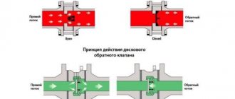
The situation with blocking the operation of the check valve occurs quite rarely. This occurs when debris or foreign objects enter the system. The situation can be corrected by disassembling the pipeline in the problem area and removing the blockage.
How to set the pressure on the relay depends on the operating principle
It all depends on what kind of installation we have in front of us - mechanical or electrical. Since in most cases it is the mechanics that are purchased (it is quite accurate and more affordable), let’s talk about it.
1.5 m3/h For process water
1.5 m3/h For process water
MBFT-75 Membrane for 75GPD
An individual water treatment and water supply installation is most often installed on a private plot of land. It consists of a well, pumping equipment, a pipeline and a hydraulic accumulator with a sensor. The tank collects liquid, which is then consumed. This allows you to achieve an uninterrupted supply of liquid, as well as a stable pressure. In addition, a serviceable relay allows you to reduce the number of times the equipment is turned on, thereby extending its service life.
The operating principle of the equipment is as follows:
- The hydraulic accumulator runs out of fluid, and at the same time the pressure drops below the Rstart parameter, for which a large spring is responsible. Its pressure on the membrane displaces the terminals and closes them.
- The installation is operating, liquid fills the storage tank. As a result, the indicator increases and exceeds the specified parameters - P stop. A small spring acts on the membrane partition and opens the contacts. The fluid supply stops.
- When a resource is consumed (someone opened a tap in the house, turned on household appliances), the release is activated again to maintain a constant amount of H2O in the tank.
This determines how to adjust the pressure switch at the pumping station, that is, what maximum and minimum settings to set. If there were no sensor, then this on and off cycle would have to be done manually.
Features of adjustment “from scratch” and errors during settings
Setting up a pressure switch for a pumping station with your own hands from scratch is much more difficult. This procedure is required when the equipment is assembled in parts and not purchased in a store. In such a situation, several parameters need to be taken into account:
- air pressure in the accumulator;
- relay capabilities - its operating range;
- line length and pump operating parameters.
The lack of air in the tank will cause the membrane to immediately fill with water and gradually stretch until it bursts. The maximum pressure when switching off should be the sum of the water and air pressure in the tank. For example, the relay is set to 3 bar. Of these, 2 bars are water, 1 bar is air.
Connecting equipment
During installation you will have to work with two systems. It is equally important to make the correct connection to both the electrical and plumbing. The installation will not move, so the place can be equipped as a stationary one, having previously provided easy access for repairs/maintenance.
Electrical part
It is best to allocate a separate line; this will extend the life of the device, however, this is not necessary. The copper cable must have a cross-section of no less than 2.5 mm. The sensor itself consumes little electricity, so the voltage value primarily depends on the power of the pump. You will definitely need to ground it, because the electricity + water set is not the safest option. You can follow this scheme when connecting:
When you open the cover on the back of the device, you will see three groups of contacts:
- Ground wires.
- “Line” for phase and zero, coming from the shield.
- The same contacts, but from pumping equipment.
When you have familiarized yourself with the schematic image, perform the standard actions - stripping the conductors, placing their edges in the connector, tightening the fastener. After half an hour or an hour, it is better to try tightening the bolts again, because the copper cable has some ductility.
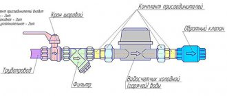
Pipeline connection
This can be done in several ways, but most often a five-pin fitting is used as an adapter. If you don’t have a ready-made device at hand, you can assemble a similar part from classic fittings.
The pipe is attached to the relay body (there is an inlet at the bottom, under the membrane and springs), and the remaining holes are designed to connect the accumulator, hose and main water line. The last outlet can be used for a filter or pressure gauge. With it, setting up a water pressure switch for a pump in a water supply system becomes simple, since it is easier to adjust the sensor not by eye, but by the exact indicators of the device. And it is best to order complex filtration equipment.
Video description
What the pressure should be, see the video:
Optimizing underpressure
The problem of excess pressure also occurs, but quite rarely. Most often it is not enough, and this issue is solved in several ways. Here are the two most popular.
With booster pump
A booster pump is included in the system. That is, this pump is not present to supply water, but to forcibly increase its pressure. This solution can be considered optimal when there is water in the source, but due to its distance from the distribution points, it loses pressure along the way.
Scheme with booster pumps Source ppt-online.org
It is ideal when such a pump is controlled automatically, which itself starts and stops its operation when necessary. This option is suitable for both private houses and apartments, but in the latter case there is a risk of leaving neighbors without water.
Using a storage tank
If there is not enough water in the well (the flow rate of the source is reduced), installing a booster pump will not only not solve the problem, but will also aggravate it. In this case, a sufficiently large storage tank must be installed in front of this pump, and in the absence of water intake, water will be pumped into it.
In this case, the owner himself will decide what pressure is in the accumulator, because this is not important. If such a tank is equipped with a float sensor, it will itself give the pump a command to turn on when the water in the tank is used up to a certain limit.
System with large storage capacity Source seid-nn.ru
If you place the container in the attic, it will also be filled by means of a pump, but it will flow to the flow points by gravity. True, the pressure will not be strong enough, and most likely, you will have to install another pump that will supply water from the tank. By using the second pump, you can place the barrel anywhere – even in the basement.
When automation needs to be reconfigured
Sometimes equipment breakdowns or errors occur. Here are the most common:
- the liquid flow is not powerful enough due to the large suction depth;
- the pump impeller is worn out;
- seals are cracked or dried out;
- difficulties when supplying liquid to the upper floors of a high-rise building or to a tank that is mounted too high.
SF-mix Clack up to 0.8 m3/h
SF-mix Runxin up to 0.8 m3/h
SF-mix manual up to 0.8 m3/h
In such situations, you will need to change the settings set by the manufacturer.
Preparation for the process
What you need to do first:
- fix problems with all water supplies;
- check the indicators in the expander chamber, everything should be adjusted to the lower limit on the relay;
- if necessary, pump up the air - in this case, excess liquid may spill out, this is normal.
What characteristics should be changed?
You can change two parameters:
- RStart.
- Δ P, that is, the difference between the upper and lower limits.
If you do not change the factory value of ΔP (usually it is equal to 1 atm), then when you move Pstart, at the same time Pstop changes by the same amount. Here is a table with the most common problems and options for how to configure the water pump relay:
| Situation | What are we moving? | How |
| Excessively frequent station startup | Increase Rstop | Compress the spring ΔР |
| Pump on too long | The stopping limit needs to be lowered | We lower ΔР while maintaining the starting point |
| The pressure is too high | Reducing Rpusk | We weaken the large spring, and the lower pressure limit automatically tightens |
| Water flows into the taps in a weak stream | Raise Rstart, leave Rstop in the same place | To do this, compress P, weaken ΔP |
Installation
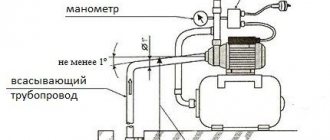
What else should be considered when planning a water pumping station? It is installed near the source. If used year-round, it should have a warm room.
Pipes from a well or borehole are laid in a trench below the freezing depth of the soil. In this case, the source is reliably insulated. A special mesh is installed on the check valve to protect against contamination.
The pumping station is installed on a reliable base, bolted and grounded.
The system is filled with water, after which the pump turns on. After the pressure rises to a predetermined value, it should turn off and turn on again as water is consumed.
Adjustment instructions
One of the most classic devices is the RDM-5 modification. From the factory it comes with settings of 1.4 atm and 2.8 atm. This is usually enough to install a house, but if you plan to install a jacuzzi, then the pressure should be higher.
There are two springs. The large one is for adjusting the upper and lower limits, and the small one is for changing the delta. You can change these parameters by tightening the nuts at the base (the pressure increases), or by unscrewing it - it becomes lower. If you do this with your hands and without measuring instruments, then usually one full revolution is equal to about 0.7 atm.
How to determine relay response thresholds
Usually they correspond to those stated in the instructions. But if the factory settings have been corrected or high accuracy is important to you, then testing can be done. To do this, remove the top cover, there will be a nipple there. You can connect a measuring device to it - a pressure gauge.
Hydraulic tank functions
In the process of organizing an autonomous supply of water from shallow wells in private homes, a pumping station is most often used to lift it to the surface. It is a unit assembled from a self-priming pump, a storage tank and instruments through which the station is put into operation and pressure is controlled.
- However, the station can only be installed superficially and can extract water from a maximum depth of 8 meters (we do not take ejector units into account). In deep water intakes, a submersible pump is used, and the hydraulic accumulator for it must be selected individually.
- There may be more than one such container in the system if, for example, higher pressure needs to be ensured on the upper floor. There are situations when the station simply cannot become a replacement for a hydraulic storage tank, especially since not only cold water supply is organized in the house, but also hot water.
A diagram in which, in addition to the pumping station, there are two more hydraulic tanks Source kadetbrand.ru
- The pressure in a hydraulic accumulator integrated into a particular system will not be the same, just as the containers themselves should be different. They may be similar in appearance, have the same volume or shape, and sometimes even color (it all depends on the manufacturer), but if you place the device on a network not intended for it, this will quickly make itself felt.
Only a tank for cold water is called a hydraulic accumulator; in a hot water system it is already an expansion tank. You can still put it on heating, but not on cold water. What's the difference?
Distinctive features
Inside any hydraulic tank there is a rubber bulb (membrane). So, in tanks for cold water supply systems, the water is inside this bulb, and the air pumped inside occupies the space between it and the walls of the tank itself, as shown in the photo:
Pressure in the hydraulic accumulator of the pumping station and its internal structure Source nasosovnet.ru
- In an expansion tank, the opposite is true: air is pumped into a rubber balloon, and water is around it, in contact with the metal body. Since it is intended for hot water, the permissible pressure and temperature range will be approximately the following: 10 bar/+70 degrees.
- A tank with such indicators is universal; it can also be used with cold water. If the container is intended only for cold water, the permissible pressure will be significantly lower. You can navigate the characteristics by looking at the information label pasted by the manufacturer on the container body.
The permissible air pressure is indicated on the information plate Source sima-land.ru
- And one more important question that requires clarification to understand the topic. The tank body has a certain capacity, which is specified by the manufacturer. Many people mistakenly believe that this is the amount of water that is placed inside. However, this is not so, because part of the container, and a large part, is occupied by air. The tank can only be filled to a third with water (for a body volume of 100 liters, about 30 liters of water).
Note! More water can fit into the tank only when the pressure in the accumulator - 50 liters, or any other volume - is zero. That is, there is no air in it - and, accordingly, the device is inoperative.
On what basis is pressure set?
So, we have already understood that hydraulic tanks differ only in their purpose - for a cold network or a hot one. The volume of the housing does not matter during the settings, so the pressure in a 24-liter accumulator will be the same as in the case of a hundred-liter tank.
- More volume (the shape of the body does not matter at all) means more air. Accordingly, more water will fit. The manufacturer still maintains the balance, and the pressure in the air cavity will be the same in any container (standard is 1.5 bar).
Volume and shape do not matter Source pumpekhoob.com
- When the pump is off, the operating pressure in the network should be twice as high as when it is on. However, under no circumstances should it exceed the limit stated for this device by the manufacturer.
- If necessary, the factory settings can be changed - exactly how depends on the structure of the system. If this is a pipeline that supplies water from a well to the house, the accumulator is usually configured in accordance with the factory parameters of the pressure sensor installed on it.
A well pump connected to a hydraulic accumulator Source de.decorexpro.com
- Most often the range varies between 1.4 and 2.8 bar. The pressure in a 100 liter cold water accumulator (or any other tank by volume) is adjusted 0.2 bar lower (both indicators). This makes it possible to avoid unnecessary pressure surges when turning on taps or plumbing fixtures that use water.
- If another tank is installed in the system - for hot water, then its settings are no longer oriented towards its relay, but towards the cold water accumulator, with a decrease of the same 0.2 bar.
- Maintaining such a gap is an important point, because with higher pressure in the hot pipeline, the float on the automatic air vent will constantly shift and let air in, which should not be allowed.
Advice! To obtain precisely specified pressure parameters, the air already in the tank should be completely vented, and only then pumped up to the required limit.
Pressure sensor with pressure gauge on the hydraulic tank Source rmnt.mirtesen.ru
See also: Catalog of house projects with a boiler room
In a system in which a hydraulic accumulator is present, a drop in pressure usually indicates either a loss of air through the inlet valve or a breakthrough of the rubber membrane. At the same time, when water begins to be consumed, the relay begins to make constant clicks, and the pump constantly turns on.
On a note! In a hot water supply, when the pressure drops, the emergency valve begins to leak.
Having discovered such problems, it is necessary to find out what pressure should be in the pumping station in the accumulator and compare it with the actual one. Perhaps you just need to pump up the air. If this does not help, you will have to disassemble the housing and check the integrity of the membrane.
Settings
Sequencing:
- Connect the pressure gauge.
- Turn on the system and note on the device at what values it turns on and off.
- Tighten the nuts on the springs.
- Perform a test run again.
AMETHYST - 02 M up to 2 cubic meters/day.
Aeration unit AS-1054 VO-90
Main table dispenser AquaPro 919H/RO (hot and cold water)
This cycle can be performed several times until the most accurate results are obtained.
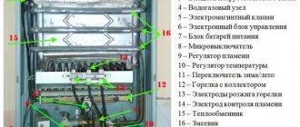
How to configure the block correctly?
To adjust the block you will need:
- a flat-head screwdriver for unscrewing the cover,
- open-end wrench or 8 mm socket.
Before starting work, you need to check the existing start and stop pressure of the pump using a pressure gauge installed together in the block.
If the pressure gauge is not working properly or is missing, you should connect a control pressure gauge to the water supply, with a measurement range from 0 to 6 atm, in increments of 0.1 or 0.2.
First, the plastic cover of the control unit is unscrewed .
Under it, on the block platform, there will be two springs: a large one and a small one. A large spring regulates the pressure at which the contacts close and the pump starts. Often, next to the spring, the letter P is stamped on the metal . Using a smaller spiral, the difference in pressure between starting and stopping the pump is adjusted. May have a ΔР symbol next to it.
How to reconfigure a block:
- Identify the actual moments of starting and stopping the pump using a pressure gauge.
- Decide what new torques should be set, determine whether the difference ΔP between the starting and stopping torques needs to be maintained.
- If the starting moment does not change, then reconfigure the small spiral ΔP. If the start pressure needs to be changed, then the resetting begins with the large spring P, and then proceeds to adjusting the small spring.
- To increase the force of water, the nut rotates in the direction of the arrow on the clock, the spiral contracts. To lower, turn the nut counterclockwise, the spiral will loosen.
- After 1 - 2 turns of the nut, you should start the pump to find out the new moments when the unit starts and stops.
- When the required starting torque is obtained, the pump proceeds to changing the cut-off torque by rotating the small spiral nut. Clockwise rotation, compressing the spiral, leads to a larger range of ΔР, counterclockwise, weakening the spiral, leads to a smaller range of ΔР.
- After 1 - 2 full turns of the nut, a test run of the pump is made again to determine new torques.
- When setting the required moments, you should also make sure that the pump turns off within 5 seconds when the upper cut-off torque is reached, with all valves closed.
How to regulate in a private house?
Adjusting the unit installed in an apartment is no different from the settings in a private house . But in a private house, the start-up and shutdown times are often set higher than in an apartment.
This may be due to the presence of a second floor, equipment on a personal plot that requires higher pressure.
Accumulator pressure
It is formed due to the fact that the liquid presses on the membrane. Because of this, the air in the second part of the tank is compressed and puts more pressure on the body. To adjust this indicator, gas can be deflated or inflated through a regular nipple in the design, like in a car tire. Before connecting the relay, be sure to check and adjust the necessary indicators in the hydraulic tank. It should be equal to 1.5 bar.
Consequences of not making the necessary adjustments
If the pump operates within the range of modes recommended by the instructions, then there will be no serious consequences for it . Users may only experience some inconvenience due to too high or low pressure.
If the station operates outside the established recommendations, for example, does not turn off for a long time or is turned on very often, in this case the station experiences increased loads, which will lead to premature wear of the impeller and the electrical part of the installation. The pump will not last long and will break prematurely.
Choosing the right connection diagram
The installation will definitely contain the elements shown in the picture. The connection will be made in this order:
- Water intake point (city pipeline or individual well).
- Filter.
- Hydraulic accumulator.
- Sensor.
- Additional filtration system.
- Faucet or other sources.
Manufacturer's choice
Above we have presented a specific list of models. Based on them, you can make a choice. Important criteria will be:
- Country of Origin;
- price;
- maximum and minimum limits.
Should we consider electronic analogues?
This is a more expensive alternative that is more accurate. This will be relevant in cases where the water supply network includes expensive equipment, plumbing equipment, as well as at production facilities.
conclusions
We have explained in detail what the structure of a hydraulic accumulator is, and why using it without a qualifier is a bad idea. They also gave detailed instructions for installing the equipment. You can make it yourself at home. To adjust the indicators you will not need any special knowledge or special items. After you unscrew the cover of the device with a screwdriver, everything else can be done manually. We hope that our article was useful and now you know how to correctly adjust the water pressure relay (sensor) for the water pump at the pumping station and in the home water supply system.
Features of the pumping station design
A ready-made pumping station, equipped by the manufacturer, is a mechanism for forced water supply. Its operation scheme is extremely simple.
The pump pumps water into an elastic container located inside a hydraulic accumulator, also called a hydraulic tank. When filled with water, it stretches and puts pressure on the part of the hydraulic tank that is filled with air or gas. The pressure, reaching a certain level, causes the pump to turn off.
During water intake, the pressure in the system drops, and at a certain moment, when the values set by the owner are reached, the pump starts working again. A relay is responsible for turning the device off and on; the pressure level is controlled using a pressure gauge.
Malfunctions in the operation of a household pumping station can cause breakdowns of plumbing equipment
Our recommended article will introduce you in more detail to the principle of operation, types and proven installation diagrams for a pumping station.