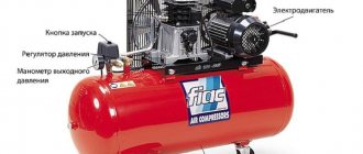
A compressor is a technically complex device, the parts and components of which wear out and fail over time. In most cases, only specialists from service centers equipped with modern diagnostic equipment and tools can solve the problem.
Our technicians will not only fix the current problem, but also identify hidden defects. Thanks to the availability of a large assortment of spare parts in specialized workshops, the repair will be completed in a short time. Let's look at the most common causes of failure of an air piston compressor.
Device Features
Check valves are used in many applications. Such devices most often work in tandem with some kind of tanks or compressors. The main task of a check valve is to prevent loss of pressure built into the system and limit the access of unwanted elements into the system.
In the absence of such a mechanism, the efficiency of the equipment decreases noticeably. For example, compressors are forced to work almost non-stop, which affects not only the operational life of the equipment, but also electricity bills.
Areas of application for check valves:
In addition to maintaining system pressure, check valves prevent liquid media from entering the compressor. With large volumes of distillation, as well as a serious load on the equipment, it is very important to maintain the tightness of the equipment. This point is also critical when working with gaseous compositions, especially hot ones.
In air conditioning and similar equipment, such valves perform two important functions:
Check valves are often used in ventilation technology, both in domestic and industrial areas. Equipment of this type can be seen in apartments - kitchens and bathrooms, in offices, catering establishments, as well as on construction sites and other technical facilities.
The check valve performs the following functions:
In a similar way, check valves are used in plumbing and other systems where it is necessary to shut off unwanted elements.
Unjustified overheating of the unit
The operation of automatic thermal protection is understandable in cases where the temperature in the room is high, there is a low mains voltage (we check with a multimeter) or the installation has been operating without interruption for a long time.
If everything is in order with the room temperature, voltage and operating mode, it means that the filter installed at the atmospheric air inlet is clogged. The filter must be cleaned, rinsed, dried and reinstalled. Such manipulations must be performed regularly, and with constant work - daily. This reduces the load on the compressor motor and reduces overall system wear.
Types of equipment
On the market you can find devices of various form factors, as well as purposes. Equipment is usually distinguished by design features, as well as by installation method. The choice of a particular device directly depends on the tasks assigned to it.
Design types of check valves:
The performance of the device is also affected by the material of manufacture. Check valves made of metal alloys are used in industrial structures where heavy loads are expected. Whereas plastic mechanisms can be seen in ordinary kitchens and bathrooms.
Regardless of the design, check valves can be:
The former can often be found in ventilation equipment. Ball valves are used in compressors, and other types are used in gas and plumbing lines. There are also advanced mechanisms with electromagnetic locking.
The cost of the latter, naturally, is noticeably higher. In this case, the blocking occurs not by means of a conventional spring spring, but by means of an electromagnet. But such valves are picky about distillation products and volumes, so manufacturers of industrial equipment most often give preference to more durable and reliable spring analogues.
What to do if there is a problem?
If your refrigerator breaks down, it is not always worth doing the repairs yourself. This should be done if you have certain skills and special tools.
You can repair the following faults on your own:
- Replacing the door seal. The type of part is indicated in the technical documentation. Repairs can be performed according to the instructions.
- Installation of temperature sensor and thermostat. The mechanism must first be ringed using a multimeter. Spare parts must be selected taking into account the specific model.
- Replacement of the compressor is carried out with experience and knowledge of the equipment.
- Refilling with refrigerant is carried out using special equipment.
If there are problems with the control system or thermostat, you should call a specialist.
Check valve on compressor
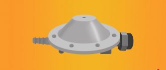
This part is installed between the piston compressor cylinder and the receiver, and prevents air from returning from the storage tank back to the compression chamber after the unit is stopped.
Important! In addition, the return valve, by holding air in the receiver, allows for a smooth start-up of the equipment. If this part is removed, air will press on the piston and the engine will not be able to crank the crankshaft when starting.
In addition to the reverse, a safety valve must be installed on the compressor. This bypass valve is designed for emergency pressure relief if the pressure switch does not turn off the unit engine. The following photo shows the unloading valve, without which, for safety reasons, the compressor cannot be turned on.
Typical faults
The most common problems with an air compressor are:
- the compressor does not start;
- upon startup, thermal protection is triggered or the power supply fuse is knocked out;
- the compressor does not pump, but still hums;
- extraneous sounds are heard;
- excessive heating of the device;
- strong vibration;
- the forced air is characterized by high humidity;
- decreased productivity.
Compressor (engine) does not start
The most common problem that can arise is the compressor does not start.
Insufficient pressure in the receiver or violation of the established settings
The following reasons can be identified that interfere with the normal operation of the engine:
- lack of pressure sufficient to operate the device, poor contact or loose connections. First of all, we check the wire and plug for breaks, and use a special screwdriver-voltmeter to check the voltage in the socket. If the starting capacitors are operational and the voltage is standard 220V, it is necessary to check the fuses and, if they burn out, replace them with new ones;
- insufficient pressure in the receiver or violation of the established settings. In this case, to check, all the air is released from the cylinder, after which the device is tried to start again. If the compressor is working, then the relay should be reconfigured; if not, replace the faulty element;
- Overheating of the piston group is also a common reason why the device does not turn on. The device should be left alone for 15-20 minutes, after which you can try again;
- incorrect startup of the electrical appliance - you must carefully study the operating instructions;
- malfunctions of the piston group - occur due to overload or insufficient oil level.
All these breakdowns can be easily fixed, so there is no need to panic ahead of time. But if there is a characteristic smell, you can suspect the worst thing - combustion of the compressor motor.
When starting, the thermal protection is triggered or the power supply fuse is knocked out.
Causes of failure and solutions:
- The fuse capacity is lower than recommended. To avoid tripping in the future, the fuse must be replaced with a more suitable one;
- network overload – some unused devices should be disconnected;
- Problems with the relay or bypass valve. Requires professional maintenance;
- overheating caused by high room temperatures. It is recommended to move the unit to a cooler, well-ventilated area where the compressor will start without problems.
The engine hums, but does not pump air
A common reason for this phenomenon is low mains voltage. But, if everything is fine with this, then it is most likely that excessive pressure has formed in the receiver, exerting significant resistance to the piston in the process of pushing air. In such a situation, the device turns off for 15-20 seconds, after which the automatic switch is returned to the “AUTO” position.
Design and principle of operation
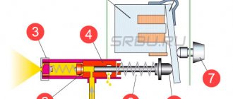
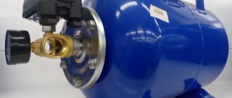
The return design includes the following elements (see figure below):
The return, in addition to the inlet fitting, has a side outlet through which it is connected to the receiver, and 1 thin outlet for connecting a pressure switch.
The check valve works according to the following principle. When the compressor is turned on, air passing through the cylinder suction valve enters the compression chamber, after which it exits through the outlet valve and enters the return inlet fitting (7). When a certain pressure is reached, the valve (6) together with the rubber ring rises and compresses the spring (4). As a result, a passage for air opens. The air moves into the housing cavity (3) and then into the outlet fitting connected to the receiver. After turning off the unit, valve (6), under the influence of a spring and air pressure from the receiver, returns to its place and closes the inlet.
“Weak points” of famous domestic models
Manufacturers of household appliances constantly assure in advertising that their refrigerators are the most reliable and resistant to malfunctions. However, practice shows that each brand has its own characteristic vulnerabilities:
- Atlant. A common cause of incorrect freezing mode is a breakdown of the thermostat. Moreover, the malfunction is often easily corrected by returning the tube to its place. Older models do not tolerate summer heat well, so they require moving to the coolest corner.
- Biryusa. Refrigerators of this brand operate optimally at temperatures from +16˚C to +32˚C. There are often problems with the relay, thermostat, as well as violations of the compressor operating mode.
- Nord. For these models, the starting relay and thermostat often fail, which can be solved by replacing these devices. It is even more profitable that their warranty period is 5 years.
The Belarusian manufacturer's Atlant brand of refrigerators has gained fame as reliable devices with a service life of a decade or more. Currently, 80% of products are varieties of two-chamber models with one and two compressors. There is no technology that lasts forever; breakdowns also happen in the Atlant refrigerator. Let's determine the main causes of malfunctions.
How to make a check valve with your own hands
There are situations when the air compressor return valve has failed, and for some reason it is not possible to buy a new part. In this case, the part can be made by hand.
On the Internet you can find quite complex methods for manufacturing this unit using lathes, milling machines and other equipment. But there is still a way to make a simple homemade valve from improvised materials. A drawing of this unit is shown below.
To make a return you will need a metal pipe or tee, a spring, a coupling, a metal threaded plug and a ball.
The air check valve is manufactured as follows.
After this unit is ready, its inlet pipe is connected to the cylinder of the unit, and the second to the receiver.
Source
Structure of pneumatic relay symbols
The marking of the air pressure switch indicates the entire optional set of the device, design features, including information about the factory settings for the pressure differential.
Let us examine the designations in more detail using the example of devices for air ejectors RDK – (*) (****) – (*)/(*):
- RDK – series of relays for compressors;
- (*) – number of threaded ports: 1 – one port with ¼”NPT internal thread; 4 – four connectors;
- (****) – type of housing design: T10P – version 10 with a “lever” switch; T10K – “button” switch; T18P – execution 18 with a “switch” switch; T19P – 19 s;
- (*) – factory settings of the threshold response: 1 – 4…6 bar; 2 – 6…8 bar; 3 – 8…10 bar;
- (*) – diameter of the unloading valve: the absence of a symbol means a standardized parameter of 6 mm; 6.5 mm – 6.5 mm.
The difference between the minimum and maximum pressure thresholds is set by the manufacturer and, as a rule, has a value of 2 bar.
However, it is also possible to manually adjust the range of two values – maximum and minimum, but only downward.
The specifics of setting up pressure switches for pumping stations are outlined in the following article, the contents of which we recommend that you familiarize yourself with.
Compressor valves - what are they?
An air compressor is a unit whose operating principle is based on compressing and supplying air to pneumatic equipment under the required pressure. Such installations are an indispensable element both in everyday life and in industry, being an autonomously functioning technical unit or being included in more complex electrical appliances (for example, climate control or refrigeration equipment). The schematic diagram of any compressor includes a working chamber and a valve system. And since these devices, like any other mechanisms, can break down, you need to know how they are designed, what types of valves there are, how to choose them correctly or make them yourself. More on all this in the material below.
What could cause the breakdown?
First, let's talk about why the refrigerator constantly works, but does not turn off, in order to solve the source of the problem in the first place. Most often, working without a break is caused by the following reasons:
- You installed the refrigerator incorrectly. For example, they did not take care of the air gap between the wall and the housing, or they placed it in a room with a high temperature, next to a heating radiator, etc. The result can be a hot compressor that won't shut off and performs worse, especially in hot weather.
- The equipment is old and the compressor or thermostat has worn out and should simply be replaced.
- You accidentally set the maximum temperature on the thermostat, as a result of which the compressor automatically maintains the set mode for several hours in a row or around the clock. A similar case is that the super-freezing function is set, which implies uninterrupted cooling operation. It is important to know that the average operating time of the compressor should be 10-20 minutes per start.
Types and principles of operation of valve mechanisms
Currently, the most common types of compressors are screw and piston units. At the same time, screw compressors, for example, those produced by the Belarusian plant REMEZA, are widely used in various industries, and piston compressors are used in everyday life. The latter can be found both in garages of car enthusiasts (compressors such as SO-7B, Forte VFL-50, etc.) and in life support systems for fish in aquariums (Resun compressors, etc.), as well as in household pneumatic tools.
Piston compressors are characterized by a simple design and a relatively small number of parts and components. There are many different designs of such compressor units, equipped with special plate valves that regulate the process of suction and injection of air during operation . Depending on the purpose of compressor units (their performance, power and operating pressure), three types of valve mechanisms can be found:
Inlet and exhaust valves
Inlet and outlet valve assemblies play such a role in the operation of compressor equipment.
Unloader and safety valves
Thus, the compressor pumps air into the receiver cycle by cycle until the specified pressure value is reached. This process is monitored by a special pressure switch (pressostat), which controls the operation of the electric motor by turning it on and off depending on the degree of air compression. As a rule, the pressure switch also includes a starting unloading valve. A pressure switch is connected between the output of the compressor head and the check valve (return valve), which is connected to the receiver and holds the compressed air there.
Important! The safety valve is responsible for relieving air pressure. Its functions include: ensuring a smooth start of the compressor and preventing the return of compressed air to the compression chamber after the engine is turned off.
The necessary pneumatic equipment is connected directly to the receiver, which can be additionally equipped with various devices (separators, filters, pressure equalizers, etc.).
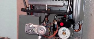
Connection diagram
Pressure switches for compressors can be for different load connection schemes. For a single-phase engine, a 220-volt relay is used, with two groups of connections. If we have three phases, then install a 380-volt device that has three electronic contacts for all three phases. For a three-phase motor, you should not use a relay for a 220-volt compressor, because one phase cannot be switched off from the load.
Flanges
The device may include additional connection flanges. Usually equipped with no more than three flanges, with a hole size of 1/4 inch. Thanks to this, you can connect additional parts to the compressor, for example, a pressure gauge or a safety valve.
Connecting a pressure switch
Relay installation
Let us turn to the issue of connecting and adjusting the relay. How to connect a relay:
- We connect the device to the receiver via the main output.
- If necessary, connect a pressure gauge if there are flanges.
- If necessary, we also connect a relief and safety valve to the flanges.
- Channels that are not used must be closed with plugs.
- Connect the electric motor control circuit to the pressure switch contacts.
- The current consumed by the motor should not be higher than the voltage of the pressure switch contacts. Motors with low power can be installed directly, and with high power, the required magnetic starter is installed.
- Adjust the parameters of the highest and lowest pressure in the system using the adjusting screws.
The compressor relay should be adjusted under pressure, but with the engine power supply turned off.
When replacing or connecting a relay, you should know the exact voltage in the network: 220 or 380 volts
Relay adjustment
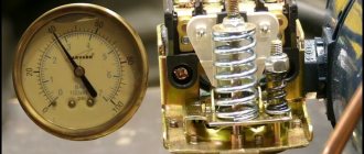
The pressure switch is usually sold already configured and adjusted by the manufacturer, and does not require additional adjustments. But sometimes it becomes necessary to change the factory settings. First you need to know the compressor parameter range. Using a pressure gauge, the pressure at which the relay turns the motor on or off is determined.
After determining the required values, the compressor is disconnected from the network. Then remove the relay cover. Underneath there are two bolts of slightly different sizes. Using the larger bolt, the maximum pressure is adjusted when the engine should be turned off. It is usually denoted by the letter P and an arrow with a plus or minus. To increase the value of this parameter, turn the screw towards “plus”, and to decrease – towards “minus”.
The smaller screw sets the difference between the on and off pressures. Indicated by the symbol “ΔΡ” and an arrow. Usually the difference is set at 1.5-2 bar. The higher this indicator, the less often the relay turns on the engine, but at the same time the pressure drop in the system will increase.
Check valve
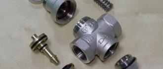
A check valve (return valve) is a device that allows compressed air to flow in only one direction . Structurally, it is assembled (see figure) in a metal case (item 3), inside of which the following are located:
On a note! The check valve has a branch for connecting it to the receiver and a small branch for connecting a pressure switch.
Operating principle
The reverse action valve works as follows. Passing through the outlet valve of the piston cylinder, the compressed air enters the return pipe through the inlet fitting (pos. 7). Having reached a certain pressure, the air lifts the internal shutter (pos. 6) and passes through the cavity in the housing (pos. 3) into the storage tank of the receiver. When the compressor is turned off, the spring (item 4) returns the internal shutter to its place, blocking the path of air from the receiver back into the piston cylinder.
Varieties
On the domestic market you can find compressors with returns made of three different materials: aluminum, plastic and brass. At the same time, the aluminum part differs from its analogues in its high reliability and durability. It is built inside the air duct that connects the piston cylinder to the receiver, and is capable of operating under high temperature conditions (up to 200°C). Whereas a plastic return line is installed in budget models operating at a low temperature of the working environment. As for valves made of brass, they are widely used. Such return valves are quite reliable and perfectly maintain their performance characteristics in cases where the air temperature during compression does not exceed 140°C.
Tips for choosing a part
When choosing a check valve for a compressor, you should know the size of the thread cut at the cylinder outlet . The thread may differ in different unit models. The easiest way is to take the faulty part with you and choose a similar one in the store.
If you need to change the return valve, for example, to a more reliable model, you should familiarize yourself with the technical characteristics of the new part. Some of them are not designed to work with high pressure compressors. Usually, the packaging for the return valve indicates the maximum pressure at which it can operate.
The temperature characteristics of this unit should also be taken into account. If the air, after compression, heats up to high temperatures, then you should not buy a plastic unit. Preference should be given to a metal check valve that is installed inside the duct.
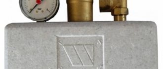
Safety valve
The relief valve (another name is safety) valve serves for emergency release of pressure and is the final device that protects the pneumatic equipment connected to the compressor from damage.
Attention! It is not recommended to operate the compressor without a safety valve.
Experts also include the following types of relief valve:
Despite minor design differences, their operating principle is identical to a safety valve.
Operating principle of the safety valve
Compressor equipment that is not intended for use in industrial environments is equipped with spring-loaded safety valves. When such a compressor operates in normal mode, it is closed (see diagram). In this case, the air pressure on its plate is balanced by a calibrated spring, which prevents the locking mechanism from opening. If the pressure suddenly increases above the set value, the pressing force of the plate against the nozzle decreases and the valve begins to open. This releases excess air, after which the locking mechanism can return to its place.
Important! If the relief valve does not return to its place for a long time, then the compressor must be turned off and the cause that caused the unauthorized increase in pressure must be eliminated
Bypass valve
The bypass (or overflow) valve maintains the pressure of the working medium at a given level. To do this, through the existing branch there is a constant, and not one-time or periodic, as in a safety valve, removal of an excess amount of the working medium (compressed air, gas, liquid), which ensures pressure stability in the system. Such valves are used, for example, in turbochargers installed on automobile internal combustion engines.
Unloading valve
The unloading valve ensures the release of compressed air remaining in the manifold between the piston block and the return line when the compressor stops. In this case, the pressure at the compressor outlet is reduced to atmospheric pressure. In general, the presence of an unloading valve makes it possible to:
In addition, the unloading valve is used in cases where it is not possible to turn off the mechanical drive of the connected pneumatic equipment . Install it at the compressor outlet in front of the return line.
So, the more productive and powerful the compressor equipment, the more complex the valve system. The simplest check valve for use in a household low-pressure compressor can be made by yourself. But for the installation to work correctly, it is recommended to purchase a factory-made part.
Installation Rules
The overpressure relief valve should be installed as close to the compressor as possible. On low-power mobile units, the installation location is provided by the manufacturer. When installing distributed stationary systems, the distance from the compressor outlet to the valve should not exceed 1.5 meters. It is unacceptable to install an emergency release device after the shut-off valve. If the valve is closed for any reason, the valve will not be able to fulfill its protective function, and the increased pressure can seriously damage the equipment or even cause an accident that threatens the life and health of people working nearby.
Before installing or replacing the valve, it is necessary to completely relieve the pressure in the system and turn off the power to the compressor motor. The threaded connection should be wrapped with FUM tape or plumbing thread. First, the threaded connection is tightened by hand, and only after making sure that the thread goes in smoothly can significant physical effort be applied to tighten it with a wrench.
After installing the valve, you need to test it by increasing the pressure in the system to a threshold value. It should work and reset. If this does not happen, the installation cannot be operated until the cause of the failure is identified and eliminated. If the valve is adjustable, you need to use an adjusting hex key to set its operating reset value, using the pressure gauge built into the compressor control unit.
Safety check valve for a compressor: types, design, DIY production
In order to ensure the correct operation of compressor units used almost everywhere today, a number of additional technical devices are used, one of which is a check valve for the compressor. Such a valve, which is equipped with the vast majority of compressor units today, also protects them from premature failure and ensures smooth starting.
Check valve on compressor
Regular activation of automatic thermal protection
This defect is observed when the power supply voltage is too low, poor air flow or elevated room temperature. We measure the voltage in the network using a multimeter; it must be no less than the lower limit of the range recommended . The filter should be replaced or washed according to the unit's maintenance manual.
Interesting! The piston engine is air-cooled and often overheats when placed in a poorly ventilated area. The problem is solved by moving the compressor unit to a room with good ventilation.
Purpose, design features and scope of application
A check valve installed at the outlet of the compressor head allows compressed air to pass in only one direction - to the receiver or any other reservoir. Thus, this valve prevents the return of compressed air located in the receiver or other elements of the pneumatic system back to the compressor. The greatest risk of compressed air returning from the pneumatic system to the inside of the compressor is during breaks in the operation of the device (if the compressor discharge valves do not fit tightly to the seats), as well as at the time of its startup.
Why does pressure drop in the storage tank?
Most likely, the pressure decreases due to an air leak. The reason is in the pressure line itself. Repair of an electric compressor consists of a thorough inspection of the pipeline. To do this, prepare a soap emulsion and coat the joints in the pipeline. If a leak is found, it is treated with sealing tape.
The receiver's outlet valve is capable of letting air through when it is not tightly screwed on or has become unusable.
The piston head of the compressor is equipped with a control valve, which can also cause defective operation of the device. The cylinder head is disassembled, but the air is first released from the accumulator. If such an operation does not help, the valve must be replaced.
Main varieties
Check valve systems, depending on their design, can be:
Direct type check valve for high pressure stations
The material of manufacture may also vary, depending on what environments such a device will come into contact with during operation. In particular, it can be either metal alloys of various types or plastic.
Depending on the type of shut-off element used, check valves can be:
The last three types of devices are used for installation in ventilation systems. Among check valves and safety valves installed on compressors, ball-type devices are the most popular, since they are less critical to contaminants present in the working environment.
Check valves with cone (a), flat (b) and spherical (c) shut-off elements
Among the most modern valve systems, it is worth noting electromagnetic type devices, in which the movement of the valve is controlled not by a spring, but by an electromagnet. Meanwhile, due to the rather high cost and not too much reliability, such devices are not very popular, inferior to cheaper and time-tested spring analogues.
System supercharger does not start
Often the compressor does not start for a variety of reasons. You can avoid this situation by doing the following:
- Operate in accordance with manufacturer's recommendations.
- Perform appropriate maintenance.
- Perform timely replacement of main elements.
- Use only for its intended purpose, reducing the load and providing the required cooling.
There are quite a few different reasons why the supercharger does not turn on. Let's look at the most common ones in more detail.