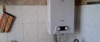
Why did the column stop regulating the temperature?
A common problem with cheap water heaters that have been operating in hard water conditions for some time. After 5-6 years of normal operation, a breakdown occurs: the inability to change the temperature of the water in the column. The reason is the failure of one of the regulators: flow or gas. The automation of Chinese speakers is “treated” by replacing the boiler.
In gas instantaneous water heaters with precise control of water temperature, the cause of the malfunction lies in the fact that the output sensor has burned out. The problem is solved by replacing it. The sensor is relatively inexpensive; with the help of a specialist, it can be quickly dismantled and a new one installed.
In speakers with a temperature controller and electronic control, the inability to set a comfortable mode may be due to software failures. To ensure that the water is not very hot, the software will need to be re-flashed.
gas outlet pipe...
Page 6
- Image
- Text
6
B)
1
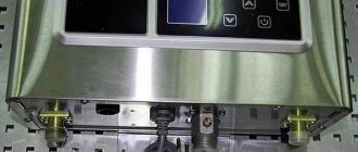
– pipe of the gas exhaust device; 2 – facing; 3 – viewing window;
4
– mounting holes; 5 – cold water supply fitting, G 1/2 thread;
6
– gas supply fitting, thread G 1/2; 7 – hot water outlet fitting, G 1/2 thread;
8
– water temperature display; 9 – button to decrease the set temperature;
10
– button to increase the set temperature; 11 – battery discharge indicator.
Figure 1. Appearance, overall and connecting dimensions of the device:
A) – “NEVALUX-6011”; B) – “NEVALUX-6014”
1
– pipe of the gas exhaust device; 2 – facing; 3 – viewing window; 4 – gas flow valve handle;
5
– cold water supply fitting, G 1/2 thread; 6 – gas supply fitting, thread G 1/2; 7 – hot outlet fitting
water, thread G 1/2; 8 – mounting holes.
Figure 2. Appearance, overall and connecting dimensions of the device
«
NEVALUX-5514
»
Adjusting the gas heater flame
Another way to adjust the water heater is to change the gas supply to the burner. This is done by adjusting the flame. On the body of automatic and semi-automatic hot water boilers there is a gas adjustment knob that reduces and increases the supply of blue fuel. The power of the speaker depends on this lever.
As the flame increases, heating becomes more intense and gas consumption increases. Experts recommend changing the gas supply speed to fine-tune the burner flame. After selecting the burning intensity, for additional adjustments use the knob for changing the water pressure. Another way to change the combustion temperature is to change the winter-summer mode.
To reduce gas costs in semi-automatic models, you can adjust the igniter. The wick adjustment is carried out using a special bolt on the pilot burner. Changes should be made carefully. Reducing the pilot flame too much will cause the water heater to stop working. A strong increase in flame intensity will lead to significant excess gas consumption.
Source
Neva Transit VPG-E
The Neva Transit E column is the basic unit in the manufacturer’s line. This category is represented by three variations, which differ from each other in water consumption and rated power. It is 6, 10 and 12 liters per minute, respectively, for models 6E, 10E and 12E. The power of the units is 12, 21 and 24 kW, respectively.
Transit E is a flow-type unit that is excellent for domestic supply of hot coolant. The model has gained particular popularity among owners of country houses. This is due to the fact that it is capable of operating on main and bottled gas. This makes it a rational purchase for home owners who do not have a central gas supply system.
Gas water heaters Neva Transit modifications E will delight you with the following advantages:
- Reliability;
- Convenient controls.
Low maintenance;
The equipment is perfectly adapted to Russian conditions. It is capable of functioning at a coolant pressure in the system of 0.02 Bar. If your home experiences unstable pressure in the water supply system, the E Series Transit will become a budget unit capable of producing hot coolant when other water heaters would simply stop working.
gas exhaust device...
Page 9
- Image
- Text
9
1
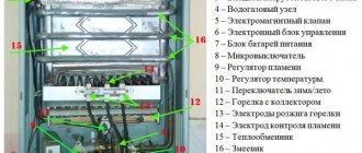
– gas exhaust device; 2 – heat exchanger; 3 – pilot burner; 4 – gas flow valve; 5 – supply fitting
cold water; 6 – gas supply fitting; 7 – hot water outlet fitting; 8 – flame presence sensor; 9 – candle; 10 -
main burner; 11 – electronic control unit; 12 – water-gas unit; 13 – battery compartment;
14
– water drain plug with valve; 15 – water flow tap (located under the lining); 16 – thermal relay (sensor
traction); 17 – frame; 18 – screws for fastening the cladding; 19 – plate; 20 – thermal relay (water overheating sensor); 21 –
microswitch (water flow sensor); 22 – fitting for measuring inlet gas pressure.
Figure 5. View of the device “NEVALUX-5514”
without cladding
Neva Transit VPG-E I
This unit in its basic version is equipped with a power-on indicator, which can be represented by a display on which the parameters of the coolant are indicated.
Among the design specifics it is important to note:
- Built-in automatic heater control;
- Pulse type ignition;
- Built-in temperature sensor;
- Long lasting burner;
- Energy efficient heat exchanger.
This model is equipped with a twenty-minute safety timer. The unit is supplied to the market in two variations, the power of which is 21 and 24 kW.
The Homeowner's Encyclopedia.
We are in social networks
Popular articles
How to become “unpalatable” to mosquitoes and ticks
Growing a melon is easier than a tomato
The whole village is planting peanuts
Fast acting fertilizer
You're watering the garden wrong
Neva Transit VPG-EM
Units in this series are water heating equipment that can automatically maintain the water temperature at a given level, but not higher than 55 degrees. The design provides for smooth gas modulation. The built-in rod makes it possible to reduce the amount of fuel consumed and increase the efficiency of heating the coolant. In addition, the rod extends the life of the column by significantly reducing salt deposits on the heat exchanger. This makes it possible to maintain excellent thermal conductivity characteristics for many years.
gas exhaust device...
Page 8
- Image
- Text
8
1
– gas exhaust device; 2 – heat exchanger; 3 – pilot burner; 4 – water temperature sensor;
5
– cold water supply fitting; 6 – gas supply fitting; 7 – hot water outlet fitting;
8
– flame presence sensor; 9 – candle; 10 – main burner; 11 – electronic control unit; 12 – water-gas unit;
13
– battery compartment; 14 – plug for draining water; 15 – water flow tap (located under the lining);
16
– thermal relay (traction sensor); 17 – fitting for measuring inlet gas pressure; 18 – plate; 19 – frame;
20
– screws for fastening the cladding.
Figure 4. View of the device “NEVALUX-6014” without cladding
Neva Transit EMT
This model is equipped with a forced exhaust gas exhaust system. The device is ideal for use in rooms where there is no smoke exhaust system. The fan effectively removes smoke through the duct. If your house does not have a centralized chimney, the Transit EMT series will be a suitable choice.
Among the design features of this model we note:
- Temperature control indicator;
- Automatic ignition system;
- Combustion flame control system;
- Built-in fuse that trips when the power supply is turned off;
- Fan with built-in blowing function;
- Smoke exhaust pipe made of stainless steel.
Note that the Neva Transit EMT dispenser is capable of operating at low water pressure. This is especially true for some regions of Russia, where water supply problems are normal.
Typical faults
Since gas water heating systems fail from time to time, it would be a good idea to learn the most common breakdowns, their causes and methods of elimination. We will look at the two most typical faults for the Neva Transit gas water heater.
The burner does not light
Almost every owner of the Transit model faces a similar problem. The reason may lie in a malfunction of the spark generation unit. Typically, replacing this unit will fix the problem.
First you need to dismantle the front panel of the unit. Having removed the casing, you will see the block we need, fixed with bolts. The wires should be disconnected from the contacts carefully by pulling them down. They must be inserted back in the same way.
The column lights up every once in a while
Many people attribute this problem to low water pressure. But, as a rule, the reason lies in the need to replace the membrane. The part itself costs around 100 rubles, so repairs will not be burdensome for the family budget.
We present the procedure in the form of an algorithm:
- Disconnect the membrane unit;
- Turn off the electrics;
- Disconnect the pipes;
- Remove the block from the column;
- Open the block by unscrewing the 4 screws;
- Replace the membrane.
conclusions
So, we looked at the features of the units of the Neva Transit model range. From the information presented we can conclude that this technique is a budget engineering solution that everyone can afford.
We looked at typical malfunctions for the Neva Transit gas water heater, and also described methods for solving the two most common problems. The information presented will help you choose the appropriate modification of the Transit series dispenser and understand the features of its operation and repair.
Source
. INDICATION OF SAFETY PRECAUTIONS…………………………….
Page 2
- Image
- Text
2
CONTENT
1 . SAFETY INSTRUCTIONS
………………………………………………………………………………………………… 3
2. DESCRIPTION AND OPERATION OF THE DEVICE
…………………………………………………………………………………………….. 3
2.1. Purpose of the device
……………………………………………………………………………………………………………….. 3
2.2. Specifications
……………………………………………………………………………………………………. 4
2.3. Contents of delivery
…………………………………………………………………………………………………………………… 5
2.4. Device structure
………………………………………………………………………………………………………………… 5
2.5. Operation of the device “NEVALUX-6011” (“NEVALUX-6014”)
…………………………………………………………… 10
2.6. Operation of the device “NEVALUX-5514”
…………………………………………………………………………………………. 12
3. INSTALLING THE DEVICE
…………………………………………………………………………………………………………….. 14
3.1. Installation location and diagram
……………………………………………………………………………………………………….. 14
3.2. Installation of the device
…………………………………………………………………………………………………………………….. 15
3.3. Connecting the device to the water supply network
……………………………………………………………………… 15
3.4. Connecting the device to the gas network
…………………………………………………………………………………… 16
3.5. Connecting the device to a liquefied gas cylinder
………………………………………………………. 16
3.6. Rules for installing flexible hoses
………………………………………………………………………………………. 16
3.7. Connecting the device to the chimney
…..……………………………………………………………… …….18
3.8. Battery Installation
………………………………………………………………………………………………….. 19
3.9. Checking the device
…………………..……………………………………………………………………………20
3.10. Conversion of the device to a different type and pressure of gas
……..…………………………………………20
4 . USING THE DEVICE
…………………………………………………………………………………………………….. 19
4.1. Turning on the device
………………………………………………………………………………………………………………. 19
4.2. Water temperature regulation
…………………………………………………………………………..21
4.3. Turning off the device
……………………………………………………………………………………………………………. 21
4.4. Replacing the battery
………………………………………………………………………………………………………. 21
4.5. Frost protection
……………………………………………………………………………………………….. 21
4.6. Actions in case of emergency
……………………………………………………..22
5 . MAINTENANCE
………………………………………………………………………………………………. 22
5.1. Inspection
……………………………………………………………………………………………………………………………………. 22
5.2. Care
………………………………………………………………………………………………………………………………………… 22
5.3. Maintenance
……………………………………………………………………………………………………. 22
6. POSSIBLE DEVICE MALFUNCTIONS AND METHODS OF THEIR ELIMINATION
……………………………. 24
7. TRANSPORTATION AND STORAGE RULES
………………………………………………………………………. 27
8 . WARRANTY
…………………………………………………………………………………………….. 28
9 . CERTIFICATE OF ACCEPTANCE
…………………………………………………………………………………………………… 29
10.
NOTE ABOUT INSTALLING THE DEVICE AND CONDUCTING MAINTENANCE
….. 29
11.
CATALOG OF DEVICE COMPONENTS
……………………………………………………………………………..30
12. SERVICE CENTERS FOR MAINTENANCE OF NEVALUX WATER HEATERS
……………………36
How to properly adjust the Neva 4510 gas water heater yourself?
A Neva 4510 gas water heater is installed. How can I independently adjust the temperature on this water heater?
It's not hard to do.
As you can see on the front panel of the Neva-4510 gas water heater, there are two handles.
If you stand facing the column, then the right handle is the water flow regulator, and the left is the gas handle.
You can adjust the temperature of the outlet water using either one or the other knob.
If the left knob is set to the “maximum gas supply” mode, then accordingly the column will begin to consume more gas and the water at the outlet will be hot.
The right handle works in the same way; the more you open it, the more powerful the flow; if you do not change the position of the left (gas) handle, the water will be colder.
And then everything is individual, the settings are made based on the water pressure in your system.
There are no general recommendations here, like “put your right handle in such and such a position.”
Look and decide locally, if the water pressure in the system is weak, but the column turns on, then set the right knob to the “maximum flow” mode (the toggle switch is all the way to the left), and gradually turn the left knob from the “minimum flow” towards the maximum, as Only the temperature of the water at the outlet will suit you, leave it that way.
In this model of the column, standard Chinese automatic equipment is installed, with two adjustment knobs - one for water supply (which regulates the temperature), and the second for gas supply and flow (combustion quality).
Adjusting the gas water heater is done with fairly simple movements:
The first is to set the handles (both) to the middle position.
The second is to start the gas water heater.
Third, adjust the combustion of the burners (the fire should burn blue, without slipping or rising from the burner, the flame is even, the burning sound is minimal) - turn the gas supply knob in both directions, don’t be afraid, find the position where the gas will burn as needed.
Fourth - use the water supply knob to adjust the desired temperature at the outlet of the column - by reducing the water supply, you will increase the temperature, and by increasing the supply, you will lower it.
After setting up, check several times by repeated starts to see if the automation works clearly, turning the column on and off.
It happens that you want to save as much as possible on water and gas in order to minimize their consumption, this is done as follows.
With the column running, you need to very smoothly turn its adjustment knob in the direction of decreasing water flow until the column turns off (perhaps it won’t turn off to the extreme position, that’s good!) If it turns off, then you need to slightly return it to the reverse position until the column will not light up again.
Next, use the gas supply knob (towards a decrease, of course) to regulate the combustion and, accordingly, the temperature of the water at the outlet - we check everything is ready, several times, if it does not ignite, you need to add a little water and gas, respectively, until it ignites!
After such adjustment, the geyser will consume a minimum of gas and, accordingly, heat a minimum of water!
Source
Features of choice
Water supply devices can be classified into flow-through and storage. There is no need to turn on the storage model every time you need hot water. The container is well insulated, so it retains heat for a long time. The heat exchangers of such columns are more efficient, but the equipment still has certain disadvantages, which include its impressive weight and the need for additional reinforcement of the ceilings before installation. The concrete base will need to be prepared, which entails additional costs. If you also decide to acquire the equipment described, then you should pay attention to the “Neva-4513” column, which will be discussed below.
Repair of gas water heater Neva Transit
Hi all. I haven’t written something useful for a long time and I hasten to provide you with a small manual on how to correct a malfunction in geysers. Or rather, two malfunctions. I repaired it twice and in this article I will combine both failures.
Several years ago I purchased a Neva-Tranzit gas water heater with forced exhaust. When you open the water tap, the exhaust fan starts and the burner lights up.
I want to warn you right away!
This work should be carried out by a gas worker! But if you have straight hands, do not be lazy to follow a few simple rules before repairing any gas equipment:
Shut off the gas supply to the gas water heater,
If the speaker is powered by an electrical outlet, turn it off
Ventilate the room while working.
Specifications
Gas water heaters are produced in 3 types of power - low, medium, maximum. Water heaters have high efficiency and are able to maintain the temperature of the water.
Gas heaters are equipped with safety sensors, they minimize the possibility of fire. When the burner goes out or the liquid supply stops, the column turns off. Built-in sensors for controlling draft, flame, and temperature ensure simple and safe use of the device. Hanging models are small in size.
Fault No. 1
The gas burner does not light.
And then, at a wonderful moment, the burner began to work poorly, either started every other time or did not work at all. After a little analysis (observed the start when opening the tap), I noticed that the gas could not ignite due to a weak spark. As you can see in the photo below, three contacts approach the burner, two contacts create a spark through the generation unit, the third monitors the flame. If the fire goes out, the third contact tells the sensor that it is necessary to turn off the gas. In my situation, only one contact gave a spark and that one was intermittent.
To eliminate this malfunction, it is enough to replace this spark generation unit.
First, remove the front panel of the speaker. To do this, remove the water adjustment knob (pull it towards you, carefully ????). The front panel is held at the top and bottom with self-tapping screws, unscrew and remove. Just don’t pull, there are wires going to the buttons on the panel, you need to carefully disconnect them from the panel.
The ignition unit is supplied without contacts, but with wires. The block is held on by bolts and connected using a connector. The wires are disconnected from the contacts by simply pulling them down. And they are inserted back with a little effort; there is a needle inside that contacts the wire. Before installation, I recommend checking that the wire has an even cut. There is nothing complicated here.
Let's move on to the second malfunction of the gas water heater.
Principle of operation
In atmospheric water heaters, you first need to light the pilot light directed towards the burner. Then the hot water tap opens, which increases the pressure inside the system. The design of the water unit of the gas column (or “frog”) is such that the flow passing through it affects the internal membrane, which moves the rod directly connected to the gas valve. The valve moves back, thus opening the supply of gas-air mixture to the burner. When interacting with the pilot flame, the mixture ignites and the water begins to warm up inside the coil.
Problem #2
Even with good water pressure, the column does not light up immediately
Yes, and you don’t always have to worry about water pressure either. After four years of almost constant operation, my gas water heater began to have trouble starting. I tried to blame everything on the weak water pressure, but I noticed that even with good pressure the column continued to mope.
I’ll say right away that this malfunction can be eliminated by replacing the membrane in the block, which is shown in the photo below.
And here is the brand new membrane itself. Its cost does not exceed 100 rubles.
Now let's get to the membrane in our column. I’ll say right away that you’ll have to disassemble half (the bottom) of the column, so be patient and everything will work out.
And also, I did this for the first time and therefore there is no catch that anyone with straight arms can do it.
We need to disconnect and remove from the column the entire block where the membrane is located. To do this, as always, mark the connectors with a marker and disconnect all electrical wires.
After the electrics, we move on to the pipes through which water and gas flow. Here two Phillips screwdrivers may come in handy, a short one and a long one. Also stock up on a dry cloth, as some water remains in the pipes. It is necessary to ensure that water does not get on the electrics of the speaker.
It's not entirely convenient to work with, but it's worth it. Our unit must be disconnected from the side of the ignition unit (right) and from above from the tube that passes through the burner.
Next, our block is removed from the speaker body. Next, it will need to be disassembled to replace the membrane. As shown in the photo below, unscrew the four screws.
The angle is from the other side. The photo quality is not very good, but everything is clear. ????
Having unscrewed the screws, we open our block with the membrane, since it comes into contact with water, it may take a little force to separate the two halves. They can get attached to each other. And here is our coarsened membrane.
With a simple movement, it is removed and a new one is put in its place. When assembling, you must ensure that the membrane is in place.
Assembly proceeds as usual in reverse order. Monitor the quality of the connections, do not distort the pipes when connecting. Tighten the screws firmly (within reason).
After assembly, the speaker worked better than new! It took me about an hour to do all the work without rushing (I also took photos).
- Ignition unit within 500 rubles.
- The membrane costs about 100 rubles.
The column works like new. Good luck!
What is a gypsum tongue-and-groove board?
Gypsum tongue-and-groove board is a building material shaped like a scalene parallelepiped. If the working (rough) brick is made from clay (ceramic brick) or sand and lime (sand-lime brick), the base of the PGP slabs is gypsum.
By design, the sides of the tongue-and-groove slab have a tongue and groove for a strong connection of adjacent slabs. The side with the groove is called the supporting side, the side with the tenon is called the docking side. In documentation and construction documents, gypsum tongue-and-groove board is abbreviated as GGP. The plate produced by Knauf is called Knauf-gypsoplate.

