For many people, a country house is something like a cherished dream - the prospect of taking a break from the bustle of the city in a cozy corner seems quite rosy. Moreover, you want not only to purchase a ready-made building with a landscaped garden plot, but to create the estate of your dreams, in which all your wishes regarding design and layout will be correctly embodied. There is only one thing left to do - transfer your ideas to paper, and only then, having drawn up a house project and determined its location on the site, bring it to life (engage in the actual construction of the house). If regarding the second point, by definition, there can be no doubt about the need for third-party help - even if you are a professional builder, you will not be able to build the right mansion yourself, but the costs of hiring an architect can be eliminated. How can design and construction be made cheaper? Yes, it’s very simple - it’s quite possible to do the work yourself, even without any special skills in creating a private house project. Designing a house (drawing it on paper schematically) is actually not that difficult!
What should you consider when designing your own home yourself?
The most important thing is that the house construction project you develop is created based on the following principles:
- Multiple functionality - that is, the house built according to this project will be convenient and practical in all respects. A do-it-yourself house design should be no worse than an architect’s;
- Simplicity of design - it will not be difficult to design a house only if it does not involve any frills. The creation of some particularly complex project, the implementation of which will require a huge amount of creative delights, is highly discouraged for a person who does not have a special education, because some fundamentally important things may not be taken into account;
- Aesthetics - of course, a country house should look beautiful and please the eyes of its owners. The design of a reliable house should also be spectacular!
Remember - if the project is created taking into account these principles, then it will be very good in life. Again, we are talking about a rather primitive independent structure - an amateur would not design a premium-class cottage. Only an architect should be involved in designing houses of this level - beginners here very often make mistakes.
Geological exploration of the house site
Where does “do-it-yourself home project work” begin? First of all, when working on a house project yourself, it is necessary to conduct a geological exploration of the site - assess the nature of the terrain, soil and find out the groundwater level. The best time of year for this is spring, then their level is as high as possible and it is possible to determine this indicator with maximum reliability. It is very important to do this based on the fact that this indicator is of greatest importance when laying the foundation of a private house.
To determine the depth of groundwater, we recommend contacting a specialist
Nuances of independent design
As with any complex issue that requires an individual approach, with design, everyone must figure it out on their own, by trial and error. This is a long process and there is no universal “recipe”, but there are a number of recommendations that can make it easier.
- When working on the design of the foundation, you can use not only online calculators to simplify calculations, but also an “extract” of other people’s experience. Almost all types and options have already been designed by someone; a specialized theme will help you avoid major mistakes and costly alterations. But in order to choose the appropriate type of foundation, even for a private house, you cannot do without data on the type of soil and groundwater level. Is it worth doing geology or is there an alternative - in this material.
- For small houses, it is not a problem to lay communications even through the entire perimeter, but if we are talking about a square area under and over a hundred meters, it is better to place wet rooms (bathroom, kitchen) nearby. And if there is an attic or second floor, then on top of each other.
- In a comfortable home there are always utility rooms, if space is limited, at least hidden storage systems.
- Engineering systems cannot be left “for later”; depending on the chosen type of foundation, the optimal zones for mortgages must be calculated or the water supply and sewerage distribution must be fully worked out.
- In order not to flood the street or not make one and a half meter walls, when choosing materials and technology, you need to take into account not only the budget and complexity of the work, but also the standards for the thermal resistance of enclosing structures for the region of construction. It is advisable to spend extra time and replay everything several times when creating a model in order to be sure to stay within the budget and not go broke on energy bills.
Start designing a house
For a clear example, our editors used the free demo version of the Visicon program. But all the steps can be performed on a regular sheet of paper. For example, a simple project of a two-story house 10 m x 10 m was chosen
To design houses, you will need to “arm yourself” with an ordinary checkered notebook sheet and a pencil, while setting the appropriate scale. The most rational thing to do in this situation would be to do the following: ten meters of land should be designated by two squares. Thus, one centimeter on a ruler will equal 1 meter in real life - the ratio is one to one hundred.
Step 1: draw the outline of the house on a notebook sheet using a ruler and pencil on a scale of 1:100, i.e. 1 cm on paper is equal to 1 meter
Drawing on paper the outline of the site itself, as well as future buildings. In this case, all work must be carried out in strict accordance with the correct scale - by carefully measuring every meter on the ground and putting it on paper in accordance with dimensions one to a thousand, you ensure the reliability and aesthetics of the building being constructed. You can draw a project this way very quickly. It is imperative to take into account not only the contours of the site allocated for design and construction, but also all the objects located on the site that were there even before its planned construction, and at the same time there is no possibility of moving them. After this, it will be possible to begin designing the building itself - to simplify the task, we will assume that the designed house will consist of four rooms, a kitchen and two bathrooms (standard housing for a family of several people).
Programs for creating drawings
We will recommend and introduce the most popular and frequently used programs for creating drawings.
Paid programs
Let's start with the highest quality and multifunctional, but paid offers.
KOMPAS-3D
The most popular program in Russia, often used by both students and engineers.
There are many advantages and disadvantages, the main and most important ones are:
- a simple and accessible interface that will be understandable to any user;
- 3D design with the ability to transfer to 2D and back;
- export and import from third-party CAD applications;
- function to rotate and scale an object;
- saving the final file in several formats at once: from DWG to IGES.
In addition, KOMPAS-3D offers additional modules for working with electrical circuits, pipelines, springs, etc.
AutoCAD
If you are dealing with drawings of circuits, furniture or houses, this option will be one of the best.
It is somewhat more difficult to use compared to KOMPAS-3D, but has a lot of features and tools, including:
- 3D design of assembly drawings and parts;
- quick correction of errors within the framework of a ready-made drawing;
- parametric modeling, which simplifies and speeds up the process;
- automatic construction of geometric shapes.
The only disadvantage of the two programs already mentioned is the lack of a free version and the ability to freely use the program for more than a month (as part of a temporary subscription).
Free programs
Let's move on to simpler and less functional, but free and accessible options.
A9CAD
In many ways similar to AutoCAD. And if you liked working with it, but there is no way to extend your use, turn to the free A9CAD.
A familiar interface and features, ease of use and simply an excellent option for beginners who will forgive the program for the lack of many functions.
If creating 2D drawings is enough for you, feel free to install it. Among the most useful abilities, we highlight the construction of drawings of varying complexity, indication of dimensions, preview and support for layers.
NanoCAD
The second best and most accessible program in which you can create entry-level and intermediate-level drawings.
Despite its simplicity, NanoCAD supports 3D modeling and vector graphics. And if you purchase the paid version, there will be even more possibilities. But the free one is completely independent and justifies itself.
Other advantages: minimum requirements for installation, construction of electrical circuits and full compliance and support of CAD - the official and recognized standard.
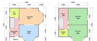
First floor project
We draw the vestibule and the hallway on the sketch - and from there there will be transitions to the kitchen and other rooms. The location of the premises must take into account the following points:
- The bathroom and kitchen should be placed in close proximity to each other - thanks to this location it will be much easier to carry out communications;
- It’s very good if the drawn up project implies the absence of passage rooms - this is an integral element of comfort;
- On the ground floor, it is necessary to take into account the presence of all auxiliary structures and premises - their location will be very important not only to ensure the functional suitability of the house, but also for the comfortable movement of residents.
Step 2: draw all the rooms and premises of the first floor with the required size
After this, we arrange and plan all the doors of our house
Step 3: designing doors on the first floor
Then windows, taking into account the desired lighting of the rooms and your budget
Step 4: designing windows on the first floor
As a result, we get this first floor:
This is how the 3D model of the first floor turned out
Detailed description of the parts of the finished house project
The finished project is conditionally divided into groups of working drawings, namely:
The first set of working drawings in the finished project is the Master Plan (GP). This is a set of six drawings:
- Situation plan, scale M 1:2000. On the plan we see the designed object, taken from outer space in the wind rose (photo 0003).
- Basic plan, scale M 1:500. The plan is also on a smaller scale (photo 0004).
- General plan, scale M 1:500. The plan shows a site plan with a house plan and explanations of areas and premises (photo 0005)
- Landscaping plan, scale M 1:250. On the plan, the same on a better scale.
Drawing the second floor
Here everything will be much easier - after all, the rooms in the house can be located identically (the most important thing is not to change the relative position of the bathrooms - in order not to complicate communications). It will be enough to design the location of the front door (many architects recommend making two entrances to the second floor - at home and from the street) and windows.
Step 5: We plan the premises of the second floor in the same way. Don’t forget about communications - we place the bathrooms and bathrooms one below the other
Step 6: Place the Doors
Step 7: draw the second floor windows
We received this 3D model of the second floor
Basement
There is no such thing as excess territory. Everything that is below ground level has its own specifics. You can always find a use for this. There will be a perfect space for storing preserves for the winter, a bathhouse or sauna, a workshop, a sports room, a laundry room, a boiler room, etc. With a sloping landscape, a garage is very conveniently located under the first floor.
Decide how you will get there. There are options for going down in the common block from the stairs to the second floor or a separate entrance from the street, technical space. You must understand that the area occupied by the passage will also be inaccessible for placing some objects on the 1st floor.
Once you have decided, draw a large-scale plan highlighting all the thicknesses of the partitions, locations of window and door openings, and stairs. A convenient option is to place all communications at this level. The design of the design must be taken into account. As a result, you will receive a diagram on the basis of which you can continue further creativity.
Attic and roof design
We decided to create a house project ourselves - there would be no need to try to draw some kind of too “abstruse” roof with a lot of bends. Remember - the roof is one of the most important structural components in the house, and trying to create additional aesthetics by questioning its reliability is certainly not worth it. All this will lead to leaks occurring at the bends. If you are drawing a project, please adhere to the principles of minimalism in architecture.
To design such a roof, you cannot do without an architect.
Dependency of designing a house with insulation
There is one very important rule - all auxiliary premises must be built on the north side. Despite the fact that thermal insulation performed using building materials is of paramount importance, the relative position of the rooms should also not be overlooked - if only because of the savings in energy consumption for heating the house.
How to make a house plan correctly
Solving such a problem is a creative and interesting undertaking. All family members will be happy to take part in it.
Initially, decide on the volume of the building, the presence of a basement, garage, second floor or attic. Match your wishes with your financial capabilities. Decide on your individual preferences.
Decide what material the walls, foundation, and ceilings will be built from. The thickness that must be transferred to the plan in the future depends on this. Find out the possibilities of connecting communications and creating a sewer system, and a place for a well. Armed with all this knowledge, proceed directly to creating the diagram.
Approval of the project to begin construction
The need to adjust the project. Even if you yourself were able to depict the house of your dreams on paper, you will still need to consult with specialists before starting construction of the house - the opinion of a competent foreman or architect will not be superfluous. At a minimum, the following points will need to be agreed upon:
- Carrying out electrical work;
- Conducting your own sewerage system;
- Carrying out water supply;
It is necessary to understand that all the above issues are not an artistic or architectural part of the project. These are all the most routine issues, a competent approach to solving which is provided only by professionals in their field. As a last resort, any oversight in independently drawing up a house project, which was made by a person who does not have a specialized education, can be corrected by a competent foreman who understands the practical side of any idea much better. Although even if the project is drawn up by professional architects, purely practical shortcomings cannot be ruled out.
Independent work on a house project and its advantages
You can create the design of your house yourself - in order to develop drawings of the relative position of certain rooms, as well as determine the place of the house on the site, you do not need special knowledge. A competent and responsible approach to business will ensure the success of your event. However, in terms of communications, it will be necessary to consult with professionals. This way you can properly plan a house that will serve you faithfully.
Read about the following stages of construction:
Types of foundations used in construction
Which is better to choose a foundation for the soil and type of house
Water supply for a private home
Watch also the video on how to make a house project yourself
Read about the previous stages of construction:
Layout of land for building a house
How to learn to read drawings?
Drawings are 2-dimensional architectural schematic sketches that show the size of a building's design. For materials that will be used in construction. Learning to read blueprints is important for builders and anyone who hires architects to draw them.
Spatial imagination training
Standard drawings usually have three projections of an object in which the coordinate points X, Y, Z are located on the axis. However, with their composition, the scaling remains and the same is set for all.
It is human nature to observe each object or detail in geometric isometry from a certain angle of view. This often happens in the branches of mechanical engineering drawing, and in the design development of objects of artistic and technical design. Therefore, it is worth presenting the drawing object as flat in a certain projection.
And an additional detail is the projection connection of different images of the drawing object. If all the elements of both configurations are built incorrectly with scale distortions, which will lead to a discrepancy between the copy of the drawing and the originals. Therefore, it is worth following a number of rules in the process of drawing up a projection:
Measurements are carried out using a ruler - for simple ones, with a caliper or micrometer - for complex parts, for all dimensional elements. Establish their relative position for each of the projections of the part. Compare the results obtained with a real image of the part. With bug fixes. Final distance measurements are taken on the original object or its mock-up drawing. If all the data is correct and matches, then the diagrams and drawings were read correctly.
How to apply dimensions correctly?
It doesn’t matter what scale the drawings are made, all attention is paid to the base of the part and its dimensions. When writing a certain number, the unit of measurement, which is standard, is not shown. To indicate the parameters of the part, a dimensional path is drawn with a number located on it. It is drawn parallel to the part segment and is limited by arrows. The minimum distance between the dimension line and the contour of the part is 10 mm.
How can I get help acquiring independent technical graphics skills? To master the skills of reading drawing tables, it is necessary to conduct a training course and practical work. Carry out repairs of simple designs of household appliances to produce new and old parts. In this case, it is also necessary to make primitive drawings.
Learn how to read drawings correctly, and then learn how to represent a flat picture on a drawing in 3D form. The skills of reading drawings help to competently produce all kinds of objects, assemble them from components, the final product, obtain the entire apparatus, models and much more.
Types of formats
The format of the sheet with the drawing is determined by the length of the line drawn on the edge of the sheet. The internal ones are made with distances of 2 cm from the left side and 5 mm from the others. It is worth adhering to the exact calculations of the drawing so that when reading them there is no disagreement about what the part looks like.
Drawing frame formats are divided into main and additional directions. The first type included all the resulting schemes by halving the lines from point A0. The dimensions for drawing A1 are carried out so that when the largest axis is divided into two, a rectangle similar to the original sample is obtained. The designation of standard formats consists of a letter and a number from one to five.
Automatic drawing creation
The first place was taken by those drawings made using computer-aided design programs. For different designs and parts. This applies to two systems - Auto-cad and Compass. They involve reading drawings of a different type. And the image of the entire node is set. And then the parts included in the assembly unit are designed. Thanks to their work with entire libraries of source data. After all, they include profile normalized and standardized elements. Using it in work, the developer is able to insert a fragment into a workpiece, controlling individual parameters, and adapt the drawing to new source data.
Video description
The video will tell you more about determining the required area of the house and its layout:
See also: Catalog of companies that specialize in the construction of frame houses
We get a box of 12x15 meters. In the case of a small area, you can think about reducing the parameters by using a second floor or attic. We transfer these dimensions to scale onto graph paper, a sheet of squared paper, or into a computer program. The last option is the most convenient, as it allows you not only to make changes, but also to view the project in a three-dimensional image. And also immediately think about the placement of equipment, furniture and household appliances.
Screenshot from the Sweet Home 3D program page Source i.ibb.co