Drilling a well is the optimal way to provide water to a suburban area in the absence of a central water supply line due to the low cost of the work compared to well water supply and technological accessibility. These factors allow owners of individual plots to carry out drilling independently after they have made a simple and inexpensive drill for a well with their own hands.
There are various designs of drilling devices for individual drilling; their choice depends on the composition of the soil on the site, the depth of the water layer, and the pumping equipment used for water intake in the future.
Well types
Studying the technology of individual drilling and methods of making drills with your own hands in the case of carrying out drilling work independently without the involvement of third-party specialists or commercial organizations will help save homeowners not only financial resources, but also earn money, if desired, by providing such services to local residents.
Four well drilling technologies
Several types of wells are used to collect water in the areas; when drilling independently, the maximum deepening threshold does not exceed 35 m, so they drill shallow Abyssinian and sand wells with their own hands. In this case, the drilling device performs two tasks: it forms a shaft in the ground, into which the casing is then lowered, and removes the soil, softened after drilling, out. Almost all methods additionally use water, which facilitates the passage and extraction of rock accumulated in the mine to the top.
Manual drilling with electromechanical devices
For independent drilling, various technologies and several types of drills are used, the main of which are:
Screw (spiral) . Auger drilling is the main type of well creation using the industrial method; installations for its implementation occupy a leading position in terms of prevalence and are used by organizations professionally involved in drilling technologies. During excavation, the drill is lowered to a considerable depth by extending it with rods, and excess soil is extracted out hydraulically using water.
A factory-made manual auger drill for a water well can be bought in a retail chain; to implement the screw method at home, a drill is made with your own hands using welding. With the dry method, they travel a distance of up to 10 m; with auger hydraulic drilling using water, the highest depths of about 35 m are achieved.
To facilitate the work being carried out, the rotation of the auger is often carried out using electrical construction tools - a hammer drill, a mixer, a gasoline saw, a gas cutter, a powerful grinder with special attachments. Many craftsmen assemble simple installations using electric motors with their own hands, which increase productivity and make drilling easier.
Auger drilling
Needle-shaped. The needle method is based on impact technology, in which a metal pipe with a sharp tip is driven into the ground. During the passage, the following pipe sections are connected to the driving pipe, as a result of which it is possible to reach depths of about 15 m. For driving, a load with a large mass is used, which is periodically lifted and thrown onto a frame rigidly fixed to the pipe shell. The work requires intense physical effort; to facilitate driving, electrical tools are used - construction hammers, jackhammers, and the load is lowered and lifted using a manual or electric winch.
With the needle method, the soil is not removed to the surface, but is compacted in the borehole channel, which limits the depth of immersion in the case of dense underground rock with a high clay content. In addition to the low depth, the disadvantages of needle technology include the small diameter of the passage channel due to the small overall dimensions of the needle, which becomes quite difficult to drive into the ground manually with a larger radius.
Impact needle drilling in the house
Spoon. The technology is designed for drilling in dry sandy soil of low density; its operating principle is to collect softened rock in a chamber like a glass and then extract it to the surface together with the drill. Since a cylindrical container in the form of a pipe section, a cylinder, has a capacious chamber for collecting soil, wide channels usually pass in this way into which standard casing columns can be installed.
The excavation technique using a glass is quite labor-intensive and time-consuming due to the fact that it is periodically removed outside to free it from the collected earth. If the depth of the water layer is high, the entire system with the assembled pipeline has to be dismantled to the top during each treatment, which significantly increases the time required for the work. Also, periodic removal of heavy soil and interconnected metal rods from great depths by hand is physically difficult, so this technique, with maximum labor costs, is designed to cover distances of up to 10 m, and the optimal depth of the passage channel is no more than 6 m.
Spoon notch
Zhelonki . The principle of operation of the bailer used for cleaning wells is based on lowering a cylindrical container into the well channel, at the end of which a check valve system is installed. Water is poured into the shaft, as a result of which the soil turns into liquid mud; it enters the bailer through a check valve, which opens when immersed. When lifting, the valve closes as a result of the pressure on its surface from the mud mass, blocking the exit of the collected rock; after extraction, the liquid soil is poured out, and the process is repeated again.
Using a bailer, an industrial technology for cable-percussion drilling has been developed, in which a massive structure with a check valve is thrown into the borehole channel from a great height, and after collecting liquid rock, it is removed. In domestic drilling using this technology, significant penetration depths of up to 30 m are achieved, however, it takes considerable time to cover such distances.
When drilling wells, various methods are often combined, for example, it is practical to use a bailer at great depths, so the initial section is passed with an auger drill, and then the pipe with the valve is thrown into the shaft from a greater height, which increases the efficiency of its use.
Drilling with bailer
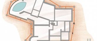
Drawings and dimensions
The product diagram is a template and allows you to visually estimate how the stages of the manufacturing process of the future tool are located. The dimensions of the garden auger can be as follows:
- handle (if the product is handmade) - crossbar 0.5 m long;
- rod – about 1 m (without additional sections);
- the diameter of the disk cut into pieces is 15-25 cm (reference point is ready-made saw blades for an angle grinder);
- tip length – up to 10 cm (peak or drill);
- the distance on the axis given for the installation of disks (taking into account the slope), after a peak or drill - up to 15 cm;
- The upward tilt angle of the knives is up to 30 degrees.
In an auger drill, the length of the “screw” (a monoblade with several turns) can reach up to half a meter. The tilt of the screw stroke can reach the same 30 degrees (at any point of the monoblade). The remaining parts of the auger drill are the same as those of a simple two-blade drill.
The dimensions of the drill for planting seedlings, such as tomatoes, generally coincide with the dimensions of the working part of an ordinary bayonet shovel. Its cutting edges are trimmed so that the bayonet of the shovel goes from round to straightened and pointed at an obtuse angle. The leaf fold is cut off from the opposite (upper) edge. A long (more than half a meter) concrete drill can be welded into the hole from which the handle is pulled out (under the universal hammer drill clamp). It is advisable to use a drill made from a shovel bayonet with a drive, since for manual drilling it requires more effort than the inclined screw of an auger or half-disc of a conventional garden drill.
A drill of any type can be equipped with additional sections. Each of them increases the depth of soil drilling by a meter. These extension sections are used when the owner decides to drill a well for water himself. One such section is used when the ground is soft. These can be posts for fences and other non-permanent structures, buried to 1.4 - 2 m.
Having decided what kind of hole drill you need, cut out a sketch for the blades from cardboard. It made cutting sheets easier and faster.
Advantages of do-it-yourself manual drilling
Manual drilling with self-made devices has the following advantages over automatic drilling methods using special drilling equipment by individuals and organizations:
Cheapness. Making a drill with your own hands from scrap materials and drilling a well without the involvement of third-party assistants, specialists, or organizations is the most profitable option from a financial point of view if other methods of employment in your free time do not bring monetary income.
Versatility. Independent manual drilling work is universal due to the following features:
- Manual drilling in many situations is the only possible option for carrying out work, if entry into the site of special equipment is impossible or the well is located in a built room.
- Narrow borehole channels are laid manually without the use of casing columns of standard diameter, which significantly reduces the cost of organizing and equipping water supply on an individual site.
- Drilling is carried out manually to a depth of 5 to 35 m, which corresponds to the characteristics of an Abyssinian and sand well.
- The drill made can be used for other economic purposes, if it is necessary to make holes in the ground - when constructing fences, planting garden plants, installing pile foundations and other household work. If it is no longer needed, the structure can always be disassembled and used on the farm at your own discretion.
Complete set of hand-held twist drill, factory-made.
Flexibility of use . Depending on the depth of the water layer, the quality of the soil and the dimensional parameters of the borehole channel, various drilling technologies, designs of drilling devices or combinations thereof are used. With individual manufacturing, there is always the opportunity, through experimentation, to independently make a drill for a well, the most convenient and effective for specific conditions.
Work can be carried out at any time convenient for the owner, without reference to the season, time of day, weather, hired specialists or organizations. If electricity is not supplied to the area being developed, wells can be drilled manually and mechanically without its presence.
Of course, you will have to pay for the low cost of the manual method in the speed of work and intense physical labor, the latter being to some extent useful in terms of improving health.
Pipes and couplings for threaded connections
Modifications
Before making your own, you need to consider various models of hand-held eartheners. Taking a suitable design as a basis, one should determine its characteristics: productivity, cutting force, ability to work with hard soil. Perhaps for individual use you will have to make a combined device that combines successful solutions from several models.
Basic diagrams of auger tools
The basis of the earth rotor is the screw part - the auger. It is made welded from thin-walled steel disks. The latter are cut from the center to the outer diameter and bent. As a rule, from 1 to 4 rings are taken to make a screw. The volume of soil that can be extracted in one pass depends on their quantity. However, with a larger number of rings, the drill is more difficult to rotate and remove from the ground. The soil is cut by the auger itself or additional blades. In the first case, the working edge quickly dulls on plant roots or stones. And the blades are made of durable steel and do not require periodic sharpening.
Methods for connecting drill pipes
To drill long distances, the drill is extended under water using hollow steel pipes of standard diameters 21.3, 26.8 and 33.5 mm with a length of 1500 to 2000 mm, which are connected to each other in the following ways:
Threaded. In this technology, for connection, an external thread is used, which is cut at one pipe end, and an internal thread on transition couplings, which are short cylindrical sections with a diameter corresponding to the lower point of the pipe thread notch. Cutting is carried out manually with dies using die holders according to the old Soviet method or with modern, more convenient devices - cutters. After applying threads to the inner side of the transition couplings and the outer shell of the pipes at one end, a coupling is welded to their other edge, and extension is carried out by screwing subsequent pipes into the couplings of the previous ones.
Bolt and threaded coupling . With this method, a large diameter bolt is welded to one end of the pipe, and a long nut in the form of a coupling with an internal thread corresponding to the external thread of the bolt is welded to the other, and when connecting the pipe elements, they are screwed onto each other until they stop. The technology is reminiscent of joining factory-produced drill rods; factory connecting heads can be welded or screwed to threads instead of bolts and couplings.
Bolting and heads for drill rods
Pin . Joining pipes using a pin is the most optimal method, ensuring high speed of connection and disassembly of extension rods. To implement it, an internal coupling is welded to one side of each pipe, the next pipe is put on it and holes are drilled in them at some distance from the edge. Then a pin is inserted into the through channel of the two joined pipes, preventing them from being separated.
The disadvantage of pin fastening is the possibility of falling out of the holes; the easiest way to eliminate this disadvantage is to use a threaded bolt with a nut for fastening. True, this solution is ineffective for a quick connection; moreover, when used in the ground, the thread is constantly clogged with dirt, which significantly slows down the assembly and disassembly of the extension pipeline. It is more effective to use a pin with a lock, which is a rotating plate embedded in its end, similar to the design used for assembling scaffolding. But this system also has the disadvantage of using individual elements that can be lost; also, when the extension rod pipes rotate in hard soil, there is a high probability of deformation and damage to the weakened pin ends with limiting plates.
Pin designs
The best method for solving problems associated with the disadvantages of pin connections is to use a special design in which a U-shaped plate with an inserted pin is welded to the pipe opposite the through hole, and a restrictive pin is inserted into its body through a through radial channel. The limiter prevents the pin from being lost and falling out of the assembly, and is also an element with the help of which the pin is moved along the through hole, connecting and disconnecting the pipeline. Also, the outer U-shaped steel plate protects the pin and stop from damage when rotating in the ground.
If the above design seems too complicated to be manufactured at home, a good option is to purchase a factory-made pin for attaching soil drills, which is a bolt with smooth walls, in the head of which a hole is drilled and a rigid wire stop is inserted, which goes around the pipe and is put on on the other side to the end of a smooth-walled bolt.
Option for quickly connecting a borehole drill with pins
Types of motor drills
- lungs;
- heavy.
The former are more compact and cheaper. One operator is enough to control them. They are equipped with an engine with a power of up to 3 liters. With. The most common engines are 1.5 -2 liters. With. and a working volume of 33?40 cubic meters. cm.
Their work is limited to loose sandy soils, loam and black soil. The maximum depth of the hole is 1.5-2 m.
When working with heavy soils, clays, and rocky soils, heavy motor drills are used. They are equipped with engines with power starting from 3.5 liters. With. and they require two operators to operate them. Some heavy motor drills are mounted not on a frame, but on a trolley. Then one manager is enough.
Heavy motor drills can be equipped with a hydraulic drive, which is completed with:
- a hydraulic pump that provides hydraulic fluid pressure;
- a hydraulic motor that provides low-speed rotation of the shaft and drill with auger;
- distribution system that provides reverse by switching hydraulic fluid supply valves.
The hydraulic drive is an extremely reliable system, as it does not contain a large number of moving moving parts and provides sufficient power and torque to operate large diameter augers on heavy soils. However, such systems are very expensive for non-industrial use without constant work. Heavy motor drills with hydraulic drive can handle drilling to a depth of up to 5 m.
The presence of reverse and several gears are extremely useful properties for motor drills, as they allow you to avoid jamming of the drill with the auger and select the optimal operating mode.
Preparing for independent drilling
Before making a drill for drilling a well with your own hands, you should determine the following factors:
- Estimated depth of the water basin . If the water layer is located at a depth of no more than 10 m, the well can be awakened by any of the 4 methods above. For water intake with a surface electric pump, a small channel cross-section is sufficient, so it is more rational and simpler to use driving technology using a needle drill or screw penetration with a small diameter drill. If you plan to use a submersible pump in a column of standard casing pipes, a bailer or spoon-type structure is made. For drilling to great depths, as well as to shallow ones, there are no competitors to auger hydraulic drilling in terms of speed and efficiency; the use of the percussion-rope method with a bailer or a spoon drill is significantly inferior in time to auger drilling using water and may turn out to be economically unprofitable due to high physical stress and significant loss of time.
- Well diameter . For water intake from depths greater than 9 m from the surface level, you will need to use a submersible electric pump, which requires the use of a large diameter casing; in this case, drilling can be carried out using any of the above methods. An effective option for sinking clay structures is to use drilling in the casing, in which water is poured into it, and the soil in the form of liquid mud is extracted out with a bailer or spoon device.
Homemade spoon drills
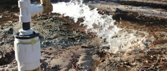
Do-it-yourself manual hydraulic drilling of water wells
First you need to identify the aquifer. The number of casing pipes and the complexity of drilling a well depend on its depth. Land authorities will help you find out the soil characteristics. Preparatory work includes determining the source of water and the supply of liquid for work.
Manual hydraulic drilling includes the following steps:
- Pouring water into the pit and mixing it with clay.
- Turning on the motor pump. The flushing fluid flows through the hoses to the drilling rig. Then the liquid flows into the first pit. There the water is filtered. The pure substance is sent to other pits.
- To reach the aquifer, additional rods are used.
- Next, you need to remove the rods and install casing pipes.
For this purpose, casing pipes with a thickness of 6 mm are used. Pipe material may vary. Plastic, steel, asbestos cement are used.
Casing pipes should be equipped with filter units. Then the water will be cleaner and of higher quality. Next, you need to flush the well again.
It also provides for washing when the float passes, so that the well does not collapse and is covered with sand. For this purpose, CMC wallpaper glue is used. But if you pump the water until it is clean, you can put a mesh on the filter pipe.
Manufacturing of borehole drills
After determining the drilling method, they begin to independently manufacture a drilling device; for this you will need:
- Household welding machine with steel electrodes.
- Angle grinder for cutting metal.
- Cuttings of steel plates, pipes, used discs for stone, concrete, wood for making a drill.
- Pipes 1500 - 2000 mm long for lowering the drill to a depth, a thread-cutting unit with dies, adapter couplings purchased or prepared for threading.
- Strong steel cables, tripods, homemade winches for lowering and lifting loads, bailers, spoon devices into the borehole.
- Power tools to speed up drilling operations - hammer drill, drill, jackhammer.
Varieties of homemade augers
Auger or spiral drill
A factory-made auger drill is a piece of metal rod or pipe, around which a steel strip is welded in a spiral, and at the end there is a pointed tip. The spiral-shaped tape breaks off near the tip and has a different number of turns; during operation, soil falls into the space between the turns and when the auger is removed, it is thrown onto the surface of the area.
It is quite difficult to make such a device at home due to the great difficulties in bending a steel strip about 2 mm thick into a spiral with a small radius, so they use a simplified design of an auger drill, consisting of a small number of turns. The best option is to make a homemade screw drill for a well with your own hands from used metal discs for an angle grinder. To do this proceed as follows:
- Take a piece of metal pipe with a standard outer diameter of 21.3 mm, attach a pre-prepared tip to its end, it can be a pointed steel plate cut in the shape of a triangle, the tip of a spear, or a ribbon spiral. The tip is fixed by welding, if a multifunctional design with a change of tip is intended to be used, it is inserted into the cut of a pipe or steel pin, then bolted through the through holes.
Auger drill - manufacturing stages
- A standard disc for an angle grinder has a seat diameter of 22.2 mm; when used as a working surface for a drill, it is cut in the radial direction from the edge to the center and the edges are moved in different directions at an angle of 30 degrees so that a fragment of a spiral is obtained. In this case, the internal diameter of the disk when bending slightly decreases and ensures mating with the outer diameter of the pipe of 21.3 with a small gap sufficient to accommodate the metal from the electrode with an internal rod diameter of about 5 mm. As a spiral fragment (disc), used steel circles for cutting stone, concrete, and wood with a serrated edge with a standard outer diameter of 115 mm are used; sometimes 1 or 2 discs are additionally welded, providing a larger excavation.
- At the end of the auger drill pipe, a thread is cut or a threaded coupling is welded to it for connection with subsequent pipes; due to its small diameter, a through hole for the handle is not drilled in the longitudinal direction, but this operation is carried out with sections of pipes that will lengthen the structure.
Note: A homemade spiral drill of small diameter is used for the fastest mechanical penetration of a borehole channel in hydraulic drilling, while water is supplied to the tip of the drill through a system of extension steel pipes, which are connected to each other by threads using couplings.
Needle
The needle drill is designed for forming narrow and shallow borehole channels; it is often left in the well, which determines the technology for its independent production. A needle borehole drill and penetration is done in the following way:
- They take a thick-walled steel pipe 1500 - 2000 mm long, weld a pointed metal tip of a tetrahedral, conical shape at one end (you can use a peak from a hammer drill) and drill a series of holes in the walls for water access to a length of about 1500 - 2000 mm from the tip. On the other side, a pipe section of a smaller diameter (internal coupling) is inserted into the pipe to connect to the next pipe and secured by welding.
- A rigid clamp is fixed on the surface of the first pipe, onto which a load is then periodically lowered and moved along the pipe surface - as a result, the needle is driven into the ground. After lowering the joint point near the surface of the earth, the pipes to be connected are welded from the outside, the clamp is moved higher along with the load onto the next pipe. Sometimes they use a metal plate welded to the outside of the casing pipe, which is struck with a load; after lowering to the required distance, the shock pipe is removed, replaced with a casing one, and the process is repeated further.
- Upon completion of the work, the pipeline is cut at the required distance from the ground, a thread is cut at the end and an electric pump is connected through adapter couplings, while the steel pipeline simultaneously serves as a casing column and a pressure hose supplying water.
Hydro drill drawing
I was guided by the fact that the device should be easily repeatable and could be made by anyone who was interested in this topic. You will need 2 corners, 75 mm wide on one side, wall thickness 8 mm and 30 cm long. And 2 corners 65 mm long, wall thickness 5 mm. A pipe with a diameter of 32 mm is also required.
The cutting part of the drill will be under a 2 cm cone. We cut it and sharpen it to a cone. On the cutting edge we make a marking of 17 mm from each edge. It is necessary to cut it so that the pipe does not reach the cutting edge by about 10 cm. To make the holes for the water jet larger, all that remains is to use a grinder to cut out the inside of the corner a little, and at the same time we will make a chamfer on each edge and on the outside of the corner. To prevent the drill from clinging with sharp edges, when we pull it out, the sharp edges of the corners must be cut off. Next, we wind a millimeter rope around the pipe to ensure a millimeter gap and intercept it by welding. For more thorough welding, remove the pipe.
Now we need 20 pieces of inch metal pipe, 2 meters each. The ends must be chamfered so that threads can be cut. Except for one, because this one edge will be welded to our drill. On the one hand, we will cut the threads to half the length of the coupling, immediately screw them on and secure them a little with welding to prevent unwinding during the drilling process. On the other hand, we will cut the threads a little larger, approximately the entire length of the coupling, and screw on the nuts that protect the pipe from unwinding. !!! Regarding thread cutting, I recommend going to a turner. since this is a difficult task for such a pipe diameter.
On the pipe that did not have a thread, we put our drill on it, set the same gap everywhere and scald it as shown in the photo.
Let's prepare the ribs for centering the drill. Corner 65 by 65 mm, two pieces of 15 cm. To avoid clinging, cut 3 cm on each side. Now we need to weld it to our drill on different sides, about 30-50 centimeters from the edge.
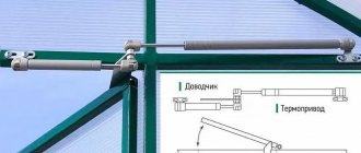
Advantages of a homemade motor drill
You can make a motorized drill yourself for those who have good metalworking skills and are familiar with turning. Costs will be minimal if you already have a chainsaw. It is enough to purchase an adapter for a screw auger and a gear worm gearbox. The gear ratio of the latter must be at least 1/55. There is no need for mechanical transmissions or couplings.
This technique has obvious advantages over professional tools:
- saving money;
- the ability to quickly and easily perform site improvement tasks;
- due to the low power of the motor, there is no need to additionally involve a specialist;
- homemade drill - light and mobile.
Some believe that a non-professional gas drill cannot be classified as a full-fledged technique, because the maximum possible diameter of the hole is no more than 150 mm. This value is quite sufficient for solving everyday problems. Of course, such a technique is not suitable for large-scale production.
Recommendations
If we compare a device assembled with our own hands and a purchased unit, the first option is considered more budget-friendly. For carrying out earthworks on a personal plot, a homemade unit will be quite sufficient, provided that there are no too hard soils.
When assembling a motor drill yourself, it is recommended to follow safety precautions and use only reliable and durable tools and materials. Experts also advise you to familiarize yourself with the structure of a motor drill, the design of simple mechanisms and the operating principle of the future tool.
Instructions for working with a motor drill
To drill a hole, a person who works with a motor drill must first of all follow safety rules and read the instructions for the device.
- Each motor drill has handles that must be grasped during operation. The motor drill requires vertical installation on the soil surface. After this, you should turn on the device.
- Gradually, in the process of deepening the head, the soil is cut off and the motor drill is immersed.
- To improve performance, periodically pull the device upward to move away and eject soil.
- The main drawback during operation is jamming. For example, if a motor drill hits a stone or other hard surface. Some models have a protective engine shutdown function if such an incident occurs.
- But in any case, a person who works with a motor drill must be attentive to the work, study safety precautions and have enough effort to hold the device.