For what purposes is the valve used?
In order to avoid situations with battery rupture, two devices are used in the heating system: a pressure gauge and a valve. The first device is designed to visually indicate the pressure that is in the system at any given time.
As for the valve for releasing excess pressure of water or other coolant, it serves to automatically prevent an accident. This helps a lot if at the moment of a pressure surge people do not see the readings.
As is clear from the name of the device, it is obliged to relieve the system of excess pressure during its operation. But not everyone understands what excess pressure is.
The fact is that a certain amount of bar in the system is always present for which the elements are designed. When purchasing, they also take into account possible excess pressure so that pipes and radiators can cope with it.
However, the pressure does not always exceed the limit that was taken into account when installing the equipment. So, the valve begins to release pressure as soon as it exceeds a constant norm.
If the excess reaches the limit of what is excessively provided, then the pipes will simply begin to burst.
Thus, the valve protects against the possibility of an emergency condition. It is used not only in the heating system, but wherever there is pressure in the system.
Purpose and scope of application
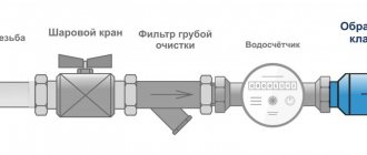
The valve is used to protect premises and equipment from excess pressure of the medium transported through pipes:
- heating systems - to remove excess coolant volume from heating devices resulting from thermal expansion;
- water supply - to reduce the risk of water hammer;
- ventilation - ensures air movement only in a given direction;
- gas supply, compressed air supply, fire extinguishing and other types of pipeline structures - in case of emergency situations.
What does the device consist of and how does it work?
The relief valve is a device in a metal casing made of brass or stainless steel. Inside the device there is a rod with a spring connected to a special membrane, on which the working medium directly presses, but under normal hydrodynamic parameters it is opposed by a spring that keeps the membrane closed.
The equipment operates on the principle of direct action: the working medium, as the temperature rises and the volume increases, presses on a spring, which opens the hole and releases excess hot water until the pressure returns to normal. After this, the spring presses on the membrane in the opposite direction, blocking the outflow of the working medium.
We recommend that you read: Using paint for the surface of galvanized pipes
Thus, as soon as the water pressure in the system rises above a critical level, the spring compresses, opening a passage hole to discharge excess water. After briefly draining the hot water, the pressure in the system normalizes and the spring is activated, closing the valve.
In addition to the automatic mechanism based on spring actuation, the valve has a handle for manual water release, which allows the user to independently drain a small amount of heated coolant when the pressure gauge readings approach critical.
Important! The dumping device is installed only on the supply section of the heating system no further than 50 cm from the boiler. Do not install any foreign devices between the boiler and the valve (taps, valves, diverters, etc.)
Professional installation advice
Even such a simple procedure as installing shut-off valves is based on the implementation of certain rules. For example, the design of a room often requires camouflage of the pipeline and security group.
You can hide devices, but subject to three conditions:
- the length of the flexible line or pipe from the fuse to the tank should not exceed 2 m, otherwise there will be excessive additional pressure on the valve spring;
- the ideal installation of the fuse is directly to the boiler fitting, and if this does not work, then installing a tee is still excluded;
- To service the fittings, a technical hatch should be equipped.
Many people worry when they see drops of water on the valve connection. This is a normal phenomenon and indicates that the device is working properly.
From time to time, small pressure surges occur in the line, which provoke a minimal discharge of liquid. You need to worry when water either does not appear at all or pours continuously.
The line length between the water heater and the fuse should be minimal. This is necessary not for aesthetic reasons, but so as not to create additional pressure in the pipes
It should be remembered that independent modernization of safety devices is strictly prohibited. If you need a 0.8 MPa valve, then you need to purchase just such a new product, and not try to somehow remake or adjust the 0.7 MPa device.
If there is any doubt about the functionality of the safety valve, you should dismantle it and check whether the spring or seal is clogged. Are you having problems with your water heater itself and don’t know what to do? We recommend that you familiarize yourself with common boiler breakdowns and repairs. If you lack skills, invite a specialist from the service center.
Advantages and disadvantages
The relief valve has the following advantages:
- eliminates water hammer and pressure surges;
- prevent the appearance of air pockets in the liquid media transportation system;
- simple design that is easy to maintain and repair;
- relatively low cost;
- possibility of automatic control and pressure release;
- simple installation technology;
- unpretentiousness to operating conditions;
- do not require frequent maintenance.
Flaws:
- presence of operating error;
- increased wear of critical parts;
- limited service life.
Simple valve design
Why might a valve leak?
The pressure relief valve in the heating system can leak for various reasons.
In some situations, this is an acceptable natural process; in other cases, a leak indicates a malfunction of the device. Leakage of the protection valve can be caused by the following reasons:
- Damage to the sealed rubber cup or disc as a result of repeated use. If during repairs a replacement part cannot be found on sale or is not included in the package, you will have to replace the device completely.
- In spring types, the opening of the side drain pipe occurs gradually; at borderline pressure values or short-term surges, the valve may partially operate and drip, which does not indicate its malfunction.
- Leakage can be caused by incorrect settings or malfunctions of the expansion tank - damage to its membrane, air escaping through a depressurized housing or a damaged nipple. In this case, sharp pressure surges are possible as a result of water hammer, causing periodic short-term leakage of coolant through the safety valve.
- The cause of leakage in some adjustable valves is fluid seeping down the stem through the top during actuation.
- If a back pressure is created at the outlet pipe above the device's response threshold, a leak will also occur.
Appearance, cost of some brands of drain valves
The safety valve of steam boilers is designed to protect them from excess pressure in the system caused by various factors, and is a mandatory element when operating this type of equipment. There is a wide range of safety devices on sale from Chinese, domestic and European manufacturers, which are characterized by a relatively low cost. When purchasing, it is rational to choose a protective group from several devices, which additionally includes a pressure gauge and an air release valve.
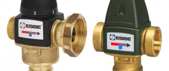
Operating principle
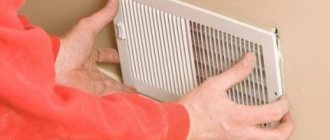
Most ordinary users faced with closed water heating systems are familiar with only one type of safety valve - a simple spring valve with a fixed setting, shown in the photo. The reason is clear - these elements are installed everywhere on any boilers, since they are part of the safety group along with a pressure gauge and an air vent.
Note. Wall-mounted heat generators operating on electricity and natural gas are equipped with safety elements from the factory. They are placed inside the case and are not visible from the outside.
Let's understand how a regular emergency valve works, shown in the diagram above:
- Under normal conditions, the diaphragm, attached to the stem and supported by a spring, sits tightly in the seat and seals the passage.
- If the coolant overheats, it expands and creates excess pressure in a closed system, partially compensated by the expansion tank.
- When the amount of water pressure reaches the valve response threshold (usually 3 Bar), the spring is compressed under its influence and the membrane opens the passage. The boiling coolant is automatically discharged until the spring has enough strength to close the flow area again.
- In the event of an emergency, the owner of the house can relieve excess pressure himself by turning the handle at the top of the product.
A few words about where the relief valve is installed along with the safety group in a closed heating system. Its place is on the supply line in the immediate vicinity of the boiler (recommended no further than 0.5 m).
The safety unit is always installed on the heater flow line
Important point. It is prohibited to install taps, valves and other shut-off devices on the pipeline leading from the heat generator to the safety elements.
You should not tightly connect the pipe of the product to the sewer - wet spots or puddles will indicate the valve has been activated and problems in the heating network. For example, the expansion tank failed or the circulation pump malfunctioned when working with a solid fuel boiler (the electricity may have been turned off). Often the device begins to leak due to debris getting between the seat and the plate. More about his work is described in the video:
Watch this video on YouTube
Additional information. Masters and installers call spring relief valves blasting valves because the pressure of the coolant compresses the spring and causes the membrane to explode. Do not confuse them with explosive elements installed on the chimneys of industrial boiler houses that burn natural gas.
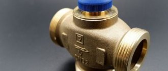
Design features and operation
Consider in detail how a safety valve with a spring works. Its body is made using hot stamping technology from brass. The main working element is a spring, which presses the membrane that covers the seat.
Valve with spring mechanism
On the rod connected to the handle there is a washer that serves as a stop for the upper end of the spring. Using the handle, the position of the washer and, accordingly, the clamping force on the membrane are changed. The spring is made of steel; the handle, seals and membrane are made of polymer materials.
The operating principle of the device is as follows: as long as the parameters of the coolant do not exceed the specified maximum permissible values, the membrane tightly closes the hole. When the situation is close to an emergency, as the pressure increases, the superheated coolant (a mixture of water and steam) lifts the membrane, overcoming the resistance of the spring. Thanks to this, the steam-water mixture is discharged out through a special hole. After dumping the excess volume of the steam-water mixture, the pressure in the pipeline decreases, and the coolant again loses the ability to compress the spring.
Note! The device can operate cyclically if the boiler is operated at maximum power, heating the coolant to 90-95 degrees. This mode of operation has a negative impact on the protective device - after several operations the blast valve begins to leak due to loss of tightness
Types of overpressure relief valves
There are several generally accepted classifications of safety valves. Depending on the method of action, there are:
- direct-acting valves - devices are activated by direct action of the working medium on the spring mechanism;
- indirect action - operate under the influence of an external pressure source (hydraulic fluid or electric drive).
Based on the type of load on the membrane, the device is divided into the following types:
- cargo - the most common mechanism for adjusting the working pressure in the system;
- spring - the pressure of the working medium is counteracted by a lever that presses on the rod, holding it in the closed position;
- lever-spring – hybrid devices equipped with a spring and a lever mechanism;
- magnetic spring valves are indirectly acting valves equipped with an electromagnetic drive.
Modern manufacturers offer other types of excess pressure relief valves.
For example, there are thermal relief valves on the market that respond not to an increase in pressure, but to an increase in the temperature of the working environment. They may have a remote or built-in temperature sensor, which operates on the basis of a heat-sensitive liquid located in a bellows.
When the water temperature heats up to 95-100 degrees, the liquid in the capillary tube of the sensor flask puts pressure on the bellows, which opens the rod and drains the superheated water to normalize the pressure.
We recommend that you read: Which ball valves are best for water supply
According to the control method, the valves are divided into two groups: manual and automatic - they are controlled, respectively, manually or are activated automatically when the pressure of the working medium increases. In addition, there are regulated and unregulated. Adjustment allows you to set any water pressure threshold.
Depending on the type of working medium, there are water and air. The former remove excess liquid, the latter discharge excess gases from the system, preventing airing of circuits in closed heating systems.
There are also control valves equipped with a built-in thermostat, which changes the throughput of the device, slightly opening or completely blocking the outflow of the working medium. Such devices are usually installed at the entrance to the heating radiator in the room.
Element with remote sensor
The product is the same spring mechanism, built into a housing with two pipes for connection to the supply line and discharge into the sewer. The rod that opens the plate and the path for the coolant is moved by bellows (2 groups - main and reserve). When the water overheats (from 95 to 100 °C), they are pressed by a heat-sensitive liquid coming from the sensor flask through a capillary tube. The design of the safety element is shown in the figure:
The temperature valve is included in the piping of a solid fuel boiler in three ways:
- with cooling through the water circuit of the heat generator;
- the same, through a special emergency heat exchanger;
- coolant discharge with automatic replenishment.
The first diagram, shown below, is used for double-circuit heating systems that heat water for domestic hot water. When a sensor mounted under the casing of a TT boiler acts on the mechanism, hot water from the circuit is drained into the sewer, and cold water from the water supply takes its place. Whatever the causes of the accident, such a flow system will quickly cool the boiler jacket and prevent consequences.
The DHW coil of a double-circuit boiler can serve as both a heater and a cooler in case of overheating. For protection, just connect the thermal valve according to the diagram
Note. The publication uses diagrams from the CALEFFI brand, taken from the manufacturer’s official resource.
The second scheme is intended for heat generators with a built-in emergency heat exchanger for cooling in case of overheating. Such units are produced by European brands Atmos, Di Dietrich and others.
For an example of connecting a discharge element through a standard heat exchanger, see the video:
Watch this video on YouTube
The latter scheme can only be implemented in conjunction with an automatic make-up system, since here the valve discharges coolant and not cooling water.
As you can see, the manufacturer allows the installation of two emergency devices - for pressure (safety group) and for temperature (relief valve)
Warning. It is not recommended to use automatic make-up for wood-burning heaters with a cast iron firebox. The latter is afraid of temperature changes and can crack if a large amount of cold water is supplied to the return line.
Combination valves with system make-up
This bright representative of emergency valves is similar in principle to bypass valves and performs 3 functions at once:
- Discharge of overheated coolant from the boiler tank based on a signal from an external sensor.
- Efficient cooling of the heat generator.
- Automatic replenishment of the heating system with cold water.
The picture above shows the design of the product, where you can see that there are 2 plates installed on one rod, which simultaneously open 2 passages: the boiling coolant is discharged through the first, water flows through the second in the opposite direction and replenishes losses. The connection diagram for a combined bypass valve with a solid fuel boiler looks like this:
Note. If it is necessary to use such a device to cool a TT boiler with a cast iron heat exchanger, then the flow must be organized through an open expansion tank or an indirect heating boiler.
A bypass valve with a triple outlet works on the same combined principle, only it is built directly into the coolant supply pipeline near the heating unit. The bellows is located in the part of the body placed in the pipe. The discharge is carried out through the lower pipe, and a water supply and a make-up line are connected to the two upper ones. Such products are used when there is not enough free space in the boiler room.
This relief valve is designed to be installed in the supply line.
Price
The price of the mechanism depends on its type, characteristics, materials and workmanship, quality of processing and manufacturer's markup.
| Model | Allowable pressure, bar | Cost, rub. |
| Spring | ||
| WATTS SVH 3/4″x1″ | 3 | 690 |
| VALTEC ½ (VT.0490.IG.0460) | 3 | 550 |
| VALTEC ½ (VT.1831.N) – adjustable | 12 | 915 |
| Lever-load | ||
| Pregran KPP096-01 Du15 | 16 | 19 200 |
| 17s28nzh Du50 Ru10-16 | 16 | 12 000 |
| Thermal relief valves | ||
| Watts STS 20 art. 02.32.120 | — | 4 900 |
| Protherm Caleffi 544 – 1/2″ | — | 12 000 |
InstructionsBoiler room equipmentSafety fittings
How to choose a relief valve
Of course, in terms of purchase and installation costs, a traditional blasting valve will be cheaper than temperature devices. It will easily protect a closed heating system connected to a gas, diesel or electric boiler, because in the event of an accident they stop heating almost instantly. Another thing is a heat generator using wood and coal, which cannot go out immediately.
To successfully select a thermal relief or overpressure valve, follow these guidelines:
- When using any energy carriers other than solid fuel, feel free to buy a regular blasting device.
- Study the documentation of your heat source or boiler (depending on what needs to be protected) and select safety fittings according to the maximum permissible pressure indicated therein. Most heating equipment is designed for a limit of 3 Bar, although there are exceptions - Lithuanian Stropuva boilers can withstand only 2 Bar, and some Russian units (among the inexpensive ones) can withstand 1.5 Bar.
- To effectively cool wood-burning heat generators in the event of an accident, it is better to install one of the thermal relief valves. Their maximum operating pressure is 10 Bar.
- In open systems with a TT boiler, pressure relief is useless. Select a safety product that operates at a coolant temperature of 95–100 °C, suitable for your unit and recharge method.
Advice. Refrain from purchasing cheap safety valves from China. Not only is it unreliable, but it also leaks after the first explosion.
Watch this video on YouTube
In addition to models with fixed settings, there are valves with adjustable settings on sale. If you are not a heating professional, then you should not buy them, and there is no particular need.
Manufacturers
The greatest demand is for security groups from Valtec and Watts. Their products are distinguished by high quality workmanship and reliability. For example, VT.460.0.0 from Valtec is used for heating systems with a nominal pressure of up to 10 bar. The maximum temperature of use should not exceed +120°C. Steam, water or a special liquid can be used as a coolant.
The emergency valve has a fixed setting of 3 bar. The body of the safety group is brass, nickel plated. The thread for connection is internal, size 1″. The cost of the VT.460.0.0 group starts from 1,700 rubles.
Security Groups from Watts
The WattsKSG-MS security group has similar characteristics. The body is made of brass, but unlike the previous device, it is located in a heat-insulating casing. The emergency valve response threshold is 3 bar.
When installing the safety group and other parts of the heating system, you must strictly follow the instructions supplied with them from the manufacturer. Because if installed incorrectly, the system will not work properly, or an error made during installation will lead to its breakdown.
Rules for installation and operation of the device
To maximize system protection from overpressure, you must follow the rules for installing and operating the relief valve:
- the connection is made at the outlet pipe of the heating equipment;
- for installation, select the highest possible point of the pipeline;
- the discharge pipe must be connected to a discharge channel connected to the sewerage system;
- the diameter of the valve opening must correspond in area to the internal diameter of the pipe;
- the location of the control device is located in a place accessible for maintenance;
- It is recommended to use quick-release connections;
- if you need to connect pipes after installed valves, then the diameter of the outlet part must be equal to or exceed their cross-sectional area;
- when installing two pressure relief devices, the cross-section of the pipe must exceed the area of the passage openings by a total of 25%;
- It is prohibited to install tie-ins and branches of communications between the boiler and the valve;
- after installation work, you need to make sure that the valve opens at the specified parameters;
- Maintenance should be carried out strictly in accordance with the manufacturer's requirements.
During long-term operation, blockages form on the internal surfaces, which can negatively affect the valve response time. It is important to use special solutions to clean them. Alcohol or vinegar solutions are suitable for these purposes.
If leaks are noticed on the body, then installing plugs is strictly prohibited, as this can lead to emergency consequences. It is necessary to quickly replace the device by selecting the correct parameters.
To monitor the condition, configure and check the functionality of the valve, you need to use the readings of pressure gauges, temperature sensors and other instruments. This will allow you not to involve specialists, but to solve all the necessary problems yourself.
Tips for choosing the optimal model
Before choosing a specific safety equipment, you must familiarize yourself in detail with the technical characteristics of the boiler installation.
The operation of the safety valve is negatively affected by sub-zero temperatures. Therefore, a fairly important characteristic for the device is the presence of frost protection
Do not neglect to study the manufacturer’s instructions, which indicate all the limit values.
Several criteria play a decisive role in choosing a heating device:
- Boiler performance.
- The maximum permissible medium pressure for the thermal power of heating equipment.
- Safety valve diameter.
You should check that the pressure regulator in the device has a range that includes the parameters of a particular boiler. The response pressure should be 25-30% greater than the operating pressure required for stable operation of the system.
The higher the operating pressure, the less time the device should spend on operation. The gap between the pressure at the start of movement and when the shutter is fully opened should be 15% for a nominal value less than 2.5 atm, 10% for higher parameters
The diameter of the safety valve cannot be less than the connector of the inlet pipe. Otherwise, constant hydraulic resistance will not allow the fuse to fully perform its immediate tasks.
The optimal material for manufacturing equipment is brass. It has a low coefficient of thermal expansion, which prevents destruction of the housing from exposure to strong pressure.
The control unit is made from heat-resistant plastic materials that maintain the required rigidity even when in contact with boiling liquid.
Installation Features
When installing a water relief valve, you should consider not only its characteristics, but also the work performed by the expansion tank. If it does not respond to increased pressure in the system, the fuse should operate to allow excess fluid to escape. Following the installation rules, the valve location should be at a distance of 30-40 cm from the boiler outlet pipe, and a pressure gauge should be built between them. Its readings serve as information about the condition of the heating circuit. Relief valve installation rules:
- 1. It is prohibited to install shut-off equipment in front of the device - valves, taps, etc.
- 2. To remove excess water, a drain tube is placed at the valve outlet. To do this, you can use a return or sewer connection.
- 3. The safety valve must be located at the highest point of the closed heating system.
In addition, the working condition of the mechanism should be checked regularly. For spring models, soldering of the plate to the walls of the housing may occur. This acts by exceeding the maximum pressure mark, which affects the timely operation of the valve in the heating system, due to which the device may not open the hole for the liquid to exit.
This often concerns the operating conditions of the heating reset fuse, and not the principle of its operation. But even with careful installation, unstable operation of the product may occur. If the emergency device is triggered frequently (6-8 times), it is recommended to replace it. This means that the mechanism has become unusable - the spring and plate have worn out. When installing a safety valve, the following should be taken into account :
- to what extent do its technical characteristics correspond to operational ones;
- correct connection;
- When installing, you should use traditional tow for pipes; FUM tape (fluoroplastic sealing material) does not withstand temperature effects, which can cause leaks.
It is important to know that if the valve is leaking, you cannot put a plug on it. This will lead to an emergency. You should purchase a new device that matches the operating water pressure and replace the old one.
Functions
Safety valves for water supply and heating systems prevent pressure from rising above their activation level and protect pipelines, fittings and other fittings from damage.
It is worth clarifying: they are not used in cold water supply systems, centralized hot water supply systems with water supplied from heating mains and central heating. Club members - hot water supply with water preparation in a storage water heater (electric boiler or indirect) and autonomous heating.
DHW circuit with indirectly heated storage water heater
DHW
Any type of storage water heater must be equipped with a check valve at the inlet.
Why?
Yes, simply because without this valve, water will pour out of the boiler when the main water supply is turned off and reset. You see, its inlet pipe opens into the tank just above the bottom level: such a device allows you to achieve stratification of water according to temperature.
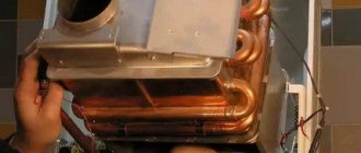
Electric boiler design diagram
Please note: in addition to financial costs, discharging water from the tank will mean a high probability of leakage from the heating elements of the electric boiler.
Now imagine what will happen after filling and turning on the boiler, separated from the cold water supply by a check valve.
- The water temperature will begin to rise;
- As it heats up, its volume will begin to increase, in full accordance with the laws of physics;
Volume growth when water is heated
- An increase in the volume of almost incompressible liquid in the confined space of the tank will cause a rapid increase in pressure.
This is where the safety valve installed on the water supply comes to the rescue: it will release excess water into the drainage and thereby reduce the pressure level.
Heating
On heating, our hero is part of the boiler safety group and performs the same function as on hot water supply: it releases part of the coolant when the pressure rises dangerously.
The valve works in tandem with a membrane expansion tank and duplicates its functions: in normal mode, the excess coolant is contained in the expansion tank by compressing the air separated from the water by an elastic membrane. If the pressure continues to rise due to incorrect calculation of the volume of the tank or overheating of the coolant, the valve is triggered.
Solid fuel boiler piping
By the way: installing an expansion tank is also practiced with boilers of significant volume. It significantly reduces water supply costs: without an expansion tank, each time the water in a 300-liter indirect tank is heated from 10 to 70 degrees Celsius, a little over 6 liters of hot water will be drained into the drain.
Tank in the indirect harness
Installation progress
All products designed to relieve excess pressure are equipped with installation instructions that require careful study before starting installation work. First, disconnect the device from the mains and drain the water. Installation sequence:
remove a part of the pipe whose size is equal to the length of the device body;
- cut threads on the ends of pipes;
- cover them with tow or FUM tape;
- screw the valve onto the threaded part of the pipe;
- connect a hose to the second pipe of the product, which will be directed to the sewer;
- tighten the connections using an adjustable wrench;
- seal with a special paste;
- configure the device according to the passport values.
To extend the life of any heating system, you should include a protective group consisting of a fuse, a pressure gauge and a bleeder valve. It is advisable to install additional temperature sensors that turn off heating equipment or turn on an additional cooling system when the temperature of the coolant critically increases.
Required tools and materials
To install the valve you will need:
- adjustable wrench;
- fum - ribbon or tow;
- special paste for sealing joints.
Connection diagram
For example, let's look at the installation diagram of the device in front of the hot water heater in the apartment.
Pressure regulator
The operation of the batteries and the pump is disrupted due to high or low pressure levels. Correct control of the heating system will help to avoid this negative factor. The pressure in the system plays a significant role, it ensures that water gets into the pipes and radiators. Heat loss will be reduced if the pressure is standard and maintained. This is where water pressure regulators come to the rescue. Their mission is primarily to protect the system from too much pressure. The operating principle of this device is based on the fact that the heating system valve located in the regulator works as a force equalizer. Depending on the type of pressure, regulators are classified into: statistical, dynamic. It is necessary to select a pressure regulator based on throughput. This is the ability to pass the required volume of coolant, in the presence of the required constant pressure drop.
Connection
Based on the type of connection, the following types of devices are distinguished:
- Threaded. Used for small diameter pipelines and low pressures typical for domestic systems. Most convenient for installation and dismantling for possible repairs and maintenance.
- Flanged. It is used in medium and large diameter pipelines and can withstand high pressure. More difficult to install/dismantle.
- Welded. The most durable and airtight connection. It is used on main pipelines and especially critical high-pressure systems. The most difficult to install and dismantle.
Flanged and welded connections are rarely used in domestic systems.
Kinds
There are several types of such devices . First of all, they are divided according to the maximum pressure:
- for containers up to 50 l;
- from 50 to 200 l;
- above 200 l.
As a rule, devices of the first and second groups are one-piece. More powerful safety valves are designed to work with high pressure (usually up to 7 bar).
There are models with and without release handle. The first ones are more convenient; they allow you to check the functionality of the device or manually reduce the amount of water in the container.
Device
Typical emergency valve configurations include:
- Housing with inlet and outlet pipes. The working chamber and valve seat are molded into the cast body.
- The closing element is a disk, ball or cone, in the normal position pressed against the seat and closing the passage for the working medium.
- Rod - a rod to which a locking element is attached.
- An elastic element is a spring or (less commonly) a membrane that reacts to the pressure of the medium and, depending on it, changes its position in space. Applies pressure on the locking element.
- Adjustment element. Most often, it is an adjusting screw that changes the elasticity of the spring and the force of its pressure.
The device may contain additional elements, such as an electromagnetic or pneumatic drive, sensors, pressure gauges, control panels, etc.
The selection of a safety device for a specific application takes into account its design and parameters.
Safety valve categories
The pipeline protecting device consists of the following components:
- locking element;
- saddle with built-in bolt;
- power current sensor.
Safety components intended for standard heating systems are produced in different modifications. Directly depending on the conditions of use, the equipment is distributed according to the following parameters:
- type and category of the clamping element;
- the height of the installed closing lift;
- general speed response mode of built-in elements.
Installation errors and possible problems
According to the service departments that come to correct the mistakes of home craftsmen, the following mistakes are most often made:
- Installation of shut-off valves between the protective device and the boiler.
- The valve location is too far from the boiler (more than a meter).
- Skewed, undertightened or overtightened threads.
A number of professional tips for troubleshooting possible problems:
- The valve allows fluid to pass at normal pressure. The reason is most often that it is clogged with rust particles or mineral deposits. It can be eliminated by washing the device in a strong vinegar solution for several hours. Installation of a mechanical cleaning filter is strictly recommended.
- If leakage continues, the gasket may be damaged or deformed. In this case, you will have to replace the entire device.
- If you have an apartment with plastic emergency appliances, it is better to replace them with ones made entirely of metal as soon as possible. The difference in price will be recouped many times over by the increased resource.
It is strictly forbidden to plug a leaking water pressure relief valve, hoping to fix it later. An accident can occur at any time and damage expensive equipment and pipelines.
Controls and technical characteristics
The most widely used emergency valves installed on domestic heating and water supply systems have mechanical autonomous control. They operate independently when the maximum pressure is reached and are adjusted manually. Complex production plants and piping systems use safety valves that can be remotely controlled and adjusted. As a rule, when communication with the control center is lost, such a valve turns into a regular mechanical one.
Excess pressure relief valves, based on their purpose, design, and material of manufacture, have different sets of characteristics.
The main ones are:
- Trigger pressure.
- Reset pressure.
- Performance of the working environment reset channel.
- Response speed.
- Time to return to its original state (if the valve does this automatically).
A specific emergency overpressure relief valve is also characterized by the type of design, weight and size parameters, connection dimensions
Expert advice
- A blasting device with standard technical characteristics allows water to pass through even at low pressure levels when clogged. The problem can be solved by cleaning the body parts. To do this, the product must be dismantled and placed in a container with vinegar for 2 - 3 hours. Then rinse it with water until completely clean and install it in its original place, lubricating the connection area with alcohol.
- If the valve continues to leak even after cleaning, then most likely the rubber gasket resting on the seat is clogged with debris. It is easier to replace such a part than to clean it without deformation. Replacing the valve on the supply pipeline to the boiler can be seen in the video:
- A number of consumers quite reasonably doubt the durability of shut-off valves with plastic parts. They actually have a shorter service life, so it’s better to immediately buy ones with metal components. Such products are on average 100 - 150 rubles more expensive, but they last much longer.
- You cannot simply turn off the device, even if it is leaking. A huge number of heating boilers have failed precisely after installing the plug.
Burst valve for boiler. Calculation
The calculation of the safety device must be carried out in accordance with the methodology presented in SNiP II-35 “Boiler installations”.
Since manufacturers rarely indicate the actual height of the rod lift in the technical specifications, in the calculation this parameter is equal to 1/20 of the seat diameter. For this reason, the valve size as a result of this calculation is somewhat overestimated. In any case, after selecting a device, it is necessary to compare the thermal power of the heating system with the maximum power recommended in the technical description for the selected standard size.
Installation of a safety valve is required to protect the heating system from exceeding the pressure level above the maximum permissible value. For this reason, the calculation of this device should be reduced to calculating the maximum permissible increase in coolant volume and identifying possible sources of excess pressure.
Sources of volume growth can be:
- Overheating in a heat exchange or boiler unit with subsequent vaporization. When vaporizing, a liquid can increase its volume by 461 times, so this factor is the predominant factor when choosing a valve.
- Failure of automatic control of make-up lines of boiler houses and independent heating systems. This may also be a predominant factor in valve selection.
- The coolant, heating up in a heat exchange or boiler unit, increases in volume. When heated, the specific volume increase is from 0 to 100 °C, which is only 4%, so when selecting the size of a device of this type, this is not a fundamental point.
The selected equipment must ensure the discharge of the calculated amount of coolant, according to the most significant factor in the increase in volume.
Peripheral secondary part
A check valve is an element of the heating system, consisting of a plastic or metal base, which performs the function of completely shutting off the coolant supply. This happens when the flow begins to move in the opposite direction. The metal disk is attached to a spring, which is under pressure when the flow moves in one direction, and when it moves in the opposite direction, the spring is activated to block the passage in the pipe. The valve device has not only a disk and a spring, but also a sealing gasket. This component helps keep the disc in place tightly. Because of this, there is practically no possibility of pipe leakage. Butterfly valves are widely used in domestic heating systems.
Let's look at the principle of operation and an example of when check valves are needed and when they are not. In the operating mode of circuits where there is circulation, the presence of a valve is not necessary. For example, if you look at a classic boiler room, where there are three parallel circuits. This can be a radiator circuit with a pump, a heated floor circuit with its own pump, and a boiler loading circuit. Often such schemes are used when working with floor-standing boilers, which are called pump priority schemes.
Pumping priorities are the determination of alternating operation of pumps. For example, the use of check valves occurs when only one pump remains in operation.
The installation of valves is completely unnecessary if there is a hydraulic arrow on the diagram. This allows, during pressure drops in certain pumps, to get rid of this problem without using check valves. The hydraulic arrow indicates the closing section, which works to restore pressure in one of the pumps.
The presence of a floor-standing boiler in the circuit also makes it possible not to install check valves for heating. This occurs due to its barrel, which bridges a certain place from the drop, which is considered to be zero resistance or a hydraulic arrow. The capacity of such barrels sometimes reaches 50 liters.
Check valves in heating are used if the boiler is placed at a sufficiently large distance from the pumps. In addition, if the components and the boiler are 5 meters apart, but the pipes are too narrow, this creates losses. In this case, a non-working pump can create circulation and pressure on other components, so it is worth installing a check valve on all three circuits.
Another example of using check valves is when there is a wall-mounted boiler, and two units are operating in parallel with it. Most often, wall-mounted boilers have one radiator system, and the second is a wall-mounted mixing module, along with a heated floor. Check valves do not need to be installed; if the mixing unit operates only in constant mode, then when not in operation the valves will have nothing to regulate, because this circuit will be closed.
There are times when the pump on the mixing wall unit does not work. This sometimes happens when the room thermostat pump turns off during a certain room temperature. In this case, a valve is necessary because circulation will continue in the node.
Nowadays, modern mixing units are offered on the market, when all loops on the collector are turned off. To prevent the pump from idling, a bypass with a bypass valve is also added to the manifold. They also use a power switch that turns off the pump when all loops on the manifold are closed. The absence of the proper elements can cause a short-circuited unit.
These are all cases where check valves are not needed. In most other conditions, check valves are not required. Valves are used only in a couple of cases:
- When there are three parallel connection nodes and there is no work in one of them.
- When installing modern collectors.
There are very few cases where check valves are used, so now they are gradually being removed from use.
What is the purpose of a bypass valve in a pipeline?
During operation of heating or water heating systems, the volume of the working medium may change.
An increase or decrease in coolant pressure negatively affects the performance of the heating circuit: it can lead to uneven heating, airing of system components, and breakdowns. Changes in the pressure of the working environment also affect comfort: the temperature in the rooms changes uncontrollably, and the pipes begin to hum and vibrate . To prevent this from happening, it is important to maintain a pressure balance in the pipeline
It is not difficult to constantly monitor the pressure, bleed or add coolant manually, but it is better to entrust this routine work to automation.
There are several types of control valves that cope with this task better than a person.
The bypass, or overflow, valve allows you to stabilize the pressure in the pipeline by redirecting the working fluid through an additional branch of the pipeline, called a bypass.
Regulation does not occur by one-time or periodic bleeding of excess coolant, but in portions, due to which the pressure of the liquid or gas is constantly maintained at the same level.
The device can and should be equipped with pipelines of any complexity, but most of all they need pressure adjustment:
multi-circuit heating systems - if one of the circuits is turned off, coolant consumption decreases and pressure increases, which can cause pipeline breaks, overload the pump and heat-generating device - to avoid this, you need to reduce the pressure and maintain it at the required level; heating systems equipped with thermostats and hot water supply systems - when setting the temperature, the volume of coolant consumed changes, and it is necessary to quickly restore the pressure balance in the circuit; water supply systems equipped with storage-type water heaters - in the boiler and pipeline the water is under high pressure, and since the volume of supplied liquid changes jerkily due to constant adjustment and frequent turning on and off of water, it is especially important to regulate the pressure of the working medium so that an accident does not occur and The water heater is broken.