Before drawing a house plan in AutoCAD, you need to decide on the type of future structure:
- number of floors and rooms;
- area and shape of the house (rectangular, square).
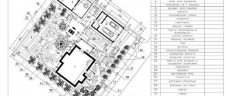
Project and drawing of a two-story cottage created in Autocad
Then you will need to create a project and drawing of the house yourself.
Software selection
Experts identify several construction technologies for building houses:
- stone (use of brick, foam block);
- permanent formwork;
- frame-panel;
- wooden (using beams or logs).
The technologies described above are used for private construction. To create a house project yourself, experts advise using paid or free online programs for designing houses. If possible, you can buy a licensed version of the software. Home design is a branch of architecture and design.
House layout created in AutoCAD
To correctly carry out such a task, a multifunctional special program is used. With its help you can:
- calculate consumables;
- draw a building;
- model a house in 3D.
Creating a house project on a computer is a difficult task. Therefore, in the absence of experience in this field of activity, consultation with specialists will be required. Otherwise, it is recommended to use simple online programs. They are designed for economical construction and the creation of standard house designs. More complex programs are used to create an original idea.
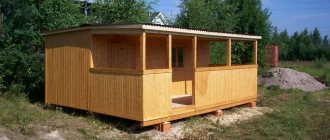
If you want to build a wooden house, then software for designing wooden houses is used. It allows you to create a three-dimensional model of a wooden house based on data on the dimensions of the logs. In this case, the user independently specifies the location of the transverse cuts.
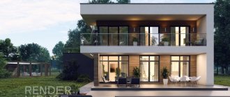
Three-dimensional model of a two-story house made in AutoCAD
In other cases, online 3D modeling programs are used. Such software performs building design in a semi-automatic mode.
Using the given dimensions, the program will independently draw a house plan. If necessary, the user can make his own adjustments. You can draw a house plan in AutoCAD and KOMPAS-3D.
These programs are first downloaded and installed on a PC.
Purpose of materials and textures
The next stage of creating a project is applying textures to the surfaces of the created three-dimensional objects. During construction, all bodies are assigned a default material and texture, which is unacceptable for rendering 3D projects in which each object has its own characteristics.
To apply a texture, launch the Material Browser in the Render Ribbon. The easiest way to apply a texture to a surface is to first select the surface, then in the Material Browser, select the texture you want, right-click on it and select Assign to Selected Objects.
If the AutoCAD library does not have the material or texture you need, you can easily create it using the Material Editor, which is launched by clicking the Create Material button located at the bottom of the Material Browser.
List of software
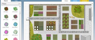
The Arcon program is often used to design houses. It allows you to see the future structure in three dimensions. This program is designed to solve issues related to the preliminary design of a house of any complexity. Arcon is an online software with a clear and simple interface that is used to plan a private country house. If necessary, the user can design each room separately, putting the necessary inscriptions and dimensions on the plan. The finished project can be printed.
Designing a house in the Arcon program
To simplify the process of creating a house plan in Arkona, different textures are provided. The program library consists of more than 1,300 textures and 3,000 interior objects. If necessary, the user can upload his elements in 3ds format. The Arcon program also provides the function of designing stairs to the second floor of various shapes. This software can be used for remodeling premises. Experts include the main tools of such software:
- door and window designer;
- calculation of shadow, lighting, light;
- module for editing or creating 3D elements.
To design a house in three dimensions, you can use the free program FloorPlan3D. With its help, you can also plan the design of each room and make the necessary calculations.
Visualization
After a three-dimensional model of the room has been created, all textures have been applied, cameras and sources have been specified, you can proceed to the final stage of work - visualization.
To configure visualization, use the “Visualization” panel. Using the drop-down list, you need to set the visualization quality (from “Draft” to “High” and “Presentation”) and image resolution.
The visualization process is started by clicking the “Visualization” button and occurs in a separate window.
Rendering speed greatly depends on the size of the model, the quality of the applied textures, the number and variety of light sources, the set quality and the size of the final image. The process of obtaining a finished image can last several hours or even days.
Conclusion
As you can see, creating and visualizing a 3D model in AutoCAD is not at all difficult, you just need to follow a certain sequence of actions: first prepare a high-quality model, then assign materials and textures to its elements, install cameras and light sources, and only at the end perform the visualization of the project itself .
Careful study of each stage is a prerequisite for obtaining the final high-quality result in the form of photorealistic images of your project.
Introduction to AutoCAD
You can draw a future building in AutoCAD. This program provides the ability to view 8 project creation slides, each of which consists of several sub-items. If necessary, the user can view ready-made drawings of a frame house from different sides in 3D mode at any time. The next step is to become familiar with the building design requirements. At this stage it is necessary:
- Determining the main dimensions of the house.
- Layout.
- Construction zone.
- Calculation of consumables.
We draw a house plan in AutoCAD, using transfer tools, segments, copying (mirror), and shifting lines to the required distance. Therefore, it is recommended to first study the software tools.
Autocad program interface
To do this, you can watch video tutorials or experiment on your own.
SGround.ru
Let's look at the first basic concepts and requirements needed for construction drawing - this is necessary before we move on and learn how to create full-fledged drawings.
Approximate outline of the article:
- What you need to know and be able to do in AutoCAD to get started
- Why exactly 2D AutoCAD, and not, for example, the now “fashionable” Autodesk Revit
- Features of creating construction drawings
- The most productive way to draw in AutoCAD
What you need to know and be able to do in AutoCAD to get started
This series of articles will not contain basic elements such as “creating a segment”, “creating a dimension” - there is a lot of information on this topic on the Internet, so if you are completely new to AutoCAD, first read how:
- use frames for selecting objects (frames in AutoCAD are of 2 types, depending on whether it is stretched from left to right or from right to left)
- create segments, including lines of a certain length and direction;
- create polylines, circles, arcs, rectangles, hatching, etc.;
- create dimensions;
- use bindings (angular, to the end point, to intermediate points, etc.);
- move objects using snaps or at certain distances;
- use the commands “Similarity” (Offset), “Crop”/“Extend”, “Scale”, “Mirror reflection”, “Rotate” (including with Reference angle), “Chamfer”, “Stretch”, “Copy” ( including with a base point), etc.
I note that in order to work more effectively in AutoCAD, it is important to understand the relatively complex commands: “Stretch”, “Rotate with Reference Angle” and “Copy with Base Point” , as well as clearly understand how to use the green and blue selection frames.
In addition, you need to learn how to work with blocks in the block editor and during contextual editing - we will also dwell on this in the following articles. And it's important to have a clear understanding of how object snaps work.
Why exactly 2D AutoCAD, and not, for example, the now “fashionable” Autodesk Revit
In short, Autodesk Revit, in my deep conviction, is still very far from being able to be used for real work. While the customer needs drawings prepared in accordance with GOST as the result of the work, Revit will not be able to help us, at least in the coming years...
Despite the fact that quite a few design organizations have decided to switch to Revit, I believe that they are making a serious mistake. Revit is suitable for creating 3D models, visualizing buildings and structures (pictures, architectural sketches), and in this it is not bad.
Revit rendering example
But in Revit, the creation and execution of design and architectural drawings, the creation of specifications, and even the creation of families occurs with terrible agony and “crutches”, which leads to the need to maintain expensive “BIM managers” (2-3 pieces per organization) who are hired for themselves all the agony of debugging crooked Revit and want to receive a salary of no less than 120 tr. per month. In addition, work in Revit is much slower than in 2D AutoCAD, and the accuracy that should seem to be an advantage of Revit does not appear due to the same errors of designers with references and parameters (and by the way, errors there seem to be more difficult to track down).
Perhaps in many years, like AutoCAD (debugged by developers for more than 20 years, but still far from perfect), Revit will also become operational. Well, for now it’s better to forget about it a little - for a design engineer whose goal is to create drawings designed in accordance with GOST, it is not suitable.
There are good 3D modeling programs, for example Tekla Structures, the Model Studio CS software package (Russian development, by the way). But the first, although an excellent program, works only in a very narrow area (drawing of KM and KMD metal structures), and the second is still very little widespread. There are probably other programs - I won’t pretend to know everything.
Based on the above and despite the statements of “revists” and would-be “BIM managers” that 2D AutoCAD is an outdated “drawing board” - 2D AutoCAD is still more than relevant and efficient.
Features of creating construction drawings
The creation and execution of construction drawings is carried out in accordance with the requirements of GOST R 21.1101-2013 “System of design documentation for construction (SPDS). Basic requirements for design and working documentation" and other GOSTs regulating the preparation of drawings in the field of construction.
This means that objects such as callouts (marking, node, multilayer, etc.), level marks, coordination axes, section marks, tables appear in the drawings: corner specifications, room explications, parts lists, consumption sheets, styles and others.
An example of applying callouts, dimensions and cut marks to a drawing
An example of applying element marks, level marks and coordination axes to a drawing
This also means that when drawing, a strictly limited list of image scales, certain rules for constructing images, etc. are used.
The most productive way to draw in AutoCAD
Now let’s look at some of the most important techniques to simplify the designer’s work and speed up the creation of a drawing:
- All drawings must be created in "model space". Despite the great functionality of AutoCAD for working in sheets and with viewports, this is a less productive and more inconvenient way of working than drawing everything, including format frames, in “model space”. Sheets are used in some special cases (when one drawing shows many stages of construction and they are highlighted separately in the sheets, when creating General Plan drawings, etc.).
- It is necessary to use the SPDS GraphiCS application - at the moment this is the most convenient addition to AutoCAD specifically for construction drawing, which makes the work much . It allows you to create convenient interactive callouts of various types, level marks, section marks, etc. in one click; it contains pre-configured tables and formats in accordance with GOST SPDS, coordination axes, break lines and much more. This add-on also contains ready-made images of sections of rolled metal of all types and sizes, bolts, nuts, etc.
- You must use the minimum required number of Layers, dimension and text styles. Assigning layers and styles to objects during the drawing process often takes more time than it's worth - this is something to consider.
- It is necessary to use hotkeys, at least the minimum set: Ctrl+C, Ctrl+Shift+C, Ctrl+V, Ctrl+Shift+V – and further expand it, because their use significantly speeds up work.
- It is necessary to carry out drawings in the minimum required detail. This means that when creating a building plan drawing, you do not need to draw, for example, all layers of sheathing, profiles and screws in gypsum plasterboard partitions.
- Instead of segments, use continuous polylines wherever possible. Also, in all justified cases (when the same image is repeated many times) it is necessary to use blocks.
We will dwell on individual points in more detail in the following lessons.
Completing of the work
To draw a house plan, you will need to draw its axes: horizontal and vertical. Then we draw the lines of the walls using objective snapping. We draw them on 2 sides relative to the entire axis. Then we delete the lines that extend beyond the walls. Using three-dimensional modeling in AutoCAD, you can solve the problem in several ways. Designing a house can be done manually (using 2D primitives) or you can create several interconnected projections from one 3D model.
To build walls use:
- standard primitive “Box” and subsequent union;
- extrusion of a closed contour;
- team "Polytelo".
Experts advise beginners to draw a house plan in AutoCAD using the latter method.
The “Polysolid” command is an analogue of 2D, with which the user can:
- create arc-shaped segments;
- convert flat primitives (circle, rectangle);
- quickly erect partitions.
Installation of cameras and light sources
To obtain high-quality visualization of the model, it is necessary to create and configure light sources. In AutoCAD, you can set point, directional and distant light sources, as well as natural sunlight, to obtain 3D visualization.
To install a light source, run the appropriate command on the “Visualization” ribbon and specify the location of the source. In the properties of the source you can define its name, intensity and color of the glow.
If the task is to visualize a closed room, then to be able to view it “from the inside” it is necessary to create a camera or a whole group of cameras.
To install a camera, run the “Create Camera” command, specify its location and determine the position of the target. In the camera properties you can configure its focal length, field of view and other parameters
To activate the camera, select its name in the “View” panel, in this case you will be able to “look” at the model through the camera lens.