A hydraulic accumulator (expansion membrane tank) serves to maintain pressure in a pressure water supply system, and when used in conjunction with a pressure switch, allows you to create an automatic station based on a submersible or surface pump. The main purpose of the hydraulic accumulator in the system is to maintain and smoothly change the fluid pressure in the system.
Additional functions performed by the hydraulic accumulator are as follows:
- Protection against water hammer (changes in fluid pressure caused by an instantaneous change in its speed)
- Ensuring a minimum supply of water
- Limitation of intermittent pump starts
Thus, it is the hydraulic accumulator that makes it possible to use a pressure switch and automate the water supply process. Without a hydraulic accumulator, the relay cannot work correctly, since an instantaneous change in pressure in the system (at the moment of opening a tap, disconnecting or connecting new consumers, turning a pump on or off, etc.) would cause the relay to constantly operate. And this, in turn, leads to instability of supply, overheating or breakdown of the electric motor, and breakdown of the relay.
Since water is practically incompressible, turning on a pump in a system with a pressure relay, but without a hydraulic accumulator, would cause an instant increase in pressure in the system and the relay would immediately react to this and turn off the pump. On the other hand, when the tap was opened, the pressure would immediately drop and the relay would react and turn on the pump.
Water compressibility coefficient = 5 x 10^10 1/ Pa. Those. An increase in water pressure (the pressure created by the pump) practically does not cause a change in its volume (these are hundredths of a percent). Therefore, the pressure in the system would change at a high speed, which would cause the relay to constantly operate.
It must be clearly understood that the hydraulic accumulator does not create any pressure and does not pump water to the consumer itself - all this is done by the pump. It only maintains the liquid pressure that is created in it by the pump and supplies water at that moment in time while the consumer’s tap is open and the pump is not turned on. For example, the question “What volume of hydraulic accumulator do I need if I have two showers?” not entirely correct. Because when using a shower (one or two), the hydraulic accumulator supplies water only until the pump is turned on, and then only the pump supplies water for the remaining time of use. And it will stop only after all the taps are closed and the pressure in the tank rises to the shutdown pressure.
Sometimes it happens that the pump turns off even while consumers are using water. However, this mode of operation is undesirable (since after a short time the pump will have to turn on again) and indicates that the selection of the pump and/or the settings of the entire system are incorrect (in most such cases it is necessary to change the settings of the pressure switch).
Any hydraulic accumulator is divided by a membrane into two cavities: air and water. By supplying water under pressure into the water cavity of the tank, the membrane expands and compresses the air in the air cavity. Thus, the membrane is balanced by pressure on both sides (P1V1 = P2V2). The pressure will increase until the pump is switched off at the pressure switch setting (pump cut-off pressure). At the moment water flow begins, air presses on the membrane, thereby pushing water out of the accumulator. The water pressure slowly drops and when the pump activation pressure is reached, the relay will close the contacts and the pump will start. This is the schematic diagram of the automatic operation of the pump together with a hydraulic accumulator and a pressure switch.
What should be the air pressure in the air cavity of the accumulator?
The pressure in the air cavity of the hydraulic accumulator should be 10% less than the pump activation pressure.
Moreover, the air pressure needs to be measured only with the tank disconnected from the system (without water pressure). Air pressure must be regularly monitored and, if necessary, brought back to normal; this will significantly extend the life of the membrane. For the same purpose, it is not recommended to make the pressure difference between turning the pump on and off too large. The optimal difference is 1.0-1.5 atm. Larger differences stretch (load) the membrane more, thereby reducing its service life, and moreover, large pressure differences are not comfortable when using water.
It is recommended to install hydraulic accumulators in places not subject to flooding and with low humidity. In this case, the accumulator flange will last much longer. Since the tank does not bear any load, there is no need for additional fastening. The hydraulic accumulator can simply be installed on the floor on standard supports.
When choosing a specific brand of hydraulic accumulator, you should pay attention to the membrane material, the availability of certificates and sanitary and hygienic certificates certifying that the hydraulic accumulator is intended for use in drinking water systems. It’s also a good idea to make sure you have spare membranes and flanges, so that in case of problems you don’t have to buy a completely new tank.
The maximum pressure for which the accumulator is designed should not be less than the maximum possible pressure in the system (for example, if the pressure switch breaks down). This is why most tanks are designed for a pressure of 10 bar.
The question often arises about how much water is in the accumulator?
For example, if the power goes out, how many liters of water can be used?
This value depends on the settings of the pressure switch. As you might guess, the higher the pressure difference between turning the pump on and off, the more water will enter the accumulator, however, this difference must be limited for the reasons stated above.
As an example, we provide a table of the filling capacity of hydraulic accumulators.
| P air, bar | 0,8 | 0,8 | 1,8 | 1,3 | 1,3 | 1,8 | 1,8 | 2,3 | 2,3 | 2,8 | 2,8 | 4,0 |
| P on pump, bar | 1,0 | 1,0 | 2,0 | 1,5 | 1,5 | 2,0 | 2,0 | 2,5 | 2,5 | 3,0 | 4,0 | 5,0 |
| P off pump, bar | 2,0 | 2,5 | 3,0 | 2,5 | 3,0 | 2,5 | 4,0 | 4,0 | 5,0 | 5,0 | 8,0 | 10,0 |
| Total tank volume, l | Water reserve, l | |||||||||||
| 19 | 5,70 | 7,33 | 4,43 | 4,99 | 6,56 | 2,53 | 7,09 | 5,37 | 7,46 | 6,02 | 8,11 | 8,35 |
| 24 | 7,20 | 9,26 | 5,60 | 6,31 | 8,28 | 3,20 | 8,96 | 6,79 | 9,43 | 7,60 | 10,24 | 10,55 |
| 50 | 15,00 | 19,29 | 11,67 | 13,14 | 17,25 | 6,67 | 18,67 | 14,14 | 19,64 | 15,83 | 21,33 | 21,97 |
| 60 | 18,00 | 23,14 | 14,00 | 15,77 | 20,70 | 8,00 | 22,40 | 16,97 | 23,57 | 19,00 | 25,60 | 23,36 |
| 80 | 24,00 | 30,86 | 18,67 | 21,03 | 27,60 | 10,67 | 29,87 | 22,63 | 31,43 | 25,33 | 34,13 | 35,15 |
| 100 | 30,00 | 38,57 | 23,33 | 26,29 | 34,50 | 13,33 | 37,33 | 28,29 | 39,29 | 31,67 | 42,67 | 43,94 |
| 200 | 60,00 | 77,14 | 46,67 | 52,57 | 69,00 | 26,67 | 74,67 | 56,57 | 78,57 | 63,33 | 85,33 | 87,88 |
| 300 | 90,00 | 115,71 | 70,00 | 78,86 | 103,50 | 40,00 | 112,00 | 84,86 | 117,86 | 95,00 | 128,00 | 131,82 |
| 500 | 150,00 | 192,86 | 116,67 | 131,43 | 172,50 | 66,67 | 186,67 | 141,43 | 196,43 | 158,33 | 213,33 | 219,70 |
| 750 | 225,00 | 289,29 | 175,00 | 197,14 | 258,75 | 100,00 | 280,00 | 212,14 | 294,64 | 237,50 | 320,00 | 329,55 |
| 1000 | 300,00 | 385,71 | 233,33 | 262,86 | 345,00 | 133,33 | 373,00 | 282,86 | 392,86 | 316,67 | 426,67 | 439,39 |
According to this table, in a 200 liter hydraulic accumulator with the following pressure switch settings: Pump on - 1.5 bar Pump off - 3.0 bar Air pressure - 1.3 bar
The water supply will be 69 liters, which is approximately a third of the total volume.
In conclusion, a few words about the required volume of the hydraulic accumulator.
V t = K x A max x ((P max +1) x (P min +1)) / (P max – P min) x (P air + 1)
A max - estimated maximum water flow (liter/min) K - coefficient depending on the power of the pump electric motor (see table below) P max - pump switch-off pressure, bar P min - pump switch-on pressure, bar P air. — pressure in the air cavity of the hydraulic accumulator, bar
| Pump power, kW | 0,55-1,5 | 2,2-3,0 | 4,0-5,5 | 7,5-9,0 | ||||||||
| Factor K | 0,25 | 0,375 | 0,625 | 0,875 | ||||||||
We will select the minimum required volume of the hydraulic accumulator for the water supply system based on the Aquarius BTsPE 0.5-50 U pump with the following settings:
P max = 3.0 bar P min = 1.8 bar P air. = 1.6 bar A max = 2.1 m³/h (35 l/min) K = 0.25 (since the pump power is in the range of 0.55–1.5 kW)
V t = 31.41 liter
We select the next closest volume of the hydraulic accumulator - 35 liters.
Note that the tank volume of 24-50 liters is in excellent agreement with other methods for calculating hydraulic accumulators for domestic water supply systems and empirical recommendations of various manufacturers of pumping equipment.
A larger volume should be chosen if there are frequent power outages, but it must be remembered that in any case, water fills approximately a third of the total volume (see the occupancy table above). And of course, the more powerful the pump is installed in the system (relevant for pumps with a power of 1.1 kW and above), the larger the size of the hydraulic accumulator should be preferred, this will reduce the number of repeated short-term starts and extend the service life of the pump motor.
When purchasing large-volume hydraulic accumulators, you must be aware that water must be used regularly, since with prolonged inactivity, its quality begins to deteriorate. After all, using all the water from a hydraulic accumulator with a volume of 24 or 50 liters is much easier and faster than from a 100 or 200 liter one.
Models and prices for hydraulic accumulators can be found in the section “
And one question remained unclear: when to inflate the accumulator with air, before filling with water or after? Logically, it seems that you need to pump up before, but after searching the answer on the Internet, it turned out that some recommend doing this after.
In general, it is correct to pump the accumulator dry until it is filled with water.
To calculate the required pressure in the air part of the accumulator, you can use formulas; if you are lazy, then the air pressure in the accumulator is calculated using a very simple formula, it should be 10% less than the pressure at which the pressure switch turns on the pump. Typical values of the minimum and maximum pressure values at which the pump turns on and off are 1.5 and 3 bar, subtract 10% from 1.5 bar and get 1.35 bar of air we need to pump into the accumulator.
If you don’t like this calculation, you can use a more scientific approach:
Also keep in mind that the hydraulic accumulator requires periodic maintenance. Water always contains a small part of dissolved air, and this air gradually reduces the useful volume of the bulb (rubber membrane) in the accumulator. On large-capacity hydraulic accumulators, as a rule, there are special valves for releasing this air; in small hydraulic accumulators, which are usually equipped with household pumping stations, there are no such valves, and to remove air from the membrane, a simple operation must be performed every couple of months.
1. It is necessary to turn off the power to the pump and drain all the water from the accumulator; it is best, of course, to provide a special tap for this, or use the tap closest to the accumulator.
2. The procedure from point 1 must be done 2-3 times in a row.
And please do not confuse the hydraulic accumulator and the water storage tank, these are different devices, the hydraulic accumulator is designed to reduce the number of pump starts, and as a result increase its service life, as well as to protect against water hammer; in the event of a power outage, the hydraulic accumulator will of course supply water for some time you with water, but I wouldn’t count on much. In case of power outages or water supply breakdowns, a storage tank is needed.
Pressure switch
- an element that controls the operation of a pumping station (for example AQUAJET or AQUAJET-INOX) and which makes it possible to operate it in automatic mode. The pressure switch has several characteristics:
- Turn-on pressure
(
P on
) is the pressure (bar) at which the pumping station is turned on by closing the contacts in the pressure switch. Sometimes the switching pressure is also called “lower” pressure. - Switch-off pressure
(
P off
) is the pressure (bar) at which the pumping station is switched off by opening the contacts in the pressure switch. Sometimes the shutdown pressure is also called “upper” pressure. - Pressure drop
(
ΔP
) is the absolute difference between the cut-out pressure and the cut-in pressure (bar). - The maximum shutdown pressure
is the maximum pressure (bar) at which the pumping station can be turned off.
Any pressure switch has factory settings and, as a rule, they are as follows: Switch-on pressure: 1.5-1.8 bar Switch-off pressure: 2.5-3 bar Maximum switch-off pressure: 5 bar
How it all works:
Let’s say the pumping station is connected (more on this in the article “Preparing the DAB pumping station for operation”), and the entire system is filled with water. After opening any tap (shower, sink, etc.) and starting to draw water, the pressure in the system will begin to drop smoothly (thanks to the membrane hydraulic tank), which is easy to track with a pressure gauge. All this time, water is supplied to the consumer from the hydraulic tank. When the “lower” switching pressure is reached (it can also be monitored by a pressure gauge at the moment the pump is switched on), the contacts inside the pressure switch will close and the pump will start. The rest of the time of water collection, the pump continues to operate, supplying water directly to the consumer. After the water withdrawal is completed (all taps are closed), the pump still continues to work, only now the water is not supplied to the consumer, but is pumped into the hydraulic tank (since it has nowhere else to go) and the pressure gradually increases. When the shutdown pressure is reached (can be easily monitored on the pressure gauge when the pump stops), the contacts inside the pressure switch open and the pump stops. At the next water draw, the cycle repeats. It's quite simple.
But what to do if the factory settings of the pressure switch are not very comfortable? For example:
on the upper floors the pressure drops very noticeably, or the water purification system requires at least 2.5 bar at the inlet, while the pump turns on only at 1.5-1.8 bar.
You can set the pressure switch yourself:
Using a pressure gauge, we record the on and off pressure when the pump is running. Turn off the power to the pump and remove the top cover of the pressure switch (usually by unscrewing one screw). You will see two screws, one larger one is located on the top of the relay, and the second, slightly smaller one, is located below it. The top screw is responsible for the shutdown pressure and, as a rule, next to it there is the letter “P” and an arrow with the signs “+” and “-”. Then we rotate the screw in the desired direction (if the shutdown pressure needs to be raised, then rotate in the direction of the “+” sign, if lowered, then in the direction of the “-” sign). How much to rotate? Make a turn (half a turn, one and a half - as much as you want). After this, we start the pump and see at what pressure it turns off now. We remember, turn off the power to the pump, and rotate the screw further, start the pump again and write down the new value, thus getting closer to the desired value.
The lower screw is responsible for the difference between the cut-off pressure and the cut-in pressure. As a rule, “ΔP” is written next to it and there is an arrow with “+” and “-” signs. Setting the pressure difference is similar to setting the cut-off pressure. There is only one question left: what should it be? The difference between switch-on and switch-off pressure is usually 1.0-1.5 bar. Moreover, the higher the shutdown pressure, the greater this difference can be. For example, with factory settings P on = 1.6 bar, P off = 2.6 bar, the difference is 1 bar, this is exactly the standard value. If we want to change the factory settings and raise P off to 4 bar, then the difference can be made by 1.5 bar, i.e. P on should be set at 2.5 bar. You must understand that the greater this difference, the higher the pressure drop in the system, which is not always comfortable. But at the same time, the pump will turn on less often, and more water will flow from the hydraulic tank before the pump turns on.
This is only true if the pump can provide the required pressure (see pump characteristics). Those. if the pump can only produce 3.5 bar according to its passport (taking into account all types of losses), then setting the pressure switch to turn off 4 bar will not do anything. The pump simply will not be able to provide the required pressure and in this case will work without stopping. And if you still need exactly 4 bar, then you will have to change the pump to a more powerful one.
Settings
Before adjusting the relay, you need to take into account that its values are inextricably linked with the pressure inside the membrane tank. First you need to create the required amount of pressure inside it, and then move on to working with the control in question.
The adjustment is carried out in 3 stages:
- pressure inside HA
- pump start level
- shutdown mark
For optimal operation, it is necessary to adjust the parameters several times experimentally, taking into account the water flow, the height of the pipes and the pressure in them.
Indicators inside the accumulator
It is advisable that the pressure adjustment in the accumulator take into account the following examples and rules:
- for a one-story house, 1 bar is enough, and if the tank is installed in the basement, then add 1 more
- the value must be greater than at the highest point of water intake
- how many atmospheres should be inside the container is determined by the following formula: add 6 to the height of the pipes to the highest point of water intake and divide the result by 10
- if there are many consumption points or the branching of the pipeline is significant, then a little more is added to the resulting figure. How much to add is determined empirically. There is the following rule for this. If the value is too low, then water will not be delivered to the devices. If it is too high, the HA will be constantly empty, the pressure will be too strong, and there will also be a risk of membrane rupture.
In order to increase the pressure in the accumulator, air is pumped up with an ordinary bicycle pump (there is a special spool on the body); to lower it, it is vented. The pneumatic valve for this purpose is located under the decorative trim. The procedure must be done in the absence of water pressure, which requires simply closing the taps.
The value of the indicators is determined by a pressure gauge connected to the spool. The correction is made after the pump has turned off. The pressure difference is created by opening the tap at the nearest point.
Manufacturers standardly set the pressure in the tank to 1,5 – 2,5
bar. Its increase reduces the usable space inside the container and increases the pressure in the system - this must be taken into account when calculating.
Basics of adjusting thresholds
There are two springs with nuts: the larger one is responsible for the values for turning off the pump, the smaller one is for turning it on. The bolts are loosened or tightened, thereby making adjustments.
Setting up the accumulator pressure switch will be of high quality if you follow these rules:
- the average recommended difference between the values for turning the pump on and off is 1 - 1.5 atm
- the pressure inside the HA must be lower than the set value to turn on the pump by 10%. Example: if the activation mark is set to 2.5 bar, and the switch off mark is set to 3.5 bar, then there should be 2.3 bar inside the container
- the hydraulic accumulator and control unit have their own load limits - when purchasing, you need to check whether they coincide with the calculations for the system (pipe height, number of intake points, flow rate)
The mechanism in question controls the maximum and minimum pressure in the tank. It maintains the difference in its values when the station is activated and switched off. The limit of its settings depends on the power and hourly flow rate of the pump.
Factory parameters are indicated in the product data sheet. Usually they are like this:
- limit limits – 1 – 5 atm
- pump operating range – 2.5 atm
- starting point – 1.5 atm
- maximum switch-off level – 5 atm
Preparation and example of setting the required values
Preparation:
- tank is connected
- the control unit is adjusted under pressure, the system is not disconnected from the power supply
- inside the unit the pressure should be 10 - 13% lower than that of the pumping station. That is, approximately 0.6 - 0.9 atm than the mark at which the engine turns on
- all taps are closed
- the set level is checked with a pressure gauge within an hour to make sure there are no leaks
- remove the block housing cover to have access to the nuts and observe the springs
Setting with an example of setting marks of 3.2 atm to turn off and 1.9 atm to turn on (two-story house):
- Start the pump to determine the pressure in the system. It should fill the storage part of the device and increase the pressure.
- They determine at what pressure gauge reading the shutdown will occur (usually no more than 2 atm.) When exceeded, a small spring comes into action, which is clearly visible.
- The motor is stopped above 3.2 - 3.3 atm, this figure is reduced by rotating the nut on the small spring a quarter turn, since it is very sensitive, until the motor turns on.
- They check with a pressure gauge: 3 - 3.2 atm will be enough.
- Turn on the tap to relieve the pressure and so that the HA is freed from the liquid and record the pump activation mark with a pressure gauge, usually 2.5 atm - the lower pressure indicator has been reached.
- To reduce the lower threshold, rotate the large spring bolt counterclockwise. Next, start the pump until the pressure rises to the required level, after which you need to check the pressure with a pressure gauge. An acceptable value is 1.8 - 1.9 and the nut is rotated clockwise.
- Once again, adjust the small spring a little, clarifying the already set thresholds.
The adjustment bolts are very sensitive - turning just 3/4 of a turn can add 1 atm. The pressure of the switched-on pump should be 0.1 - 0.3 atm higher than in an empty storage tank, which will prevent damage to the “bulb” inside it.
The setup process in brief
For a better understanding of how to set up a pressure switch, we will outline the process more clearly:
- pump activation mark (minimum pressure): rotating the large spring bolt clockwise increases the starting mark, counterclockwise decreases it;
- value for shutdown: move the small spring, when tightening - the pressure difference increases, when unscrewing - the actuation mark decreases;
- the result is checked by opening the tap and draining the water, recording the moment the pump is turned on;
- The internal pressure force is adjusted by deflating or pumping air and checking this with a pressure gauge.
Increasing the factory switching parameters (above 1.5 atm) creates a risk of critical load on the hydraulic tank membrane. The operating range of the pump is adjusted taking into account the maximum possible load for the water fittings. The sealing rings of household taps can withstand a maximum of 6 atm.
What should the air pressure be in the air cavity of the hydraulic tank?
Many people don’t think about it, or simply don’t know that they need to keep an eye on this. Unfortunately, yes, it is necessary; the service life of the hydraulic tank membrane, and ultimately the pump, directly depends on this.
We measure the air pressure in the air cavity of the hydraulic tank. We do this only with the hydraulic tank disconnected from the system.
— turn off the power to the pump, open any tap behind the pump and wait until the water comes out of the hydraulic tank.
Or we measure it on an installation that is not yet connected to the water supply system. To do this, remove the decorative cap from the air nipple of the hydraulic tank and connect a regular car pressure gauge to it (to check the pressure in the car tires). Let's remember this pressure. (As a rule, on small hydraulic tanks with a capacity of up to 50 liters, this pressure will be 1.5 bar). Now the most important rule : the air pressure in the hydraulic tank should be less than the pump activation pressure by about 10%
. Those. if the pump activation pressure is 1.6 bar, then the air pressure should be 1.4-1.5 bar. In most cases, these are the factory settings mentioned above. Those. By purchasing a ready-made pumping station, you already have a fully configured system. But once you have made changes to the factory settings of the pressure switch, you must always change the air pressure in the hydraulic tank. For example, if you set P on = 2.5 bar, P off = 3.5 bar, then it is necessary to raise the air pressure to a value of 2.2-2.3 bar.
By the way, even if you haven’t changed anything in the factory settings, you need to regularly monitor the air pressure, or at least check it once a year at the beginning of the summer season. It is important that this pressure be constant, but if it has dropped a little over the winter, it can always be raised with a regular car pump to the required level.
All these simple operations will not take much time; it is enough to pay attention to them once a year, especially since everything will pay off in the long and uninterrupted operation of the entire water supply system as a whole.
2007 website Setting the pressure switch and adjusting the air pressure in the accumulator.
To prevent the pump from turning on every time a faucet is opened in the house, a hydraulic accumulator is installed in the system. It contains a certain volume of water, sufficient for a small flow rate. This allows you to practically get rid of short-term pump starts. Installing a hydraulic accumulator is not difficult, but you will need a few more devices - at least a pressure switch, and it is also desirable to have a pressure gauge and an air vent.
Recommendations for use
After the accumulator is installed, it must be properly maintained. About once a month you should check the pressure switch settings and adjust them if necessary. In addition, you need to check the condition of the housing, the integrity of the membrane and the tightness of the connections.
The most common failure in hydraulic tanks is diaphragm rupture. Constant cycles of tension and compression eventually lead to damage to this element. Sudden changes in pressure gauge readings usually indicate that the membrane has ruptured and water is entering the “air” compartment of the accumulator.
To make sure there is a breakdown, you just need to bleed all the air from the device. If water follows it from the nipple, then the membrane definitely needs to be replaced.
Fortunately, these repairs are relatively easy to make. To do this you need:
- Disconnect the hydraulic tank from the water supply and power supply.
- Unscrew the bolts that hold the neck of the device.
- Remove the damaged membrane.
- Install a new membrane.
- Reassemble the device in reverse order.
- Install and connect the hydraulic tank.
Upon completion of the repair, the pressure settings in the tank and pressure switch should be checked and adjusted. The connecting bolts must be tightened evenly to prevent the new membrane from warping and to prevent its edge from sliding inside the hydraulic tank housing.
Replacing the accumulator membrane is relatively easy, but you need to make sure that the new membrane is the same as the old one
To do this, install the bolts in the sockets, and then alternately make literally a couple of turns of the first bolt, move on to the next, etc. Then the membrane will be pressed against the body equally along the entire circumference. A common mistake made by beginners in repairing a hydraulic accumulator is the incorrect use of sealing agents.
The installation site of the membrane does not need to be treated with a sealant; on the contrary, the presence of such substances can damage it. The new membrane must be exactly the same as the old one both in volume and configuration. It is better to first disassemble the hydraulic accumulator, and then, armed with a damaged membrane as a sample, go to the store for a new element.
Functions, purpose, types
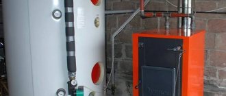
Installation location - in a pit or in a house
In the water supply system of a private house without a hydraulic accumulator, the pump turns on whenever water flows somewhere. These frequent starts lead to wear and tear on the equipment. And not only the pump, but the entire system as a whole. After all, every time there is an abrupt increase in pressure, and this is a water hammer. To reduce the number of pump starts and smooth out water hammer, a hydraulic accumulator is used. The same device is called an expansion or membrane tank, a hydraulic tank.
Purpose
We found out one of the functions of hydraulic accumulators - to smooth out water hammer. But there are others:
It is not surprising that most private water supply systems have this device - there are many advantages from its use.
Kinds
The hydraulic accumulator is a tank made of sheet metal divided into two parts by an elastic membrane. There are two types of membrane - diaphragm and balloon (bulb). The diaphragm is attached across the tank, a pear-shaped cylinder is secured at the inlet around the inlet pipe.
According to their purpose, they are of three types:
- for cold water;
- for hot water;
- for heating systems.
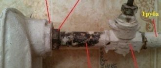
Hydraulic tanks for heating are painted red, tanks for water supply are painted blue. Expansion tanks for heating are usually smaller in size and lower in price. This is due to the membrane material - for water supply it must be neutral, because the water in the pipeline is potable.
Depending on the type of arrangement, hydraulic accumulators can be horizontal or vertical. Vertical ones are equipped with legs; some models have plates for hanging on the wall. It is the elongated upward models that are most often used when independently creating water supply systems for a private home - they take up less space. The connection of a hydraulic accumulator of this type is standard - through a 1-inch outlet.
Horizontal models are usually equipped with pumping stations with surface-type pumps. Then the pump is placed on top of the tank. It turns out compact.
Principle of operation
Radial membranes (in the form of a plate) are used mainly in gyroaccumulators for heating systems. For water supply, a rubber bulb is usually installed inside. How does such a system work? As long as there is only air inside, the pressure inside is standard - the one that was set at the factory (1.5 atm) or that you set yourself. The pump turns on, begins to pump water into the tank, and the pear begins to increase in size. Water gradually fills an increasingly larger volume, increasingly compressing the air that is located between the wall of the tank and the membrane. When a certain pressure is reached (usually for one-story houses it is 2.8 - 3 atm), the pump is turned off, and the pressure in the system stabilizes. When you open a tap or other water flow, it comes from the accumulator. It flows until the pressure in the tank drops below a certain level (usually about 1.6-1.8 atm). After which the pump turns on, the cycle repeats again.
If the flow rate is large and constant - you are filling a bathtub, for example - the pump pumps water in transit, without pumping it into the tank. The tank begins to fill after all the taps are closed.
A water pressure switch is responsible for turning the pump on and off at a certain pressure. In most hydraulic accumulator piping schemes, this device is present - such a system operates in optimal mode. We’ll look at connecting the hydraulic accumulator a little lower, but for now let’s talk about the tank itself and its parameters.
Large tanks
The internal structure of hydraulic accumulators with a volume of 100 liters and above is slightly different. The pear is different - it is attached to the body both at the top and bottom. With this structure, it becomes possible to fight the air that is present in the water. To do this, there is an outlet in the upper part into which you can connect a valve for automatic air release.
Horizontal or vertical
Depending on the installation method, hydraulic accumulators can be vertical or horizontal. Which hydraulic accumulator is preferable? It is necessary to find out how the device removes the air collected inside the membrane (“pear”). The fact is that in any water supply system there is air dissolved in the water. Over time, it is released from the water and, accumulating, forms air plugs at different points in the system. To remove them, large-volume hydraulic accumulators (? 100 liters) are provided with a fitting with a valve through which the air accumulated in the system can be released from time to time. In vertical type hydraulic accumulators (from 100 l), all air is collected in the upper part of the unit and is easily removed using such a valve. In horizontal hydraulic accumulators, air is removed using an additional section of piping consisting of a ball valve, air outlet nipple and drain. Small volume hydraulic accumulators do not have such a valve. Removal of collected air is possible only when the tank is completely emptied. Typically, horizontal hydraulic accumulators are chosen for installing external pumps on them, and vertical ones are chosen for small spaces and when working with submersible pumps. Return to content
How to choose tank volume
You can choose the tank volume arbitrarily. There are no requirements or restrictions. The larger the volume of the tank, the greater the supply of water you will have in case of a shutdown and the less often the pump will turn on.
When choosing a volume, it is worth remembering that the volume that appears in the passport is the size of the entire container. There will be almost half as much water in it. The second thing to keep in mind is the overall dimensions of the container. A 100 liter tank is a decent-sized barrel - about 850 mm high and 450 mm in diameter. You will need to find a place somewhere for it and the harness. Somewhere - this is in the room where the pipe from the pump comes. This is where all the equipment is usually installed.
If you need at least some guidelines to select the volume of a hydraulic accumulator, calculate the average flow rate from each water intake point (there are special tables or you can look at the data sheet for household appliances). Sum up all this data. Get the possible consumption if all consumers work simultaneously. Then figure out how many and which devices can work at the same time, calculate how much water will be consumed in a minute in this case. Most likely by this time you will have already come to some decision.
To make it a little easier, let’s say that the hydraulic tank volume of 25 liters is enough to meet the needs of two people. It will ensure the normal functioning of a very small system: a faucet, a sink and a small one. If you have other household appliances, the capacity must be increased. The good news is that if you decide that the current tank is not enough for you, you can always install an additional one.
What does the pumping station consist of?
An important element for the normal functioning of any pumping station is pressure. Before you find out what reasons exist that affect pressure, it is worth understanding what elements the device consists of:
- Pump.
- Hydraulic accumulator.
- Pressure switch.
- Pressure gauge.
What should be the pressure in the accumulator?
One part of the accumulator contains compressed air, and water is pumped into the second. The air in the tank is under pressure - factory settings - 1.5 atm. This pressure does not depend on the volume - it is the same on a tank with a capacity of 24 liters and 150 liters. The maximum permissible maximum pressure may be more or less, but it does not depend on the volume, but on the membrane and is indicated in the technical specifications.
Preliminary check and pressure correction
Before connecting the accumulator to the system, it is advisable to check the pressure in it. The settings of the pressure switch depend on this indicator, and during transportation and storage the pressure could drop, so monitoring is very desirable. You can control the pressure in the hover tank using a pressure gauge connected to a special input in the upper part of the tank (capacity of 100 liters or more) or installed in its lower part as one of the piping parts. Temporarily, for control, you can connect a car pressure gauge. Its error is usually small and it is convenient to work with. If this is not the case, you can use the standard one for water pipes, but they are usually not very accurate.
If necessary, the pressure in the accumulator can be increased or decreased. There is a nipple at the top of the tank for this purpose. A car or bicycle pump is connected through the nipple and the pressure is increased if necessary. If it needs to be vented, the nipple valve is bent with some thin object, releasing the air.
What air pressure should be
So should the pressure in the accumulator be the same? For normal operation of household appliances, a pressure of 1.4-2.8 atm is required. To prevent the tank membrane from tearing, the pressure in the system should be slightly higher than the pressure of the tank - by 0.1-0.2 atm. If the pressure in the tank is 1.5 atm, then the pressure in the system should not be lower than 1.6 atm. This value is set on the water pressure switch, which works in tandem with the hydraulic accumulator. These are the optimal settings for a small one-story house.
If the house is two-story, you will have to increase the pressure. There is a formula for calculating the pressure in the hydraulic tank:
Vatm.=(Hmax+6)/10
Where Hmax is the height of the highest point of water intake. Most often this is a shower. You measure (calculate) at what height relative to the hydraulic accumulator its watering can is located, substitute it into the formula, and get the pressure that should be in the tank.
If the house has a jacuzzi, everything is more complicated. You will have to select it empirically - changing the relay settings and observing the operation of water points and household appliances. But at the same time, the operating pressure should not be greater than the maximum permissible for other household appliances and plumbing fixtures (indicated in the technical specifications).
What is a hydraulic accumulator
A hydraulic tank (or hydraulic accumulator) is a water container with a rubber elastic membrane (resembling a pear) located inside the container and having a sealed connection to the metal body of the tank. This connection is made using a flange with a threaded connection to connect the device to the water supply. The cavity between the membrane and the metal body of the hydraulic tank is filled with compressed air, usually the pressure is 1.5-2 bar. Hydraulic accumulators are used to maintain constant pressure and create a water reserve in domestic or industrial conditions. It is this unit that provides the required pressure in the system when the pump is turned off.
Fig.1.
Hydraulic accumulator structure 1 – metal body; 2 – rubber membrane; 3 – flange with valve (passes air); 4 – nipple for pumping air into free space; 5 – cavity for compressed air; 6 – supports; 7 – platform for the pump. More details about the design of the hydraulic tank in the video: Return to content
How to choose
The main working body of the hydraulic tank is the membrane. Its service life depends on the quality of the material. The best membranes today are made from isobutated rubber (also called food grade). The body material only matters in membrane-type tanks. In those in which a “pear” is installed, water comes into contact only with rubber and the material of the body does not matter.
The flange should be made of thick galvanized steel, but better - stainless steel
What's really important about bulb tanks is the flange. It is usually made of galvanized metal. In this case, the thickness of the metal is important. If it is only 1 mm, after about a year and a half of operation, a hole will appear in the metal of the flange, the tank will lose its tightness and the system will stop working. Moreover, the warranty is only one year, although the stated service life is 10-15 years. The flange usually deteriorates after the warranty period expires. There is no way to weld it - the metal is very thin. You have to look for a new flange at service centers or buy a new tank.
So, if you want the accumulator to last a long time, look for a flange made of thick galvanized or thin, but made of stainless steel.
Operating principle of the unit
The key task of the device is to provide the required pressure when your pump is off.
Let's take a closer look at the features of the work so that, if necessary, we can carry out minor repairs or adjustments ourselves.
When liquid enters the hydraulic tank, the dimensions of the membrane increase. This means that the entire volume of air present there is systematically reduced, at the same time increasing the pressure in the system.
As soon as the planned pressure level is reached, the pump is activated and turns off.
At the same time, the pressure in the system decreases depending on how much water has already been used. Only when it drops to a predetermined mark will the contacts touch and the device begin working again. Take note: be sure to check, at least once every 10-12 months, the air pressure in the accumulator when there is no water in it. If the pressure in the system is below the established norm, it must be raised. The most common car pump will come to the rescue.
Connecting the accumulator to the system
Typically, the water supply system of a private home consists of:
This scheme may also include a pressure gauge for operational pressure control, but this device is not necessary. It can be connected periodically to carry out test measurements.
With or without five-pin fitting
If the pump is of a surface type, the hydraulic accumulator is usually placed next to it. In this case, the check valve is installed on the suction pipeline, and all other devices are installed in one bundle. They are usually connected using a five-pin fitting.
It has terminals with different diameters, just for the devices used for tying the hydraulic accumulator. That’s why the system is most often assembled on its basis. But this element is not at all necessary and everything can be connected using ordinary fittings and pieces of pipe, but this is a more labor-intensive task, and there will be more connections.
How to connect a hydraulic accumulator to a well - diagram without a five-pin fitting
With one inch outlet, the fitting is screwed onto the tank - the pipe is located at the bottom. A pressure switch and pressure gauge are connected to the 1/4 inch outlets. The remaining free inch terminals are connected to the pipe from the pump and wiring to consumers. That's all for connecting the gyroaccumulator to the pump. If you are assembling a water supply circuit with a surface pump, you can use a flexible hose in a metal winding (with inch fittings) - it is easier to work with.
A visual diagram of connecting the pump and accumulator - use hoses or pipes where necessary
As usual, there are several options, the choice is yours.
The hydraulic accumulator is connected to the submersible pump in the same way. The whole difference is where the pump is installed and where the power is supplied, but this has nothing to do with the installation of the accumulator. It is placed in the place where the pipes from the pump enter. Connection is one to one (see diagram).
How to install two hydraulic tanks on one pump
When operating the system, sometimes owners come to the conclusion that the available volume of the accumulator is not enough for them. In this case, you can install a second (third, fourth, etc.) hydraulic tank of any volume in parallel.
There is no need to reconfigure the system; the relay will monitor the pressure in the tank on which it is installed, and the viability of such a system is much higher. After all, if the first accumulator is damaged, the second one will work. There is another positive point - two tanks of 50 liters each cost less than one of 100. The point is that the technology for producing large-sized containers is more complex. So it is also more economical.
How to connect a second accumulator to the system? Screw a tee onto the input of the first one, connect the input from the pump (five-pin fitting) to one free output, and connect the second container to the remaining free one. All. You can test the circuit.
Installation
Often the HA kit is sold disassembled, and the control unit must be installed yourself.
Connecting the pressure switch to the hydraulic accumulator looks like this in stages:
- The station is disconnected from the network. If water has already been pumped into the storage tank, it is drained.
- The device is fixed permanently. It is screwed onto the 5-pin fitting of the unit or onto the outlet pipe and must be firmly fixed.
- The wiring diagram is normal: there are contacts for the network, pump, and grounding. The cables are passed through holes on the housing and connected to contact blocks with terminals.
Electrical connection to the pump