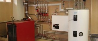
Autonomous heating allows you not to depend on established consumption standards, the pricing policy of heat suppliers and their mood. This makes it possible to independently control the heating process and maintain the most comfortable temperature in the house, while saving resources.
And if you wire your heating boiler with your own hands, then it will last longer and will take up less financial resources, isn’t it? But have you never engaged in tying, and the word itself seems incomprehensible to you at first glance?
Don’t be intimidated by the abundance of pipes, devices and technological steps - after reading the article, you will be up to the task. Here we consider piping schemes for floor and wall types of heating equipment, select illustrative photos and recommendations from specialists for piping at home.
What is boiler piping with polypropylene
Piping is the connection into a single functional complex of heating equipment, equipment systems and hot water supply, ensuring the transfer of hot water to heating devices and water points. A well-executed scheme allows you to evenly distribute heat flows to consumers and ensure reliable operation of all equipment, protecting it from overheating and the possibility of creating an emergency. Before installing heating and pumping equipment, they are calculated; only in this case will the circuit work correctly and efficiently, with operating parameters and efficiency.
You need to understand that there are no ready-made standard options for heating networks; only an individual project can be effective. However, to perform it, a certain standard set of standard equipment is used. A huge advantage of using polypropylene pipelines (PPR) is the unlimited possibilities for creating contours of any complexity. Although specialists should not abuse this, since the complexity complicates installation work and, ultimately, reduces the efficiency of the thermal power plant.
Gas boiler piping
To tie the boiler with polypropylene, you can use both welding technology and the use of fittings. The second option is less popular, since even with small “water hammer” at the installation points, leaks can occur. And although PPR can easily withstand heating fluids from temperatures up to 95 C, there are temperature restrictions that are taken into account when tying the boiler.
The connection of gas fuel to the boiler unit is rigid; SNIiP requires the use of only steel pipelines using a paronite gasket through a steel pipe or “American”.
The pipeline section at the inlet/outlet of the boiler unit up to 1 m is made of steel.
Pipe PN 10
Filters
Mud filters are essential elements of modern heating systems. When installing mud filters, it is important to take into account the rules for their installation, since it is during installation that mistakes are often made. It is also important to remember to clean them from time to time. Sometimes it is enough to install one dirt filter into a closed heating system. It is installed on the section of the main line through which all the coolant passes. Such a place could be, for example, the area in front of the main circulation pump.
Basic rules for installing mud filters:
- It is preferable to install the filter on horizontal sections of the pipeline.
- When installing the filter, it is important to ensure that the direction of movement of the coolant coincides with the marks marked on the body of the device.
- The tap branch, equipped with a screen, nut (or drain cock), should be located at the bottom.
- The dirt filter must be installed in a place that is easily accessible for maintenance.
- Shut-off valves (half-turn valves) should be installed at the inlet to the filter, as well as at the outlet.
Types and characteristics of pipe products for heating systems
Polypropylene pipelines are divided into 4 categories:
- PN 10 - pipes with a thin wall, for low pressure media of no more than 1 atm and T up to 45 C, are practically not used in boiler heating systems, except in sewer low-temperature gravity lines or low-temperature “warm floor” designs.
- PN 16 is a slightly better quality, T up to 60C, and pressure -1.6 atm, but still the material is not suitable for a boiler unit with a medium output of up to 95C.
- PN 20 - has technical characteristics T up to 80 C, and a medium pressure up to 20 atm, can be used in hot water supply schemes or low-temperature heating of small one-story buildings.
- PN 25 - with an ambient temperature of up to 95 C and a pressure of up to 25 atm are acceptable for use in almost any heating system, except for those operating on steam and condensate.
In addition to marking, it is necessary to take into account the coefficient of thermal expansion of pipes, since pipes elongate very much when heated, without taking these properties into account, the new installed system will be deformed upon first start-up, with the formation of numerous leaks. The problem is solved in two ways - by installing compensation loops that reduce elongation and the use of pipes with a reinforcing layer. This option is implemented in PN 25 pipes.
Pipes PN 25, glass fiber reinforced
The foil layer does not come into contact with water, and therefore is not affected by corrosion processes, while reducing the coefficient of thermal expansion by almost half.
There is an even more effective option, PN 25, although it is a little more expensive, with a fiberglass reinforcing layer that reduces all thermal expansion to almost nothing.
Balancing according to design calculations
The easiest way is to balance the system using the data specified in the heating project. The essence of balancing, regardless of the chosen method, comes down to setting the required coolant flow in various parts of the system. The flow is regulated using balancing valves or thermostatic valves with presetting.
The balancing valve has its own gradation. In this case, the different positions of the control valve correspond to a certain volume of coolant that is capable of passing through the device per unit time at a given pressure.
If you have a project for a heating system, you can properly balance it quite simply: by setting the coolant flow rate in accordance with existing calculations.
Evgeniy Kruchinin
But it is important to take into account the fact that often design calculations differ from the actual parameters of the heating system. For example, the hydraulic resistance of a heating circuit can be easily changed by adding or removing an element from the system. But, in general, a good and correct project is a rarity for private houses.
Therefore, even if there is a project, the balancing methods presented below do not lose their relevance.
Options for piping boiler equipment
The source of all heat supply systems is the boiler. It heats the supply coolant usually to T 95 C in the heating system and to T 65 C in the hot water supply, using gaseous, liquid or solid fuel for combustion. The boiler is a dangerous piece of equipment, especially when operating on gas fuel. Its efficient and safe operation can only be ensured by proper harnessing. Particular attention is paid to solid-state heat supply sources that do not have automation systems. Their correct piping will not only create a boiler safety system, but will also allow achieving efficiency at the level of a modern gas unit. Tying a heating boiler with polypropylene, project diagrams, depend on the design of the boiler and the type of network.
With forced circulation
This option for moving water along the boiler circuit is more preferable, especially for heating multi-level buildings of a huge area, where it is necessary to overcome large hydraulic resistance in the network. This is a more modern heating supply scheme, since it allows you to fully automate the heating process, including achieving different temperature conditions in the room.
The only drawback of this type of heating is its energy dependence on the electrical network, without which pumps, smoke exhausters and the control unit will not be able to function. In the traditional version of the harness, balancing of auxiliary equipment, safety automation and regulation is performed. Polypropylene piping of a double-circuit boiler is carried out separately for the heating and hot water circuits.
There are simplified installation schemes using the primary-secondary ring method, which reduces the number of devices, but each ring will need to be equipped with an autonomous pump. A floor-standing double-circuit boiler operating on a system of several rings with a power of up to 50.0 kW is equipped with collectors, called combs, which ensure a uniform supply of heat flows.
With natural circulation
Gravity boilers are considered the simplest to make the piping yourself. A characteristic feature is the absence of a pump that ensures the movement of the medium through the heating circuit. The movement of the medium to the heating devices and its return to the boiler unit for a repeated heating cycle is accomplished thanks to the physical laws of movement of media of different temperatures. A similar piping scheme is well applicable for heating small garden houses; it can be done by almost anyone who can hold a tool in their hands.
To do this you will need:
- Boiler;
- radiators made of cast iron, steel, bimetallic or aluminum;
- hydraulic expansion tank with membrane;
- PPR polypropylene pipes;
- bypass line made of PPR, to turn off heating appliances.
Advantages of piping gravity boilers:
- Quick, simple assembly of the heating circuit;
- small number of auxiliary devices and fittings;
- non-volatile operation of the circuit;
- budget price for equipment configuration and installation;
- the ability to carry out repairs yourself.
The disadvantages include the accuracy of calculating the diameter of the pipes and ensuring their slopes when it is necessary to connect the circuit with natural circulation. The diameters are large, which does not add design to the premises; in addition, the system is configured for maximum performance and is practically not adjustable. However, when the owner gets tired of all this, he can easily install an energy-efficient, small-sized pump into the circuit.
Electric and diesel heat generators
Connecting a diesel fuel boiler to the radiator system is identical to piping gas-using installations. Reason: a diesel unit operates on a similar principle - an electronically controlled burner heats the heat exchanger with a flame, maintaining the set coolant temperature.
Clarification. The recommendation does not apply to heaters equipped with a homemade burner device that burns diesel and waste oil, for example, a Babington flare burner. An individual approach is needed here.
Electric boilers, in which the water is heated by heating elements, an induction core, or through the electrolysis of salts, are also connected directly to the heating. Automation located in an electrical cabinet connected to the network according to the electrical diagram provided is responsible for maintaining temperature and safety. Other connection options are shown in a separate publication on the installation of electric heating boilers.
Wall-mounted mini-boiler rooms equipped with tubular heaters are intended only for closed heating systems. To work with gravity wiring, you will need an electrode or induction unit, which is tied according to the standard scheme:
If you look at it, there is no need for a bypass here - the boiler will not work without electricity either
Criteria for choosing a wiring diagram
They will depend on the type of fuel burned, the total heating area of the object and the state of its thermal insulation, the boiler model and its location.
Basically, one-, two-pipe or manifold installation schemes are used. And if the first two are used for units with natural and forced circulation, then the latter method is workable exclusively in a pump circuit for transporting coolant.
The single-pipe version connects one looped line and the sequential inclusion of heating devices in it. In a two-pipe system, there are 2 independent supply/return pipes from the boiler unit, to which heating devices are connected at the supply level.
With collector piping, one or several collectors are installed, and an independent pipe is laid to each heating device. It also allows you to turn on a “warm floor” made of polypropylene pipelines.
Despite the fact that the collector scheme leads to a decent increase in the cost of the project, but in terms of regulating the heat supply process, it is the most advanced. Modern heating circuits in EU countries operate exclusively using this option. Despite the fact that more complex calculations will be required at the design stage, and the assembly uses a larger volume of PPR pipes, nevertheless, the created system will allow for fine-tuning on a room-by-room basis.
The criteria for choosing an option will depend on the design of the boiler unit:
- Most manufacturing plants require the first meter of pipe to be made of steel, especially for solid fuel boilers.
- Installation of polypropylene pipes for a unit running on gas or stove fuel is carried out using a hydraulic arrow and a manifold.
- Often gas boilers have pumps built into the design of the device.
Piping diagram for a double-circuit gas boiler
Temperature balancing
To balance the system by temperature, we will need the already familiar balancing valves (or thermal heads with presetting) and an electronic thermometer for non-contact measurement of surface temperature.
Balancing begins with the balancing valves on the last and penultimate radiator being fully opened. The coolant flow rate on the first, as well as on subsequent radiators from the boiler, is set to minimum values (with an increase in flow rate as the radiators move away from the boiler).
For example, if there are 8 radiators installed in the system, and the balancing valve screw is adjusted within 4.5 turns, then the first radiator from the boiler is first completely closed, then its balancing valve is unscrewed by 1.5 turns. The regulator of the second radiator is unscrewed by 2 turns, the third by 2.5, and so on. The coolant flow on the last and penultimate radiator in most cases remains maximum. If possible, adjustments are made only on those radiators that are closest to the boiler (the distance is measured from the beginning of the supply line).
It is not recommended to unscrew the regulator less than 1.5 turns. After all, if you turn down the throttle opening of the valve too much, the device will quickly become clogged with scale or other debris.
Fine adjustments are made according to the readings of the thermometer. The main goal of balancing in this case is to achieve approximately the same temperature difference at the inlet and outlet of each radiator.
If the temperature difference at the inlet and outlet of a single radiator reaches 10ºС, it is not recommended to close its balancing valve even more.
And one more thing: noise in the radiator during operation of the heating system indicates that the coolant flow should be reduced.
Nuances and piping options for different types of boilers
General recommendations from experienced professionals:
- The installation scheme is selected individually.
- The boiler is installed in accordance with SNIiP rules below the level of heating devices.
- Before lining with polypropylene, the floor-standing boiler is installed on a metal or concrete base.
- Forced ventilation and emergency lighting systems are recommended for all unit options.
- A coaxial chimney is included in the piping of a device operating on gas fuel, which is sealed at all joints during installation.
- After completing the piping of the boiler unit and chimney, proceed to installing a safety system in the following order: medium pressure devices (pressure gauges), protective devices and then an automatic air vent.
- The manifold circuit is made of a 1.25-inch PPR pipeline; protective devices, a circulation pump, a hydraulic arrow and an air vent are installed according to the movement of the medium.
- To supply the heating coolant to the heating devices, 3 branches of a 1.0-inch PPR pipe are removed from the comb, and the rest are closed with plugs.
- Connect heating and return devices.
- In a combined heating system, the underfloor heating circuit is equipped with an independent pump, while the expansion tank is installed between the hydraulic valve and the boiler unit.
- The piping of the boiler unit is completed by installing a drain valve; it is also used to fill the circuit, but it is better if these are two independent valves. The installation point depends on the chosen system, but there are general conditions - the drain valve is installed at the lowest point, which is especially important if you plan to mothball the system in winter so that there is no water left in it.
Gas equipment
The piping of such equipment with polypropylene pipes is carried out with an independent circuit and a circuit pump that creates operating pressure in a small section of the network from the source to the distributor.
It is allowed to tie a gas unit with such pipes without steel pipes, since the heating temperature at the supply does not exceed 80 C.
In a gas-powered unit with a cast-iron boiler, a heat accumulator is installed, which helps balance the hydraulic regime and prevents sudden temperature changes that affect fragile cast-iron heating surfaces. When piping 2-circuit boilers, it is additionally necessary to place fine and coarse water filters.
Electric heater
Tying an electric boiler with polypropylene is quite acceptable. The boiler has the highest rating for a protective system that prevents the water in the unit from boiling, with subsequent formation of steam and pipe rupture. The heating process stops when the power supply to the electric heating elements is turned off.
In addition, the system has built-in hydraulic accumulators and devices for relieving excess pressure of the environment, which can form during a sudden power outage and stopping the pump for pumping hot water to heating devices and water collection points.
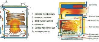
Solid fuel boiler piping
Solid fuel models
This is the most problematic unit for piping plastic pipes. For it, the installation of a protective meter pipe at the inlet/outlet of the medium is mandatory in order to protect them from overheating. For systems with pump circulation, an additional backup power supply device will be required to continue cooling the boiler in the event of an emergency shutdown of the main source of electricity. In addition, a small gravity circuit is made with a small number of connected batteries to cool the boiler heating surfaces until all the fuel burns out.
According to the requirements of fire safety rules, the solid fuel boiler is covered with a protective casing, which significantly reduces heat loss from the walls of the combustion chamber to the boiler room and, consequently, the negative impact on PPR pipes
A small reminder for the installation of plastic pipes - the quality will be determined not only by the installation work, but also by the selected range of pipes. You should purchase all main and auxiliary boiler room equipment only certified from reputable suppliers. Polymer pipes do not require insulation work or painting, scale and corrosion do not form on them, and they are characterized by high noise insulation. The cost of the material is lower, and the pipes are lighter than those made of metal, so installation can be done by yourself.
Pumping and mixing unit
It is possible to construct a heating system according to a combined scheme in a private house using a pumping and mixing unit. The design with it is the most effective, but will be more expensive compared to using a 3-way valve, although the operating principle is the same.
Cooled water from the return pipe dilutes the hot coolant, and the presence of balancing taps allows this to be done in the required proportions.
This unit comes in different configurations. It depends on the purpose and cost of the equipment. The standard device includes:
- thermostatic valve;
- immersion temperature sensor;
- balancing valve with fixing spring valve;
- circulation pump;
- immersion thermometer;
- threaded sleeve;
- bypass and shut-off valve;
- drain and ball valve;
- air vent;
- bypass bypass.
Electrical connection
The power supply circuits are the same for all electric boilers, the only difference is the number of phases. Devices with a power of up to 12 kW are connected to a single-phase 220 V network, more than 12 kW - to a three-phase (380 V). What you will need for installation:
- power cable with copper conductors;
- differential circuit breaker or combination of RCD + conventional circuit breaker;
- ground loop.
A VVG cable of any type is used as a power line; the number of cores depends on the number of phases - 3 or 5. Select the cross-section of the current-carrying part according to the power of the heat generator, usually this parameter is indicated in the product’s operating instructions. To simplify the task, we present the data for different boilers in the form of a table.
The rating of the differential circuit breaker also depends on the power consumption of the heater; the operating current is 30 mA. For example, to protect the power line of a 3 kW (220 volt) unit, you will need a device rated at 16 A; for a power of 16 kW (380 V), you need a 32 A difavtomat. The exact ratings are indicated in the product data sheet.
To independently connect a wall-mounted electric mini-boiler room, you need to remove the front panel, run the power cable inside and connect the wires of the corresponding colors to the terminal block contacts. As a rule, the neutral wire is indicated in blue, grounding in yellow-green. The control box of the induction and electrode boiler is connected in the same way.
Electrical connections between the control cabinet and the heating block of an electrode or induction boiler are made according to the individual diagram presented in the instructions. As an example, we give a connection diagram for the popular Galan electric boiler.
Automation diagram for single-phase 220 V network
The temperature of the coolant here is monitored by overhead sensors installed on the metal sections of the supply and return pipelines. The devices are connected in series with the contacts of the thermal relay that controls the magnetic starter. When the upper temperature threshold is reached, the circuit breaks and the starter turns off the heating.
Connection diagram for connecting the boiler to a three-phase 380 V network
Features of installation of PPR pipelines
When piping a boiler, polypropylene pipes and fittings are connected mainly by cold or hot welding; when connecting to metal pipelines, threaded connections are used. Screwing on is much more convenient, but because of them, assembling the system will cost significantly more.
True, if you want to connect a polypropylene pipeline to a metal counterpart, you cannot do without threaded fittings.
An extensive line of fittings is produced to form linear and nodal connections of polypropylene pipes
“Hot” welding is done with a special apparatus (soldering iron, “iron”). The pipes are heated using a suitable nozzle to a melting temperature of 260 degrees, and then the parts with softened edges are pressed against each other. The result is a reliable and monolithic connection.
Before welding, the foil of reinforced pipes must be cleaned. Otherwise, it will interfere with the connection of polymer products, making the seam fragile. With fiberglass, these unnecessary steps will not be required. It melts easily along with the plastic.
PPR soldering technology is extremely simple, all work can be done with your own hands (+)
Cold welding involves the use of a specialized adhesive composition. In recent years, this method has rarely been used, because the result is not reliable enough.
In heating systems, threaded connections should be sealed with paronite or high-temperature sealant. Do not forget about the fairly high operating temperature of the coolant.
There is one more nuance of using polypropylene for piping a heating boiler. Antifreeze and plastic are a pretty bad combination. It is recommended to use water as a coolant for a system of plastic pipes.
How to make grounding
Laying a grounding loop near a private house is a simple matter and very useful from the point of view of electrical safety. For installation, find 3 steel rods Ø16 mm 2 m long and a strip with a cross-section of 40 x 5 mm.
Stepping 3 m away from the wall of the building, arrange grounding according to the step-by-step instructions:
- Mark a triangle with sides of 2 m on the ground and dig a pit to a depth of 50 cm.
- Sharpen the ends of the rods with sandpaper or a grinder, install them at the vertices of the triangle and drive them into the ground to their full length.
A bunch of grounding conductors (on the left in the photo) and laying a busbar into the house (on the right) - In the pit, securely connect the protruding ends of the rods with a strip by welding.
- Make a supply bus from a strip, welding it to the circuit and securing it to the base. Grab a bolt to it, screw on the copper busbar and conduct the grounding conductor inside the house, connecting it to the metal body of the electrical panel.
Upon completion, treat the welding seams and the above-ground section of the strip with bitumen and bury the hole. For more information about the grounding device for an electric boiler and home appliances, watch the video: