A thermocouple is a control and measuring module installed in gas boilers that acts as a protective element for emergency shutting off of the gas supply valve when the fire goes out. Its operation does not depend on the supply of electricity, that is, this module is completely autonomous. It is also actively used in industry for accurate temperature measurement in aggressive environments. And thermocouples are now installed everywhere in smartphones and computers. It is with their help that the device monitors the heating of components located on motherboards.
Why is a thermocouple needed in a gas boiler?
A thermocouple is installed on a gas boiler to provide additional protection against possible gas leaks when the fire dies out. Sometimes it is also called a “fire control sensor”. As soon as the temperature inside the combustion chamber decreases, the gas supply valve is automatically closed and blocked. As a rule, you cannot even open the valve manually until the sensor cools down.
Read more: Why is the gas boiler humming?
Item Description
The thermocouple is practically the only device that measures extremely high temperatures. It is installed in various boiler equipment. The element’s task is to control the thermal regime, protecting the system from possible overheating.
If there is no flame in the combustion chamber for any reason, the thermocouple automatically shuts off the gas supply. That is, it is a protective element.
In general, a device that measures the temperature of the working environment is widely in demand in various areas of human activity: industry, medicine and other areas where accurate temperature is important.
How does a thermocouple work in a gas boiler?
The operating principle is based on such a physical phenomenon as electromotive force (EMF, discovered by Thomas Seebeck back in 1821). Basic provisions of the phenomenon:
- in a closed circuit, an electric current arises between two contacting conductors made of different materials;
- The higher the temperature difference at the point of contact (adhesions), the higher the voltage of the generated current.
That is, the operating principle of the installed gas boiler thermocouple is as follows:
- when there is no fire inside the combustion chamber, the sensor generates a certain voltage;
- When a fire is ignited inside the combustion chamber, the temperature rises, a large temperature difference occurs at the point of contact of the conductors, due to which an electric current is generated.
Did you know how a thermocouple works before?
Of course I knew
33.33%
No. Live and learn
66.67%
Voted: 6
The current generated when the sensor heats up is sufficient to hold the gas supply solenoid valve in the open position. But as soon as the fire goes out, the voltage drops, the valve automatically closes.
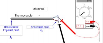
The general design of thermocouples installed in gas boilers is as follows:
- thermoelectrode with a junction of two conductors;
- extension contact (located inside the capillary tube, it also acts as a negative contact);
- positive contact (the locking dielectric washer is screwed onto it);
- fixing washer (dielectric that does not allow current to pass through).
The main advantage of this module is that in order for it to work together with the solenoid valve, it is not necessary to install a control unit or microprocessor. That is, the entire system works autonomously; there is no need to connect it to electricity. The average voltage generated by the module installed in gas boilers: from 15 to 60 mV.
We recommend reading on our website: Why a gas boiler does not reach the set temperature.
Principle of operation
The thermocouple is synchronized with the inlet valve - it is the one that gives the signal to stop the fuel supply.
It is based on the Seebeck effect. Its essence:
- two dissimilar conductors form a closed circuit;
- the junction points are affected by different temperatures;
- a thermoelectromotive force is generated in the circuit.
The latter does not appear immediately. The mechanism works like this:
- One side of the conductor is heated, which is why the electrodes move faster on it than on the cold side. As a result, higher energy flows to it.
- The energy acts on the electrodes, “pushing” them towards the cold conductor, which accumulates a negative charge.
- The hot side retains a positive charge.
- The charge accumulates until the potentials differ. Electrons from the cold side move back to the hot conductor.
- The final stage of the process is balancing.
The thermoelectromotive force is affected by the following factors:
- temperature indicator at the contacts;
- What is the conductor made of?
The working side of the thermocouple (the area where the conductors are connected) is immersed in a temperature-controlled environment. At this time, the non-working junction is connected to the measuring device. To measure potential differences, a millivoltmeter is used, which allows you to calculate the indicators in the usual degrees Celsius.
Additional Information! To connect a thermocouple to a measuring device, special thermocouple wires are used (their material is similar to conductors).
Diagnostics, repair and replacement
An initial check of the thermocouple is performed even without disassembling the gas boiler. The most common “symptom” is the extinguishing of the fire after releasing the ignition button, even when the boiler has already warmed up quite hot from the inside. If the fire goes out, it means the valve is not being held open. That is, the thermocouple does not generate enough voltage to open it.
Also read with this article: The main reasons why a gas boiler does not turn on.
The thermocouple is also checked by visual inspection. The presence of burns, holes or hollows is a clear sign of a malfunction.
How to test a thermocouple for functionality
To confirm the “diagnosis” you should check the thermocouple with a multimeter. How to remove the module is precisely indicated in the technical documentation for the boiler.
As a rule, this requires:
- unscrew the fixing nut near the solenoid valve;
- remove the sensor from the groove, disconnect the terminals (if provided);
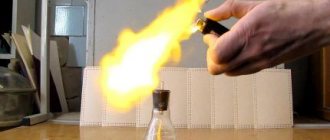
- heat the sensor in any convenient way (it is recommended to use a candle, but heat it so that the module body is completely enveloped by the flame);
- measure the voltage (apply one probe to the sensor body, the second to the output contact).
Expert's word!
Martyanov Pavel
Specialist in the field of gas equipment maintenance, 20 years of experience
Ask a Question
When checking the serviceability of a thermocouple with a multimeter, install one probe on the thermocouple body, the other on the lead end. The voltage should gradually increase and be at least 15 mV (in this case, the gas valve is in the open position and the wick does not go out).
As a rule, the operating voltage of the thermocouple after thorough warming up is 0.015 - 0.06 V. If the current is less than 15 mV, then this clearly indicates a malfunction of the sensor and requires its repair or replacement.
But to check the tester’s performance through a “dialer”, as is recommended on numerous forums, is not the best option. It is quite possible that due to overheating or oxide, the junction has “broken” and the conductor has shorted to the body. That is, there is actually an open circuit, but the multimeter will not show it.
Let's move on to cleaning the column
Turn off the gas supply valve to the boiler. Using wrench No. 10, unscrew the fastening screw under the boiler door and remove the door.
Disconnect the wire connecting the piezoelectric element and the ignition electrode.
Using key No. 10, unscrew the thermocouple clamp. Using wrench No. 9, unscrew the thermocouple from the valve.
Note: it is necessary to ensure that the thermocouple does not rotate while unscrewing.
We note the depth of insertion of the nozzle into the main burner so as not to disturb the boiler settings.
Using wrench No. 17, unscrew the nut securing the copper tube from the burner to the valve. Using wrench No. 10, unscrew the ignition electrode from the pilot burner and the copper tube from the pilot burner and valve. Using a flat-head screwdriver, unscrew the two screws securing the pilot burner.
The gasket installed under the pilot burner has become unusable. It will need to be replaced.
Remove the nozzle from the pilot burner.
Tip: if the nozzle is stuck, you can lightly tap the burner with a key.
We unscrew the four screws securing the main burner to the boiler body and the screw securing the housing to be able to remove the main burner.
Lowering the main burner down, remove the copper tube from the valve.
Remove the main burner.
Remove the thermometer sleeve from the boiler body.
Using wrench No. 10, unscrew the four screws securing the top cover of the boiler and remove it and the insulation sheet under it.
Unscrew the two nuts securing the flue to the boiler body.
Remove the terminals from the draft sensor.
We remove the gas duct.
We remove the swirlers from the boiler heat exchanger. We clean them with a brush. If necessary, use a metal brush.
Clean the outer part of the heat exchanger with a metal brush. We clean the heat exchanger channels with a brush to the full depth. Clean the bottom of the heat exchanger with a brush. We also clean the gap between the boiler body and the floor. We clean the loose debris using a vacuum cleaner.
Using wrench No. 13, loosen the screw that fixes the depth of insertion of the nozzle into the main burner and remove it.
We clean the burner with a brush and a brush, and clean its holes with a vacuum cleaner. We clean the flue of dust from the outside and inside.
We clean the outer surface of the nozzle with a brush, then clean the nozzle holes with a needle or wire.
Note: The needle should be smaller in diameter than the nozzle hole. Even a slight increase in the diameter of the nozzle hole can affect the combustion mode.
We install the main burner in place.
We install a copper tube with a nozzle and attach its nut to the gas valve.
Only after this do we secure the nozzle to the burner at the mark using wrench No. 13.
Note: this sequence is necessary to avoid stripping the threads in the valve body.
Finally tighten the nut of the copper tube with wrench No. 17.
Clean the pilot burner with a metal brush.
This is how the thermocouple should be installed in the pilot burner (the tip of the thermocouple opposite the flame).
We install the pilot burner on a new gasket.
Before installing the nozzle into the pilot burner, it must be slightly rubbed against the tip of the copper tube for better sealing. The nozzle should also be cleaned or purged.
We connect the copper tube to the pilot burner and to the valve using a number 10 wrench.
The remaining parts of the boiler are assembled in the reverse order. When connecting, the ignition electrode should not be clamped with a key; it is enough to do it by hand, since it is made of ceramic and can easily crack.
We carry out control washing of all compounds. It will be possible to check the tightness of the connections of the copper tubes to the main and pilot burners only when the boiler is turned on.
Advantages and disadvantages of using thermocouples
There are 2 key advantages of such modules:
- low cost of production;
- autonomous work.
Additional advantages of thermocouples installed in the boiler:
- can also act as a temperature sensor;
- wide range of operating temperatures (with a tungsten conductor they can work at temperatures above 2000 degrees);
- accurate measurement indicators;
- easy installation and replacement.
The only drawback: if the soldering is done poorly, the thermocouple fails quite quickly. And this happens even when soldering conductors in the factory. A visually unnoticeable microcrack will lead to the formation of oxide, and subsequently burnout. This is an additional reason why repairing a burnt-out module at home is impractical.
Read more on the website: Rating of the cheapest and most economical gas boilers for a private home (apartment)
Connection methods
The most common two methods of connecting a thermocouple to measuring transducers are simple and differential. In the first case, the measuring transducer is connected directly to two thermoelectrodes. In the second case, two conductors with different thermo-EMF coefficients are used, soldered at two ends, and the measuring transducer is connected to the gap in one of the conductors.
For remote connection of thermocouples, extension or compensation wires are used. Extension wires are made of the same material as thermoelectrodes, but may have a different diameter. Compensation wires are used primarily with noble metal thermocouples and have a composition different from that of thermoelectrodes. Requirements for wires for connecting thermocouples are established in the IEC 60584-3 standard. The following basic recommendations can improve the accuracy of a measurement system that includes a thermocouple sensor:
— A miniature thermocouple made of very thin wire should only be connected using larger diameter extension wires; — Avoid, if possible, mechanical tension and vibration of the thermocouple wire; — When using long extension wires, to avoid interference, you should connect the wire screen to the voltmeter screen and carefully twist the wires; — If possible, avoid sharp temperature gradients along the length of the thermocouple; — The material of the protective cover should not contaminate the thermocouple electrodes over the entire operating temperature range and should provide reliable protection of the thermocouple wire when working in harmful conditions; — Use extension cables within their operating range and at minimum temperature gradients; — For additional control and diagnostics of temperature measurements, special thermocouples with four thermoelectrodes are used, which allow additional measurements of circuit resistance to monitor the integrity and reliability of thermocouples.
DIY thermocouple repair
In 95% of cases, thermocouple repair is not practical or possible. Exceptions are the following situations:
- The cause of the malfunction is the presence of carbon or soot in the working area (where the solder is located). You can remove it with alcohol or other solvents. But grinding or treating with sandpaper is not worth it.
- Oxidized contacts at the junction with the terminals. They can be removed by careful sanding using “zero” sandpaper. Sometimes treating with alcohol helps.
If there is a visible burn or dent on the thermocouple, then the only repair option is to replace the sensor with a known good one.
We recommend reading on our website: The procedure for replacing an old boiler with a new one
But what you definitely shouldn’t do is fix the ignition button to force the gas supply valve to open. This is sometimes done when the temperature sensor module is faulty, and it is not possible to replace it right now. You need to understand that this carries a potential risk for everyone who is in the room where the boiler is installed. Indeed, if it fades (for example, due to blowing in from the chimney), the gas supply will not be automatically shut off.
Comments
Login to reply
Either no one is reading this, or one of two things. Interesting article. It's a pity, it's hard to read... The font is small and blurry. And in the pictures the text (in the explanatory frames) is completely unreadable. Apparently the material was ripped off from somewhere and copied poorly. I'd like to see the original.
Login to reply
reset your @ . I'll send it to you by email. article. if there is the same effect, I will correct it, I am the “aftar” of this creation. I don't do plagiarism. ). poked around personally..
Login to reply
It is not clear why the quality was lost. The original Word document looks flawless.
Login to reply
Login to reply
Good afternoon. I wanted to get an opinion or get advice from experts. The valve “stopped” working: I checked the thermocouple separately - it produces 40 mV from a regular burner; I checked the valve - it works exactly starting from 700 mV (dead AAA battery). I don’t understand what the problem is yet, because... It seems like the emf of the thermocouple is within normal limits (I’m very surprised by the reading of your thermocouple. Maybe there’s a problem there.). Because the valve operates from external power, I wanted to know whether the winding on the valve will not be covered when used in this way?
Login to reply
Good afternoon, I don’t know the indicators of the thermocouple, because... it failed, but the valve was triggered somewhere around 1V, “pulled” 400mA. My entire “kitchen” in the post, when powered by an external power supply, is relevant as a temporary solution to the problem during the period of purchasing (purchasing) a valve or thermocouple, or a kit in general. If you don’t think about buying them, unscrew the valve, remove the rubber gasket, remove the spring - the headache will disappear. ) The stove will turn into the USSR - a device. )Good luck.
Login to reply
PS. Try repairing the contact connections by removing the thermocouple, cleaning the seat, etc. connections between the terminal and the housing. It seems to me that your thermocouple is bad. Don’t worry about the valve winding. Increase the voltage until the valve operates - it will not take extra current.
Login to reply
Thank you for such a quick response! I have already cleaned the thermocouple contacts as much as possible, but, alas, or fortunately, there was nothing to clean there except carbon deposits. I have already taken measurements on a test bench without unnecessary details. Considering the gluttony of the valve, it also seems to me that the problem is in the thermocouple, but in contrast to this there is a table of TEDS of standard thermocouples (https://kipiya.ru/2008/04/04/tablica-termo-eds-standartnyx-termopar/, https:/ /temperatures.ru/pages/graduirovochnye_tablicy), where the maximum readings do not exceed 70 mV. That is why I began to look for help, because at the moment I have two impressions: the valve winding has deteriorated since it requires so much to hold and the thermocouple has deteriorated since it produces so little. But neither of these stand up to criticism. Or am I missing something. In general, there are two options left: either remove the valve or buy a kit. For now, I’ll just bypass the thermocouple using external power.
Login to reply
in terms of standards - the table focuses on industrial thermocouples, low-current (USSR-CIS standards), as for gas control - these thermocouples are “tailored” for bourgeois stoves. In fact, industrial thermocouples produce a LOW-CURRENT SIGNAL to electronic devices (with further amplification thereof) for control thermal processes. As for the t/p gas control, it (it was specially developed for the valve) produces a significant current to the valve, and the valve needs to overcome the resistance of the spring and also press down the gasket. In production there are hardening transformers (soldering of cutters). They produce 2 volts from the step-down winding between the contacts. The cutter is clamped and heated. The current is 400 - 600A. Approximately the gas control thermocouple is rated for a current of up to 500mA. Gas control cuts off the gas from the oven faucets, burners... It won’t go anywhere else until you open the faucet. If you look at the comments on the Internet about gas control, you can conclude that it is not perfect and is short-lived. = flush cistern with electronics unit. ) They install it to “make money” (IMHO). and there are no spare parts. There is a place for do-it-yourselfers to practice.
Differences from temperature sensor
In automatic gas boilers, in addition to a thermocouple, a temperature sensor can also be installed - it allows you to reduce the intensity of the flame when the user-specified temperature is reached.
Visually they are similar, so they can be confused. Main differences:
- the base of the temperature sensor is a massive cylindrical siphon in the shape of a sealed copper flask;
- the temperature sensor has a thinner capillary tube;
- the temperature sensor is installed near the water radiator (since it measures the temperature of the coolant, not the flame in the combustion chamber);
- The temperature sensor is connected to the automation valve.
Thermocouple Temperature sensor
The operating principle of a temperature sensor is also different. Inside the flask is a special liquid, which expands when heated, transmitting pressure to the automation, which, in turn, regulates the position of the valve.
We recommend the article: How to choose the right uninterruptible power supply
Expansion tank
To prevent the coolant from making a gurgling sound, the heating system must be completely filled.
But at the same time, the possibility of free expansion of the working environment when heated must be provided. This is why an expansion tank is installed.
The boilers are equipped with membrane-type tanks that do not communicate with the atmosphere (closed). Such a tank is divided by an elastic membrane into two parts, one of which is connected to the heating system, and the other contains air at a certain pressure.
The volume of the first part should be approximately 10% of the volume of the total coolant in CO. In the second part, you need to maintain a pressure 0.2 atm less than that observed in the CO when the circulation pump is running.
Types of thermocouples
Thermocouples for domestic gas boilers are predominantly chromel-alumel. They are among the cheapest to produce and can withstand heating up to temperatures of about 1500 degrees (in the combustion chamber it is on average 1000 - 1200 degrees). But they are also made from other materials. The most common:
- platinum-rhodium-platinum-rhodium (TPR);
- platinum-rhodium-platinum (TPP10);
- tungsten rhenium.
Mostly such variations are used in industrial boilers. The principle of their structure and operation is similar. The only difference is the maximum permissible operating temperature (as well as the current generated).
How to connect a burnt-out thermocouple of a gas boiler automation system
In theory, it is possible to solder a burnt-out module. Possible welding options:
- in a salt electric welding machine;
- using an acetylene torch;
- welding in coal or graphite powder (in a ceramic container).
But the welding current is approximately 80V 5A. This is the reading for a chromel-alumel thermocouple. That is, you can’t do without a laboratory autotransformer (aka LATR). And in addition to this, the likelihood that the seam will turn out uneven and when heating the module will not generate electricity at all is high.
The cost of a new thermocouple for a boiler is from 200 to 1500 rubles (depending on the model). The cheapest ones can actually be repaired at home if you have the right equipment for this. But expensive ones (with platinum or tungsten conductors), as a rule, cannot be repaired; they are simply replaced.
In summary, a thermocouple is a technically simple device that will protect against gas leakage in the event of a boiler extinguishing. The average service life of such a module is 5 years. Boiler manufacturers recommend that they be diagnosed at least once every 3 years.