Here you will learn:
- Selecting a room to place the unit
- What you will need to install a solid fuel boiler yourself
- General installation instructions
- Strapping schemes
- Connection to the heating system
- How to properly install supply and exhaust ventilation
- First start of the heating system
- Recommendations for effective operation
Installation of a solid fuel boiler should begin with the selection and arrangement of the boiler room. Then the installation itself, piping the boiler and connecting to the heating system is carried out.
Heating system with solid fuel boiler
Heat generators of this type operate on:
- firewood;
- peat;
- briquettes;
- coal
Loading and ignition of fuel is done manually.
System Features
The complexity of the piping is due to the specifics of the operation of a solid fuel boiler:
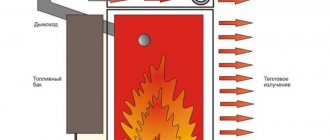
- Thermal inertia. Unlike gas and liquid fuel, the device cannot be quickly extinguished. Even with the air damper closed, the wood continues to burn for some time, releasing a large amount of heat. This increases the likelihood of overheating of the working environment and, as a result, its boiling and a sharp increase in pressure in the system. The piping is supplemented with a cooling coil, an emergency circuit and other elements for emergency heat release.
- Dependence of efficiency on performance. Maximum efficiency is observed only in rated power mode. If the boiler is extinguished by closing the air damper, fuel combustion becomes incomplete. This leads to a drop in efficiency and an increase in the amount of soot in the exhaust. A heat accumulator is integrated into the system, accumulating the energy produced by the boiler and releasing it in portions to the heating circuit.
- High concentration of sulfur and other elements in flue gases due to the composition of solid fuel. When steam condenses in the exhaust, water reacts with impurities and turns into an aggressive acid cocktail. For this reason, it is necessary to prevent the entry of a working medium with a temperature below +50...+55°C into the heat exchanger, otherwise its walls will soon be destroyed. A mixing unit is used, which, if necessary, adds hot water from the “supply” to the “return”.
The complexity of the piping is due to the dependence of efficiency on productivity.
Requirements for the boiler installation location
A solid fuel heat generator must not be placed in living rooms, bathrooms or kitchens.
A separate technical room is allocated for it, meeting the following requirements:
- presence of 1 entrance with a width of 80 cm;
- volume – from 15 m³ + 0.2 m³ for each kW of productivity, but not less than 7 m³;
- ceiling height – from 2.5 m;
- supply and exhaust ventilation must provide 3-fold air exchange and the supply of oxygen necessary for fuel combustion;
- fire resistance limit of walls, partitions and ceilings is 0.75 hours.
Fire extinguishing equipment is kept in the boiler room. It is not allowed to have a room or attic above it.
Ventilation holes are located:
- supply - no higher than 50 cm from the floor;
- exhaust - not lower than 40 cm from the ceiling.
Advantages of a heating system
Heating with solid fuel has the following advantages:
- Independence from external energy sources. Some models are 100% autonomous, as they do not require electricity.
- Low cost of fuel: 1 kWh from burning wood costs 0.9 rubles, coal - 1.6 rubles, while from liquefied gas and diesel oil - 2.5 and 2.8 rubles. respectively. In a number of regions, brushwood and dead wood can be obtained for free.
- Functionality. Many heaters are equipped with a hob.
- Safety. Solid fuels do not explode like gases.
- Comfort. Unlike diesel boilers, wood and coal boilers do not emit an unpleasant odor.
Heating with solid fuel ensures safety and comfort.
In the absence of a centralized gas supply, such installations are most popular.
Flaws
The negative aspects of the system include:
- Low degree of automation. It is difficult to regulate the temperature of the coolant; fuel needs to be added every 4-5 hours.
- Dirty exhaust. It is necessary to regularly clean the chimney and heat exchanger of soot.
- Complex harness. The presence of a heat accumulator, an emergency circuit and other elements leads to an increase in the cost of the system and an increase in the volume of installation work.
- Fire hazard. Due to the risk of soot igniting, sparks hitting building structures and fire escaping during backdraft, precautions must be taken.
Some disadvantages appear to a lesser extent in long-burning boilers.
They are capable of functioning on 1 tab for 12 hours or more; pyrolysis models produce relatively clean exhaust.
How to properly install supply and exhaust ventilation
There are several objective reasons why ventilation in the boiler room is necessary:
- supplying a sufficient amount of oxygen to the boiler to maintain the combustion process;
- removal of carbon monoxide that accidentally entered the room from the furnace outside the premises;
- compensation of the amount of air used during the combustion process.
Please note that to burn 1 kg of firewood you will need 4.6 m3 of air, and burning coal requires about 8-9 m3, based on the quality of the fuel.
Here are some tips for arranging a ventilation system:
- Openings for air inflow and outflow should be located on different sides of the boiler room. The supply opening is made at the bottom of the wall as close as possible to the heat generator, and the exhaust opening is under the ceiling.
- If the boiler is equipped with a smoke exhauster or a blower fan, you should not place the hood next to it (read: “How to choose a smoke exhauster for a solid fuel boiler - types, differences”). Otherwise, the draft will reverse, and the exhaust hole will become a supply hole.
- If the door from a residential building opens into a furnace room, then it is advisable to install a grille for the inlet opening in the door leaf. Warm air entering the boiler will improve the combustion process.
- The size of the exhaust opening should be smaller than the supply opening, since most of the incoming air enters into a thermochemical reaction and exits through the chimney in the form of CO2.
You can calculate the required size of the hood if you multiply the boiler power by 8 - we get the hole area in cm2.
Piping diagram without pump
In the absence of power supply or unstable operation of the network, a heating circuit with natural coolant circulation is constructed. Another name is gravitational. It does not require a pump, which means it is energy independent.
Principle of operation
The movement of the coolant through the pipes is ensured by convection - the tendency of a less dense heated medium to move upward under the influence of Archimedean force. Hot water is displaced from the boiler tank into the supply by colder water coming from the “return”.
Piping diagram for a solid fuel boiler without a pump.
Necessary tools and consumables
For installation you will need:
- perforator;
- levels – rack and spirit level;
- roulette;
- adjustable wrench "parrot";
- screwdrivers, pliers;
- for a polypropylene circuit - a special heater for welding plastic parts.
Materials needed:
- brackets for fastening pipes and radiators;
- dowels;
- tow or plumbing linen (FUM tape is not suitable due to the high temperature of the transported medium).
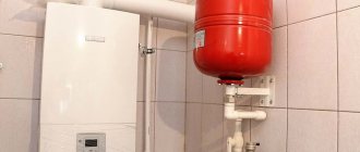
After heating, the volume of coolant will increase. To compensate, an expansion tank is inserted into the system.
Due to the absence of excess pressure in the gravity circuit, a cheap open type option is used.
Radiators, pipes, couplings and other fittings are also needed.
How to do
To create convection and minimize the hydraulic resistance of the circuit, it is built according to the following rules:
- The boiler is located at least 0.5 m below the radiators. In different rooms, marks at the same height are made using a spirit level.
- The first section from the supply pipe of the device is made vertical to the ceiling. This is an accelerating collector; it creates a strong convection pressure. The lowering is made along the corner of the room where the first radiator is located.
- Large pipes are used - with an internal diameter of 30-40 mm. As this parameter increases, the hydraulic resistance decreases.
- Horizontal sections are mounted with a large slope - 1 cm/m. This will make it easier for the cold liquid to drain back to the boiler.
The boiler is positioned to reduce hydraulic resistance.
The circuit must have a minimum of turns, fittings and other elements that increase hydraulic resistance.
The expansion tank is placed at its highest point. In order not to disturb aesthetics, the tank is often installed in the attic. In this case, the product must be insulated.
Minuses
The gravity system has a number of disadvantages:
- The length of the contour cannot exceed 30 m.
- Heat is distributed unevenly, radiators farthest from the boiler are colder than those closest to them.
- Due to the significant temperature difference between the “supply” and “return”, the heater experiences high loads.
- Large diameter pipes are needed, which increases the cost of the project and increases the volume of water.
- Through an open expansion tank, oxygen enters the working environment, causing corrosion of metal surfaces and airing of the circuit.
- It is impossible to operate the device in low-performance mode, which is required in the off-season.
Adding coolant volume to the heating structure
The working medium can be ordinary distilled water and antifreeze. Filling is carried out before starting the heating system in a private house, through the make-up unit located at the lowest point. This order is very important, since trying to add liquid through other pipes located above leads to the formation of air locks.
To ensure correct startup of the radiator, check the presence and functionality of Mayevsky taps. To do this, each of them is opened.
Then a certain procedure follows:
- It is necessary to open the air and bleed valves located at the highest point of the structure.
- Next, smoothly open the tap of the make-up unit, while keeping the water pressure low so that air pockets do not occur.
- After coolant begins to flow from the pipes of both valves, they are shut off.
- Mayevsky's taps remain open until working fluid flows out of them instead of air. This point is important, since starting the heating boiler if there are air pockets can lead to damage to the entire system.
If pressure testing has not been carried out previously, it is done during the process of filling with coolant. When starting the heating system, pressure gauges installed on the collectors, safety group, and boiler help control the pressure when filling with water.
Heating circuit with pump
The forced circulation circuit does not have the disadvantages of the gravitational system. The length of the pipes and their diameter can be any, you just need to install a powerful pump.
Tools and materials
Additionally you will need:
- phase indicator;
- wire cutters;
- stripper (device for removing the sheath from the conductors) or knife.
As for the tools, you will need a phase indicator.
The following materials and products are needed:
- copper wires with a cross-section corresponding to the current consumed by the pump;
- WAGO type terminals or self-insulating clamps;
- dielectric adhesive tape;
- cable box.
In addition to pipes, fittings and radiators, to install the circuit you will need:
- Diaphragm expansion tank. Due to the excess pressure created by the pump, the system is made closed, so the option for gravity heating is not suitable. You need a red membrane tank for process water. Blue for drinking is more expensive.
- Pressure gauge, air vent and safety valve. Together they are called a security group.
- Three-way valve with thermal head.
- Filter.
What to do with condensate
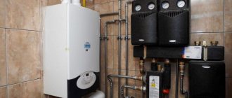
To avoid coolant with a temperature below +50...+55°C entering the boiler tank, causing the formation of acid on its walls, a mixing unit is installed near the heater.
The “supply” and “return” are connected by a jumper to a 3-way valve controlled by signals from a temperature sensor. When the coolant at the inlet to the unit cools below the critical temperature, the valve will change position, and a mixture of hot flow and cold flow will occur.
In this mode, the boiler is also started after a long period of inactivity. Until the coolant warms up, it circulates in a small circle through the jumper.
Instructions
The heating system is assembled according to the following rules:
- DN25 pipes are used; for long circuit lengths, DN32 pipes are used.
- Horizontal sections are laid with a slight slope, necessary only for drainage of the pipeline - 2-3 mm/m.
- They don't make an accelerating manifold.
- The safety group is installed on the side of the boiler supply pipe no further than 0.5 m from it. It is prohibited to place shut-off valves between the heat generator and the devices.
- A pump with a filter and a membrane expansion tank are connected to the “return” so that they operate in gentle conditions at a relatively low temperature.
- The pump is placed between the 3-way valve and the heater.
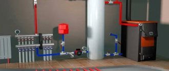
Heating diagram with a solid fuel boiler with a pump.
It is necessary to provide for the possibility of emergency discharge of excess heat.
For this use:
- a branch with radiators in unheated rooms (for example, in a pantry or on a veranda);
- a coil in the boiler tank, connected to the water supply on one side and the sewer on the other.
An automatically controlled valve is installed on the cooling element, which opens according to a signal from a temperature sensor.
Normative base
A heating boiler operating on solid fuel is subject to increased safety requirements. Equipment installation standards are given in SNiP II-35-76 Boiler installations (current edition SP 89.13330.2011).
According to the standard, hot water solid fuel boilers for public, administrative and residential buildings with a water heating temperature at the outlet of up to 115 °C can be placed in built-in and attached boiler rooms (placement on the roof is not allowed). In multi-apartment residential buildings they can only be installed in attached premises. Heating equipment must be factory-made, with built-in automation.
The maximum total thermal power of solid fuel boilers for a built-in boiler room should not exceed 1.5 MW. For an attached room this figure is not limited.
Requirements for the design of a chimney for the removal of combustion products, the installation of ventilation and water heating are regulated by the standard SP 31-106-2002 Design and construction of engineering systems of single-apartment residential buildings. It also stipulates the conditions for correct installation of the device (distance from the walls, boiler room finishing material), they must be taken into account together with the boiler operating manual.
Heating scheme with two boilers
Often, with a solid fuel installation, they use a low-power device that runs on a different type of fuel - an electric boiler or a gas boiler, powered from a cylinder.
This gives the following advantages:
- If the user forgets to add firewood, the second unit will start automatically and prevent the system from cooling down.
- The main heater operates at maximum efficiency.
The main equipment is selected not according to the lowest, but according to the average winter temperature. This makes it possible to operate it most of the time at nominal performance, and therefore with maximum efficiency.
Heating scheme with two solid fuel boilers.
The second boiler is used:
- in extreme cold;
- during downtime of the main heater due to lack of fuel or during maintenance;
- in the off-season (alone).
Different connection schemes are used:
- parallel;
- consistent;
- cascading
Features of installing a gas boiler in the bathroom
To place a gas boiler in a bathroom, the following conditions must be met:
- there should be a window in the bathroom;
- the boiler must have an open or closed combustion chamber.
A device with a closed firebox can be installed in a room without a window. Such units are equipped with a coaxial pipe. It simultaneously removes smoke from the boiler furnace through the inner pipe and supplies outside air into the combustion chamber through a channel located between this pipe and the outer casing.
When installing a boiler with an open firebox, a window is required. Otherwise, utility workers, firefighters and gas workers will not issue you permission for installation and will not connect the boiler to the gas pipeline.
Particular attention should be paid to the power supply of a gas boiler. Modern units are equipped with automation and electronics, so there should not be large voltage surges in the network.
Therefore, it is advisable to connect the equipment to the network using a reliable voltage stabilizer. This will protect the unit from damage.
Tying of primary and secondary rings
This scheme is used in complex systems with a large number of consumers operating in different temperature conditions.
Installation procedure:
- A short circuit with the main heat removal devices (for example, lower floor radiators and an indirect heating boiler) is connected to the boiler. This is the primary ring.
- Loops are connected to the circuit - “warm floors”, floor branches with radiators, etc. These are secondary rings.
Each part is equipped with its own circulation pump. In the primary ring, the pump operates constantly, and the coolant moves continuously here. If necessary, blowers are started in the secondary loops, causing the circulation of the medium here too. Consumers powered from them receive heat.
If the pump in the secondary ring is turned off, the movement of water in it will stop, since the pressure at the points of connection to the primary circuit is the same. To do this, they are spaced at a distance of no more than 4 pipeline diameters.
Scheme of binding of primary and secondary rings.
The temperature in the secondary ring is controlled in 2 ways:
- starting and stopping the pump;
- changing the speed of its rotation.
Scheme of a closed circuit with gravitational circulation
Often a combined system is built for a solid fuel boiler. It has a pump, a closed expansion tank with a membrane and a safety group, but is created according to the rules for circuits with natural circulation - with large pipes and slopes, an accelerating manifold, etc. This is done in case of a power outage.
To switch to natural circulation, you need to exclude the pump from the circuit. To do this, make a bypass with manual ball valves.
Closed loop wiring diagram.
Purpose of the device
A long-burning solid fuel boiler is a complex unit that heats circulating water by burning various fuels (wood, coal, sawdust, peat, pellets, etc.).
The boiler can be single-circuit, used only for space heating, or double-circuit, capable of not only heating the building, but also heating water using a storage or flow method. For this purpose, a built-in DHW system is used.
Selecting the optimal system
When developing a project, the following factors are taken into account:
- availability and stability of power supply;
- presence of consumers with non-permanent operating hours.
In suburban areas, where the energy infrastructure is stable and can be quickly repaired in the event of an accident, a system with forced circulation of coolant is preferable. In remote areas, long outages are possible; here it is better to assemble a combined circuit.
And only in field conditions, when there is no centralized power supply, a natural circulation scheme is used.
If there are temporarily working consumers, for example, a “warm floor” in a swimming pool, the following schemes are used:
- On large objects - with primary and secondary rings.
- On small ones - radial.
In the second case, separate branches from the common collector are laid to the heat removal devices, installing control valves on them. All “returns” from them also converge at 1 point.
Optional equipment
To increase efficiency, a heat accumulator is installed between the boiler and the heating circuit - a water-filled container in a mineral wool shell. The solid fuel is constantly operated in nominal performance mode with maximum efficiency, heating the contents of the tank to +95°C.
A heat accumulator is installed to increase efficiency.
Hot water is withdrawn from the battery automatically as the medium in the circuit cools.
In a country house and other small buildings, a hydraulic arrow is used to connect the “warm floor”. This is a collector installed vertically. Thanks to this orientation, the temperature varies with height; the environment below is colder. Radiators are connected to the upper part, and “warm floors” are connected to the opposite part.
Rules for arranging a boiler room
It is recommended to cover the floor with ceramic tiles and lay out the walls with refractory bricks. This measure will reduce the likelihood of a fire.
The floor with a wooden or other combustible covering within a radius of 1.2 m from the center of the boiler combustion door is protected by a 1.2 mm thick steel flooring on a thermal insulating substrate made of asbestos or basalt cardboard.
The walls are covered with fire-resistant plaster, for example, based on vermiculite. Layer thickness – 25 mm.
The following distances are maintained between the heater and the walls:
- from the combustion door side – 2 m;
- on the sides and back - 0.8 m.
The boiler room is equipped with emergency and emergency lighting. In case of depressurization of the circuit, it will be equipped with a ladder or pit 0.5 m deep connected to the sewer.
It is advisable to lay the walls of the boiler room out of brick.
With a heat generator power of up to 30 kW, firewood and coal can be stored near the boiler room in boxes made of fireproof material. The minimum distance to the firebox is 1 m.
If the boiler’s productivity is higher, an isolated, dry and ventilated room is allocated for the warehouse.
Build process
The process of creating a boiler includes several stages. When manufacturing each element, it is worth taking into account the special operating conditions of the product being manufactured.
Air supply device
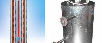
We cut a section from a thick-walled pipe with a diameter of 100 mm, the length of which will be equal to the height of the firebox. We weld a bolt to the bottom. From a steel sheet we cut out a circle with the same diameter as the pipe or larger. We drill a hole in the circle large enough to pass the bolt welded to the pipe. We connect the circle and the air duct pipe by tightening the nut onto the bolt.
As a result, we will get an air supply pipe, the lower part of which can be closed by a freely moving metal circle. During operation, this will allow you to regulate the intensity of firewood combustion and, consequently, the temperature in the room.
Using a grinder and a metal disc, we make vertical slits approximately 10 mm thick in the pipe. Through them, air will flow into the combustion chamber.
Housing (firebox)
The body will require a cylinder with a sealed bottom with a diameter of 400 mm and a length of 1000 mm. The dimensions may be different, depending on the available free space, but sufficient for laying firewood. You can use a ready-made barrel or weld the bottom to a thick-walled steel cylinder.
Sometimes heating boilers are made from gas cylinders for a longer service life.
Chimney
In the upper part of the body we form a hole for the removal of gases. Its diameter must be at least 100 mm. We weld a pipe to the hole through which the exhaust gases will be removed.
The length of the pipe is selected depending on design considerations.
Connecting the housing and the air supply device
We cut a hole in the bottom of the housing with a diameter equal to the diameter of the air supply pipe. We insert the pipe inside the body so that the air vent extends beyond the bottom.
The air supply pipe should end a few centimeters before the start of the chimney.
Heat Dissipation Disc
We cut out a circle from a metal sheet 10 mm thick, the size of which is slightly smaller than the diameter of the body. We weld a handle made of reinforcement or steel wire to it.
This will greatly simplify the subsequent operation of the boiler.
Convection hood
We make a cylinder from sheet steel or cut a piece of pipe, the diameter of which is several centimeters larger than the outer diameter of the firebox (body). You can use a pipe with a diameter of 500 mm. We connect the convection casing and firebox together.
This can be done using metal jumpers welded to the inner surface of the casing and the outer surface of the firebox, if the gap is large enough. With a smaller gap, you can weld the casing to the firebox around the entire perimeter.
Lid
From a steel sheet we cut out a circle with the same diameter as the firebox or a little larger. We weld the handles to it using electrodes, wire or other available means.
Considering that the handles can become very hot during operation of the boiler, it is worth providing special protection made of material with low thermal conductivity.
Legs
To ensure long burning, we weld the legs to the bottom. Their height should be sufficient to raise the wood-burning boiler at least 25 cm above the floor level. To do this, you can use various rolled products (channels, angles).
Congratulations, you have made your own wood-burning boiler. You can start heating your home. To do this, just load the wood and light it by opening the lid and heat dissipation disk.
Arrangement of a pellet bunker
There is a type of solid fuel boiler that does not require frequent loading of fuel. They operate on pellets - granules made from pressed waste.
You can make a bunker for storing them yourself from the following materials:
- tin;
- plywood;
- fabrics on a metal frame.
An electrically driven screw feeder is connected to the tank to automatically feed pellets into the burner. It is better to purchase a 2-screw model with an air gap, which eliminates the movement of fire into the bunker during reverse thrust.
Results
You can install the heating system of a hot water boiler yourself. But for this you need to correctly select and calculate its parameters. Initially, a connection diagram for a solid fuel boiler is selected that is optimal for a particular facility. Then you need to select radiators, calculate the hydraulic resistance of the network, determine the diameters of the network pipelines, calculate the volume of water in the system, and select the power of the equipment. To avoid annoying mistakes, it is better to entrust this work to specialists - the calculation of the heating system is carried out at the design stage in terms of air conditioning.
Additional recommendations
To prevent the heat exchanger from becoming overgrown with scale, fill the system only with demineralized water. Often homeowners collect rainwater for these purposes.
For the same reason, it is better to purchase a model with a cooling coil in the heat exchanger, and not with water supplied directly to the tank.
Do not smoke in a house with an aluminum radiator system. Hydrogen is formed in them, which comes out through an air vent or Mayevsky valve.
During the period of inactivity of the heater, the heat exchange in its tank takes on the opposite direction. To ensure that the water in the circuit cools more slowly, it is recommended to create a bypass with taps through which the medium will move around the device.
By the way, it’s not difficult to make a solid fuel boiler with your own hands.
Firewood quality
The best firewood for a solid fuel boiler has always been oak firewood. Due to its high quality, these raw materials belong to the elite class. The cost of oak firewood is high, so it is not affordable for everyone. But such firewood is often indispensable when it comes to the taste of baked bread, pizza or other pastries. Here oak logs are simply irreplaceable.
Let's look at the characteristics of firewood from different types of wood:
- Oak: an elite, expensive variety. Burns powerfully, giving off a huge amount of heat;
- Birch: Best quality/cost ratio;
- Alder: excellent firewood, the house warms up quickly. In addition, the ancestors considered alder firewood to be “medicinal”, since in a house heated with its help, people were less likely to get colds;
- Pine: hot and aromatic firewood that burns well due to its resin content.
