Not so long ago, three-phase input to a consumer’s facility was considered the prerogative of industrial enterprises. Although, if you look in detail at the energy supply diagrams of apartment buildings, it turns out that residents receive the coveted 220 volts from the three-phase power supply panel. Surely, many of you have noticed that in the event of an accident on an electrical main, power may not be lost in the entire house at once, but as if in a checkerboard pattern. At the same time, in conversations among repairmen the phrase is heard: “the second phase has been knocked out...”.
This means that consumers in a high-rise building are distributed into three groups (usually with an even load). A three-phase power cable (four-core, excluding a separate working grounding bus) with a common meter and a single machine was installed at the facility. The output has 3 lines with a voltage of 380 volts between them, and a working zero. Next, in each of the three directions, a two-core power wire is laid (without taking into account the working grounding), on which the usual 220 volts are between phase and zero.
Since consumers in their apartment distribution panels have access to only one phase, such a power supply still does not apply to three-phase.
However, there are residential buildings (including apartment buildings) in which the entrance panel looks the same as in the previous illustration. For example, houses that do not have natural gas. Three-phase electric stoves are often installed in apartments. Three phases may be needed in rooms with an electric water heater or heating boiler. Such electrical equipment can also use three phases with a voltage of 380 volts.
Combined wiring
Combined wiring
This method is used when you need to connect additional ones from one electrical outlet, but you cannot drill into the walls. The procedure for installing and connecting wires in this case is as follows:
- Power outage. It is necessary to de-energize the entire apartment or room in which the work will be carried out. Using a tester, you need to make sure that there is no voltage.
- Removing the protective cover from the main power point.
- Removing the socket by loosening the retaining contacts.
- Connecting wires to the new power point.
- Next, it is checked whether the limiter will not squeeze the wires. If it interferes with the cables, you need to carefully break off a small piece from the socket box or wall to the size of the wire.
- Reinstalling the socket.
- Creating a hole in the decorative cover for the wire.
- Installing the cover.
Installing an outdoor (external) outlet
These types of sockets are very popular in wooden private houses and country houses. To install such an outlet, you do not need a socket box. The socket is attached to the wall using self-tapping screws.
As for the electrical cable, it is laid in cable ducts or simply along the wall with fixation using special plastic brackets.
An example of cable channel installation is presented below:
In the photo above the cable channel is open
An example of self-tapping screws for attaching a cable channel
For example, consider the process of installing and connecting a double outdoor socket:
Step 1.
Remove the front panel of the socket.
Step 2.
We fix the socket to the wall using self-tapping screws and connect the power cable:
Step 3.
In the front panel of the socket you need to make a small cutout for the cable, as shown in the photo below. To do this, it is convenient to use metal scissors:
Step 4.
We install the panel in place and close the cable channel.
Basic mistakes
Brown wire - phase, blue - neutral, yellow-green - ground
Installing an additional outlet is usually not difficult. But beginners can make the following mistakes:
Wrong choice of wire cross-section. You need a cable of the same thickness as the main outlet. Using a wire made of a different material. Connecting two different wires causes additional difficulties, and the contact itself is less reliable. Violation of the order of connecting wires
Particular attention should be paid to the grounding conductor. If it is not available in the house (especially in old buildings), it is better to purchase sockets without ground. Unreliable contact
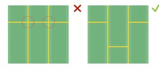
You need to familiarize yourself in advance with the existing methods of creating a contact and practice connecting on spare sections of wires. Installing wires diagonally. Standards only allow vertical cable routing.
There is also a risk of buying a model that is not suitable in design. This is not a critical error from a technical point of view, but can disrupt the overall concept of the room. Therefore, when purchasing, it is recommended to select the color of the product, its shape and size in advance. Manufacturers of electrical products offer a wide range of products; any buyer will find a product that suits the style.
Caliper location
The next question is how to correctly position the socket support inside the socket box - with the terminals down or up.
Some are guided by the inscriptions on the case. They should be legible and not upside down.
On the one hand, this is quite logical. But in reality, there is not much difference. This is not reflected in any way in the regulatory documents.
Therefore, mount it in the way that is convenient for you. For example, focus on the incoming cable.
Sockets in drywall
This is both hidden and open wiring - it belongs to the first category because the wires are not visible, and it falls into the second category because the wires are not walled into the wall and can be reached. In addition to standard tools (unless you are installing a socket block), you will need steel wire for installation. The procedure is as follows:
- The socket and socket box are removed from the wall. They are screwed to the drywall, so there is no need to break anything.
- The steel wire is inserted into the hole and pushed in the direction where the new socket is planned to be installed. At this stage, you just need to make sure that there is a gap between the plasterboard slabs, profiles and the wall into which the corrugation with wire will pass (wiring unprotected from mechanical damage cannot be left inside).
- If you can find the way with the wire, then a hole is drilled in the right place for a new socket box. A strong rope is screwed to the wire and it is pulled back.
- Then, using a rope, a corrugation is pulled between the sockets, the wires are inserted into it and connected.
Installing an indoor outlet
To install an internal socket, you must first prepare a seat - a socket box. Socket boxes may vary depending on the wall design.
So for a concrete or brick wall you need to use a simple socket box, which is secured using building mixtures, and for a hollow wall made of plasterboard you need a socket box with special clamping claws (see photo below):
Also, depending on the type of wall, the method of laying the cable will depend.
For example, a special recess is made in a concrete or brick wall - a groove. The electrical cable is fixed in the groove using building mixtures or fasteners, and then covered with putty or plaster.
If the wall is a metal frame covered with plasterboard, then the electrical cable is laid inside the wall during the installation process.
In this case, it is recommended to lay the cable in a protective corrugation. An example of laying an electrical cable in a corrugated structure inside a gypsum plasterboard partition.
Thus, the whole difficulty of installing and connecting an internal outlet lies in laying the cable and installing the socket box. You will find step-by-step instructions for gating walls and installing socket boxes in concrete and drywall by following the appropriate links.
Let's assume that we have already laid the electrical cable to the location where the socket is installed and let's look at the connection process in detail:
It is enough for the electrical cable to protrude from the socket by about 10-15 cm
Step 1.
Before installing an electrical outlet, you must turn off the line through the circuit breaker and make sure that there is no voltage on the cable connected to the outlet using an indicator screwdriver:
Step 2.
We remove the PVC insulation and expose the cable cores by 8-10 mm. To remove the insulation, you can use a simple construction knife, and it is also very convenient to use special pliers directly to expose the conductors:
Step 3.
Remove the front panel of the socket to gain access to the bolts that will allow you to fix the socket in the socket box:
Step 4.
We insert the cable cores into the corresponding holes of the socket until they stop and fix them using special bolts. We make sure that the cable cores are securely fixed:
Step 5.
We install the socket in the socket box and secure it. An electrical outlet, as a rule, can be fixed in a socket box in two ways: using the socket box bolts (No. 1 in the photo) and using its own clamps - “spacer legs” (No. 2 in the photo). For reliability, we use these two methods at once:
Step 6.
Reinstall the front panel. At this point, the installation of the internal outlet can be considered complete.
Single and double sockets are installed and connected absolutely identically
Below are photos of connecting a single internal socket ]Lezard[/anchor]:
Installing a block with two and three keys
Installation of such a block makes it possible to control two light sources in different rooms, or two in one room. In this case, not 4 wires are supplied from the distribution box, but five.
- The phase is connected to the jumper of the switching block.
- Only the neutral wire and the grounding conductor are attached to the socket contacts.
- Then the two remaining conductors are connected to the switch contacts.
- In the distribution box, twists are made of the cores that supply the core and those that go to the lighting fixtures.
Three-key combined devices are the best option for small apartments. They often have a bathtub, a toilet and a kitchen nearby, and the lighting is switched on on one wall. If there are three keys, then you will need a cable with six cores, three of which are also connected to the switch terminals.
What is high voltage power used for?
For the same reason that main power lines operate under a voltage of 10 thousand volts. To provide a certain load (power of an electrical appliance), there are two ways: increase the current strength at a reduced voltage, or vice versa: by increasing the voltage, you can reduce the current in the circuit. To save power cables, it is more rational to supply the consumer with 380 volts instead of 220.
The benefit is obvious: the current is lower, the wires heat up less, and their cross-section can be reduced. Likewise, switching devices are designed for lower current.
Accordingly, to connect the final electrical installations, there must be a three-phase socket in the room.
Important! If you have a 3-phase socket installed in your house, connecting powerful single-phase consumers to it without specially switching the input terminals is prohibited!
In this case, load imbalance occurs, this negatively affects the operation of generating devices and can damage the protective automation.
Wire selection
The wire is selected according to this principle:
number of cores If you decide to install a socket with a grounding contact (see above), it is connected with a 3-wire wire. Otherwise, use 2-wire;
material. In general, when installing wiring, it is recommended to use copper cable - brand VVGng (in non-flammable insulation) or NYM (imported analogue). Copper is superior to aluminum in electrical conductivity and ductility (the aluminum core breaks off after several bends). But with a daisy chain connection, a wire made of the same material is used that is connected to the first outlet. If a copper conductor is directly connected to an aluminum conductor, when current flows, both materials are destroyed due to an electrochemical reaction. A special neutral alloy adapter is required. Aluminum wires (brand AVVG, etc.) are found in old houses
Therefore, before installation, it is important to open the existing outlet and see what it is powered by;
core section Also selected according to the wire connected to the first socket (when using cables of the same material)
There is no point in using a wire with a larger cross-section, since the throughput of the “chain” is still determined by the capabilities of its weakest link.
For household sockets, the minimum recommended core cross-section is 2.5 mm2 (for copper wire). Such cables, when laid hidden, can withstand a current of up to 16 A (when open, even more due to good heat dissipation), so you can safely plug in any device into the outlet, except for particularly powerful ones - an electric stove and an instantaneous water heater.
If the first socket of the loop is powered by a wire with 1.5 mm2 cores (mainly used in lighting networks), you should think about replacing it. Otherwise, only the lowest-power devices can be connected to the loop sockets.
Stripping length
When stripping the outer sheath of the cable, there is no need to try to remove it to the maximum depth, i.e. all the way to the wall of the socket.
Always try to leave a few millimeters. This way, the core insulation will be protected from chafing or crushing by the sharp edges of the socket box.
It is very convenient to do this on a round NYM cable using a special Jokari puller.
Make a circular cut, and then immediately a longitudinal one. After which, even in cramped conditions, the shell is easily pulled out.
With flat cables of the VVG brand and an electrician's knife with a heel, such a trick will not be possible.
And if it is a GOST cable, and not a TU cable, then even more so.
As a rule, a knife with a heel cuts the outer insulation right up to the wall of the socket box.
That is why many electricians like the NYM cable brand and not the VVG cable brand. Because of the convenience of cutting and ease of working with it.
Although each brand has both its advantages and disadvantages.
By the way, in rare cases you can also find a VVG cable with a round cross-section.
How much insulation should be removed from the core itself before inserting it into the contact? Much, of course, depends on the brand of the outlet.
Some models even have a template that is very easy to navigate.
But usually, the exposed part of the core should not exceed 8-10mm.
The length of the wires protruding from the socket box is selected based on:
- ease of installation
- socket depth
You must understand that the length that you leave will be useful in the future for convenient dismantling, pulling out and carrying out some kind of revision work. Or even replacing the socket with a different model.
As a rule, leave a length equal to the width of 3-4 fingers.
Some tips
Since these units are still considered new, it is necessary to provide several recommendations regarding how to connect an outlet with a switch.
- If installation is planned in a wooden house, then the socket box should be metal.
- When the unit is mounted near a doorway, the part that is the switch is located closer to the door.
- If you don’t have enough knowledge in electrical engineering, no work experience and no confidence in the correctness of your actions, it is better to entrust the work to professionals.
- Often home craftsmen make various mistakes when connecting. The most “popular” mistake leads to the fact that the socket is in working condition, but the switch refuses to function. In this “severe” case, the incorrect distribution of wires is to blame - confusion with the phase and neutral on the socket. The solution is to connect the phase conductor to the jumper and return the neutral conductor to the socket.
Sometimes such designs become the only possible solution, and in this case the owners no longer have to think about the pros and cons of the blocks. Understanding how to connect an outlet with a switch will make it possible to cope with similar work in the future.
An example of such a connection can be seen in this video:
Main varieties and designs
Design solutions of modern sockets are limited by certain technological frameworks. However, these products are produced in a wide range, represented by various models and modifications.
Any triple socket in one socket box is structurally available in two main versions. In the first case, a common frame is used, closed with a single lid, and in the second, a common body-lid covers three sockets, spaced separately. Among such designs, products with switches are in high demand, significantly increasing the functionality of the network at a given location.
Serial and parallel connection
The daisy chain method is otherwise called serial connection of sockets. In contrast, the parallel connection method provides for powering each outlet with a separate line from the distribution box (for the most powerful devices, a line is drawn from the distribution board).
Advantage of daisy chain connection:
- less dirt and dust is formed: the groove is made in a short area between the sockets;
- for the same reason, labor costs are reduced;
- cable costs are reduced.
But there are also important disadvantages:
- low reliability: if the wire burns out, all subsequent sockets of the loop become inoperable;
- limited power: the maximum permissible current, determined by the cross-section of the cable cores of the first socket (at 2.5 sq. mm 16 A), is divided by all devices included in the loop (with a parallel connection, each socket can consume the maximum current);
- startup and shutdown of the device are accompanied by more noticeable voltage drops in adjacent sockets than with a parallel connection.
Three-phase socket device
Contacts of a three-phase socket
Devices may differ significantly in appearance - design, location of input holes, and other points. The minimum number of contacts for reinforced sockets is four. Three - phases, one - grounding. Connectors with a plug form detachable contacts.
To understand how many microcontacts are required in a particular case, it is necessary to determine several points:
- for the triangular phase, four-contact devices are used;
- star circuit - at least five contacts;
- seven holes - required when maximum protection against voltage surges is needed: three phases, three zeros, one PE grounding are connected.
The four-pin connector is used in delta load connection circuits. Five contacts are used in both the “triangle” and “star” cases. Power is connected only to certain terminals. After this, you can connect all kinds of electrical devices through the outlet.
Wires connected to a three-phase or two-phase outlet must have a diameter of at least 2.5 square millimeters. In the case of high loads, the diameter requirement can increase to 6 square millimeters.
How are sockets and switches connected?
We hope that the general part of the circuit structure is clear to everyone. Now let's see how the electrical points are connected to it.
Connection diagram for luminaires via a two-key switch
So, we have a group power wire that comes into the junction box. This wire can have two or three cores. According to modern standards, three-core wires are used for these purposes. It is worth saying that the connection diagram will not change much depending on the number of available wires.
- All three wires will have different color markings. White or pink is phase, blue is zero, and yellow-green is ground. Be careful and careful when making connections, as there is always a chance that the electrician connected the wires to the machine incorrectly. Pre-check the wires for voltage with a tester.
- Let's start the analysis by connecting the outlet. The phase and neutral are connected to its power contacts, while the “ground” is connected to the grounding contact. That is, to connect it to the network, all three wires are used.
Grounding is required to transfer charge from the device body to the ground loop, which avoids electric shock.
- With the switch, everything is a little more complicated, since this part of the circuit also includes a lighting device.
- So, we have three wires in the box - they are separated from each other and we can clearly see the color coding, which corresponds to the actual parameters of the circuit. A two-wire or three-wire wire is laid from the distribution box to the switch box - the first is taken for a single-key switch, and the second for a two-key switch. If there are even more keys, then the number of conductors increases proportionally.
- We screw the stripped ends of the wire to the switch terminals. Let us say right away that only phase wires will be suitable for this device, regardless of their number. The fact is that the task of the switch is to break the circuit and stop the supply of electricity to the lighting fixture. That is, the ends of the wire are input and output.
- Already in the distribution box, one core connects to the phase conductor of the group wire. The second core is connected to another wire, which is extended to the lamp as a phase. This wire also has two or three cores - the second is connected to zero according to the color marking, and the third is connected to ground. We do the same if the switch is two-key, but according to a slightly more complicated scheme. Here the task is to divide the lighting fixtures into groups and turn them on separately.
Connecting wires in a junction box
Video - Connecting a socket and switch
If you have read the above carefully, then you already understand that the connection diagrams for the points are completely different and there is simply no zero or grounding in the switch box so that you can connect the outlet. So how can this be done? Let's name all acceptable methods.
Advantages and disadvantages of a three-phase power supply system
It is no secret that three-phase power supply to a private home is becoming more and more relevant, and this is connected not only with the voltage level. Let's look at all the advantages of 380 Volts and here is a list of them:
- Connection of the most common asynchronous electric motors with a squirrel-cage rotor in everyday life and in production. When connected to a single-phase circuit, their power, torque, and efficiency are lost. After all, they were originally designed for three phases. The use of such electric machines in a private home may be necessary when installing a grinding, drilling or woodworking machine and other types of equipment. An owner who has the skills to operate such equipment will always find a use for it. A powerful pump is always useful at the dacha, so running 380 Volts won’t hurt here either.
- By connecting three phases, the owner of a private house receives, by and large, three independent single-phase networks at once, which he can dispose of at his own discretion. To do this, in order to obtain a single-phase voltage of 220 Volts, you need to connect one wire to the phase and the other to zero. It will be called phase. The voltage between two phases is 380 Volts and is called linear.
- In the event of a breakdown or emergency at a distribution substation, one or even two phases may burn out. At the same time, the owner of a private house with three phases will at least have lighting and a refrigerator working. It must be remembered that for three-phase motors, operation on two phases will entail its inevitable failure.
Keep in mind that there are pitfalls here too. A three-phase network is needed if the power of a single-phase network is not enough. And even if single-phase is not enough, there is no need to rush to connect three phases, it is better to clarify the possibility of increasing the power limit for a single-phase network - this procedure is much simpler than coordinating and connecting three phases. Three phases must be connected if it is necessary to power three-phase electric motors that cannot operate in single-phase mode, or if a large number of electrical appliances and equipment are used simultaneously, for example, if the house has a large household or some small-scale production has been established.
Several other disadvantages of the three-phase power supply system should also be noted. One of the disadvantages is the need to distribute loads evenly across each phase. The second drawback is the great difficulty in connecting, purchasing another shield, protective devices, etc. The third drawback is a great danger from the point of view of electric shock, since the house will have not only a single-phase voltage of 220 V, but also a linear voltage of 380 V
As you can see, the advantages of powering the consumer from a 380 Volt network are not always obvious. Now it’s worth figuring out what documents are needed to connect a three-phase network. This is what we will talk about now.
How to choose the right method
Connecting two outlets to one cable
To choose parallel or serial connection of outlets, you need to calculate several parameters: the amount of money that can be spent on electrical wiring, equipment power and wall decoration (the ability and desire to redo repairs in case of breakdowns).
The optimal way is to connect two sockets to one wire of a panel or distribution box - a parallel connection. If the room does not have a large number of sockets and appliances (for example, only a TV), the loop method is suitable.
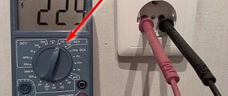
Voltage check
Power parameters are determined with a multimeter or voltmeter. Between any phase contacts the readings are about 380 V, between the working zero and the phases the voltage is 220 V, between the protective zero and the phases it is also about 220 V. If all the indicated numbers match, then the three-phase socket is ready for use.
Thus, you can independently supply power to a three-phase outlet or eliminate small faults associated with such equipment, avoiding errors associated with connecting the cable.
Is it possible to connect sockets in series?
Connecting sockets in series mode has a number of disadvantages and limitations. In a large room and a significant number of powerful electrical appliances, this method cannot be used - the load is too high. It is better to parallel the sockets or use the ring type. The recommended quantity per chain is 5-6 pieces.
Another disadvantage is the uneven distribution of voltage at power points. Each outlet accounts for a portion of the total electrical flow. Therefore, serial connections are not used in residential and industrial premises. But you can use it in Christmas tree garlands and others.
Electricity metering board diagram 380V for a private house 15 kW
When connecting a private house to the power grid, you will definitely need to obtain technical specifications for connection from the electricity supply company (Mosenergo, Lenenergo, Sverdlovenergo, etc., depending on the region). It is this document that contains the main characteristics of the electrical network available to you, including the requirements for the electricity metering panel.
In this article we will examine in detail the diagram of a typical metering panel, as well as its modifications, which require collecting the requirements of technical specifications.
In such cases, the standard network parameters for connecting a private home are:
— 3 phases
— Voltage: 380V
— Power allocated: 15 kW
— Input cable: SIP 4-core (3 phase conductors and PEN)
I would like to note that one of the main tasks of technical specifications is not only to ensure the safety of the electrical installation, but also to prevent the possibility of theft of electricity by consumers.
That is why all protection or switching devices in the electrical panel located before the electric meter must be protected from the possibility of illegal connection. Usually they are hidden in separate boxes, which are sealed when connected.
In addition, the technical specifications require that the metering board be placed in a place accessible for inspection - on the border of the site, on a lighting pole or fence.
Most often, such external panels are used exclusively for accounting, without additional capabilities, and provide only basic functions. The main distribution board (PDB), in this case, is installed inside the house, where all consumers are divided into groups, the load is distributed, the appropriate automatic protective equipment is installed, etc.
All the diagrams presented below will be designed for the two most popular grounding systems in private homes, TT and TN-CS. Under each connection option there will be links to step-by-step assembly instructions, with detailed comments.
If you have not decided which grounding system to choose, the following information will help you:
TN-CS is the grounding system recommended by the rules. It has a number of disadvantages; it is worth using it if you are confident in the condition of the electrical networks suitable for the house, if they are new enough and regularly maintained.
TT is a relatively safer system. The main disadvantages include only the high costs of installing protective equipment and installing a ground loop, as well as regular maintenance. Which, for safe operation, must always be maintained by you in working condition.
You will learn more about the differences in the design of grounding systems in one of the following articles. Subscribe to our VKontakte group and stay tuned for new materials.
Installation procedure
Drywall is a fragile material and must be handled with care.
Before you begin installing sockets yourself, you will need to read the installation instructions. The easiest way to consider an example is when they are installed in a plasterboard wall. The work order in this case looks like this:
- Take an electric drill with a “crown” type attachment, through which a hole for the socket is prepared in the selected location. Its diameter must match the size of the plastic case (glass) used as a mounting base and fixed directly at the installation site.
- The mounted socket is placed in the glass and secured in it using long spacer screws.
- It is necessary to connect the phase and neutral conductors brought out to the contacts, and then close the product with a decorative cover.
At the final stage of work, you should supply power to the line and check the socket for functionality - connect any household appliances to it.
To correctly connect several outlets in a row at once (with a cable), experts advise paying attention to the following points:
- The wire from the phase terminal of one socket unit is pulled to the same contact of the next product, and so on. To such a cable you can add the entire set of sockets installed in a given room.
- The same is done with the neutral conductor, laid from the corresponding contact to the second and subsequent products mounted on the wall.
- If there is a grounding conductor, the same operations are performed with it.
The advantages of this connection method include ease of implementation and economical use of consumables (wires). The disadvantages are the unreliability of the system, in which a break in one of the conductors will lead to de-energization of all subsequent sockets connected to this loop. In this sense, a star connection looks much preferable.
How are phase wires connected?
If an electric heater or similar device that does not have an electric motor is connected to the outlet, then the order in which the phase wires are connected does not matter - the device will work in any case. When the connection diagram is intended for an electric motor, you must check whether it is spinning in the right direction. If rotation occurs in the opposite direction from the required one, then any two phase wires must be swapped - in the socket itself, on the plug or at the motor terminals.
Ideally, electricians should check the order of phase connections so that the same motor rotates in the same direction everywhere. In practice, such a device as an electric motor is installed permanently and it is much easier to swap contacts than to follow the connection diagrams. This is especially true for enterprises that have been operating for many years, and where these same circuits have already been repeatedly changed and reconnected to suit different needs.
Connecting the cable
Connect to an existing outlet like this:
- the end of the new cable is cut to a convenient length;
- free the ends of the cores from insulation to a length of 1 cm. There is a special tool for this operation - a stripper (also known as a crimper), which eliminates the possibility of damage to the core. In its absence, the insulation is carefully cut off with an ordinary knife, trying not to damage the core;
- the bare ends of the strands are bent into loops and lightly squeezed with pliers;
- Having pressed the spacer antennae, remove the inner part of the socket and loosen the screws on the phase and zero terminals. The grounding conductor is completely unscrewed;
- the power cores of the new cable are inserted into the terminals and the screws are tightened. Now each terminal has two wires - from the power cable and from the jumper for the new socket. The colors of the insulation on the cores in each terminal are the same.
Grounding is connected differently. For it, connecting with a cable is unacceptable due to low reliability: if the contact in one of the sockets burns out, all subsequent ones will be left without grounding. According to the PUE, it is necessary to maintain the continuity of the conductor by making a branch for each socket.
Do this:
- a crimp sleeve is put on the unscrewed grounding conductor of the supply cable and two more conductors are inserted into it: from the jumper cable and a short section - a branch for the existing socket;
- press the sleeve with press pliers;
- put a heat-shrinkable tube on it and heat the latter with a hot air gun or lighter (insulation);
- Screw the branch to the grounding contact of the existing outlet.
Do the same when connecting each subsequent socket of the cable. The existing outlet is being assembled
It is important to make sure that the limiter on its inside (a rectangular metal plate) does not squeeze the jumper wire. If this is discovered, a cutout is made for the wire in the socket box, and if necessary, the hole in the wall is deepened
Recessed socket box
The first rule concerns the socket itself. If you are installing not a final, but a pass-through socket, that is, one on which the cable will not end, but go further down or sideways, to other sockets or switches, always use recessed socket boxes.
The standard one comes with a depth of 45mm, but you need to take 60mm. This is necessary for compact placement of the wires, especially the grounding conductor (why this will be discussed below).
Do not try to cram all the conductors, so to speak, back to back. There will be no benefit from such savings, but only harm.
In addition, the installation itself will be of higher quality, more convenient and will not cause insoluble difficulties. For example, when the socket or its frame does not fit snugly against the wall. Because of this, the wires will have to be shortened. Again, disassemble everything, re-install and dismantle.
Here is a photo of a standard recessed socket in a standard socket box.
The entire space that remains inside it for installing wires is about 1 cm. If you use a model with a depth of 60mm, then you will add as much as 1.5cm of installation depth.
Feel what is called the difference.
Kinds
A new outlet is selected based on a number of important technical parameters.
type of instalation
There are two options:
- mortise: installed in a hole drilled with a crown;
- overhead: screwed onto the wall with self-tapping screws.
Mortise ones in combination with hidden wiring (cables are hidden in grooves and sealed with mortar) are installed in residential and other premises with high aesthetic requirements.
Invoices with open wiring are used in garages, country houses, etc. - they are easier to install.
Presence of grounding contact
Grounding household electrical appliances is desirable because it protects the user from electrical injury. But it can only be implemented in houses with a grounding system organized according to new standards (type TN-CS).
In older houses with a TN-C system, grounding is not connected to sockets; therefore, you should purchase a product without a third contact.
Even if the house has a modern TN-CS grounding system, you should not rush to buy an outlet with a grounding contact. Since it was decided to power the new point from an existing outlet, you first need to make sure that a 3-wire wire is connected to it.
If it is connected with a 2-wire wire, then even if there is a grounding contact on it, there is no point in buying a socket with grounding.
Socket diameter
There are two types of sockets:
- Soviet model;
- Euro sockets: with sockets of increased diameter.
The choice of outlet depends on the type of plug on the electrical appliance. The error is not critical: there are adapters for connecting Soviet-style plugs to European sockets and vice versa.
Terminal type
This determines the quality and reliability of the contact in the socket. If the contact is poor, the wire becomes very hot, which can lead to burnout or fire.
Sockets are equipped with three types of terminals:
- flat spring. The most reliable variety;
- screw with pressure plate. To fix the wire in the terminal, tighten the screw against the copper plate. The terminals are flat spring, inferior in reliability, but quite acceptable;
- screw without pressure plate. The option where the cores are simply pressed with a screw is the worst; purchasing such a socket is not recommended.
Grounded socket: installation, connection and testing
All electrical appliances in the apartment must be plugged into modern outlets. This helps ensure safety and prevent short circuits and fires. You can install a grounded socket yourself if you follow the advice.
Grounding refers to the intentional connection of an electrical installation or network point to a grounding device. Sockets in private homes, apartments and businesses have long been grounded. Previously, such devices were called “Euro sockets” - the technology originated in Europe.
Sockets sold in stores have three terminals - phase, zero (neutral), ground (three-pole devices). Wiring in new buildings is made of three wires according to safety requirements. Two-wire wiring remains in old apartments and dachas, but it is also being actively replaced by modern ones. The difference between old and new sockets is the presence of a third ground wire.
Safety precautions
- use high-quality tools with good insulation;
- wear protective clothing and shoes with rubber soles;
- perform actions only during the day in good lighting;
- turn off the power in the electrical panel to avoid electric shock;
- make sure that no one turns on the electricity: hang a warning sign on the panel, personally warn your neighbors;
- make sure that there is complete absence of wiring in places where it is planned to drill and groove walls for electrical wiring and socket boxes;
- It is good to tighten all screws in the terminals so that there is no sparking or heating in such connections;
- carry out work in a dry room.
To install a triple socket you will need to perform the following work:
- Preparation;
- marking walls;
- drilling a hole for the box;
- the installation itself.