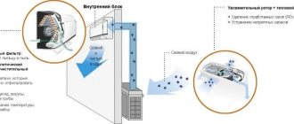
A dielectric coupling is a cut-off fitting that protects the “brains” of gas-consuming devices from the destructive effects of stray currents. That is, we have before us a very useful unit, the effectiveness of which has been proven by the definition itself. However, many owners of gas stoves, water heaters and boilers, as well as employees of gas services, do not know about the existence of such an insert. And in this material we will try to eliminate this gap in knowledge by talking about the benefits of dielectric fittings, its varieties and installation methods.
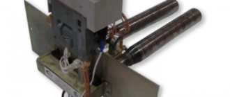
Dielectric insert device for gas
To cut off stray currents, polymer inserts for gas pipes are used. A
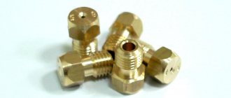
dielectric coupling or insert for gas is a cut-off type fitting, which is placed on the element between the tap and the supply part to the gas unit. This element is divided into two categories based on its appearance and installation method. Simple inserts are attached between the gas supply device and a hose suitable for a specific system; more modern bushings are mounted at the junction of pipe parts.
Such couplings vary in size, varying depending on the thread diameter; parts with numbers 1/2, 3/4 and 1 are most often used. The presence of several element options allows you to select a product for a specific size of flexible bellows liner. The thread of the coupling can be internal or external. The bushings and inserts have identical parameters regarding strength and can withstand pressure up to 6 atmospheres.
Most often, the insulating insert on any gas pipeline is made of polyamide; this material belongs to the category of non-flammable polymers, its resistance varies within 5 million ohms.
Preparing pipes for insulation
The gas pipeline fragments listed above that require additional thermal insulation can be steel or polyethylene - therefore, the most suitable materials for insulating such pipes must be selected. It is better to wrap PE pipes with elastic sheet or tape material, and metal pipes with a heating cable or place them inside a PP shell.
In any case, the gas pipeline must be prepared before insulation. The recommended air temperature for installation work is +10 °C, so it is better to postpone the event until the warm season.
The insulated surface must be thoroughly cleaned of dust, dirt, grease, and adhering street debris. We recommend using a special cleaner-diluent based on ethyl acetate. If you plan to glue the thermal insulation onto a painted surface, you should ensure that there is sufficient adhesion.
Useful tips that will come in handy during the installation of pipe insulation:
- if you plan to use insulating tees, corners, bends, get ready to fix them first, and then insulate the straight sections;
- expect that glue, if used, will have to be applied both to the surface and to the insulation, and when gluing the ends - both to the ends and about 2 cm to the inner surface of the insulation;
- stretch the insulation during installation, taking into account the linear expansion of the pipes;
- To give a holistic appearance, place all seams on the wall side.
We recommend preparing a set of tools in advance: glue brush, stationery knife, compass, scissors, punches, miter box, ruler, tape measure, marker. A spatula is useful for puttying work.
Before attaching the self-regulating cable, the steel pipe is also coated with protective paint in 2 layers and grounded.
Causes of leakage currents
Stray currents cause the formation of fistulas on metal pipes
Stray currents are usually formed underground due to impulsive breakdowns of household or factory power lines. The source of voltage in such cases becomes the grounding loop, railway or tram tracks. This type of current enters the gas pipeline system due to differences between the resistance of the soil and metal particles from the fuel supply line. As a result, the entire volume of electricity that gets into the ground does not go inside it, but goes into metal elements or bare wires. Current can be generated within the system at any time, since most household or public gas pipelines are made of metal.
Often the cause of stray voltage is the main pipe. To protect the pipeline from rust, it is loaded with electrical potential with a slight force. It blocks the process of electrochemical separation within structural materials. If the dielectric coupling for gas in a single insulator is damaged, the good protection potential turns into excess current. In addition, such voltage can arise due to poor grounding of circulation pumps or other parts that come into contact with the heating system wiring or home pipeline branch.
A dielectric for gas flows can eliminate serious problems and increase the level of safety for everyone who uses gas equipment that is connected to the general system.
Many people say that it is not needed
There are several opinions about these couplings.
It is not needed because the currents are not that strong and they will not do anything to the electronics. This is not entirely true, the currents may be small, but they are extremely undesirable for control boards. I repeat AGAIN, modern two-circuit boilers have a bunch of electronics, and they can often suffer from this. This happened, for example, on BOSCH boilers. There, it was precisely from jumps and stray currents that the main board burned out, and it is very expensive.
- The outlet is grounded, so a dielectric coupling is not needed. Grounding is good, but as practice shows, it does not save so much from stray currents
- You can put a plastic gas hose or PVC pipe up to the boiler. It is possible, but as practice shows, such connections are less durable than metal ones.
- It costs expensive. This is the kind of nonsense, the most expensive one I have seen is the price of about 300 rubles. And prices start at about 95 rubles. Compared to the gas device and heating system, these are just mere pennies
Therefore, I strongly recommend that you install this device, it costs a penny, and it works effectively.
Applications and functions of dielectric inserts
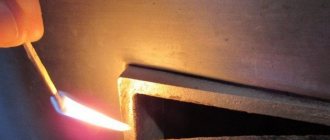
The absence of a dielectric insert can lead to a spark and gas detonation.
The gas dielectric coupling is a mandatory element, the presence of which is provided for by the rules governing the construction of gas distribution systems SP 42-101-2003. It must be present in pipelines of any type, including options with polyethylene pipes. If there is no such coupling, the stove, column or other electrical appliances can fail at any time after the appearance of stray current or become its cause. Sparks may occur inside the pipeline and cause a fire. Cases of spontaneous ignition of wiring occur quite often and can cause a major accident.
The process of detonation of the gas-air mixture may well destroy a multi-story building when the fire is not detected in time. When stray current appears inside pipes due to an emergency or during a thunderstorm, the risk of serious injury to owners of electrical appliances increases significantly. A dielectric coupling for each gas pipe must be installed in any building or apartment where gas-powered appliances connected to electricity are operated. In addition to its main functions, it prevents the formation of stray currents that arise due to problems during the installation of boilers, water heaters or gas stoves.
How to properly connect a gas stove
Gas stoves in our kitchens, despite their undeniable advantages, have always been, are and will remain a source of increased danger.
Even such modern modifications to the “hearth” as gas flow control or an automatic ignition system will not save the situation in case of installation errors.
Each owner needs to study information on how to properly connect a gas stove, since he will have to collect a package of documents and draw up an agreement with the gas supplier himself.
Despite the apparent simplicity of the work, it is strictly forbidden to carry out the initial connection of the gas model of the stove with your own hands. At best, such actions will entail a fine; at worst, the consequences may be dire.
Sequence of actions when connecting the device
Before carrying out work on installing the stove, it is necessary to go through some bureaucratic procedures at the gas service of your area: conclude an agreement for the supply of gas to the apartment and open a personal account.
What documents need to be provided to connect a gas stove in an apartment:
- owner's passport;
- certificate of state registration of residential premises or the right of ownership (sale/donation agreement);
- technical passport for the apartment;
- certificate of family composition;
- maintenance contract;
- passport for gas flow meter;
- subscription book (if the stove is being replaced with a new one).
The prepared documentation is checked by specialists, who then issue the following forms to fill out:
- Application for concluding a gas supply agreement for municipal and domestic needs.
- The contract itself, which specifies the characteristics of the equipment, monthly gas consumption rates and determination of its volume (depending on the combination of devices), the term and form of payment, as well as the frequency and procedure of inspections.
- Subscriber book containing information about the service organization, full name and address of the subscriber, type and name of installed equipment, operating rules for gas appliances, a note on training with all family members, work plan and date of the next inspection.
USEFUL INFORMATION: Calculation of kitchen hood power
As a result of signing the contract, the gas service issues permission to install the stove in the apartment.
Information on where to go to install a new stove to replace the old one and how much it will cost can be found here. Read about the possibility of free replacement of a kitchen appliance in this article.
note
After completing the necessary administrative procedures, the question arises as to whether it is possible to connect the gas stove yourself. The answer to this is clear: you can carry out such work yourself only if you replace the household appliance with an equivalent one, without interfering with the design of the connection to the gas pipeline.
In all other cases (if you need to check/replace a hose or tap, move a stove, etc.), you should contact the gas workers of a service organization or a company specializing in such services.
Preparing to connect
Despite the fact that it is prohibited to connect the stove with your own hands, you need to familiarize yourself with the requirements and instructions for this type of work in order to prepare the kitchen area and the necessary materials.
When connecting the device, the following prerequisites must be met:
- Availability of high-quality natural and forced (exhaust) ventilation.
- The distance from the gas pipeline pipe to the stove should not exceed 4 meters, ideally up to 2.
- Since modern devices are equipped with oven lighting and an automatic ignition system, an electrical outlet with grounding must be provided at the stove.
Currently, combination stoves are very popular, i.e. gas burners and an electric oven combined in one device. If this is your case, then it is necessary in advance (at the repair stage) to supply electricity through a separate power line from the distribution board, using a 3 × 1.5 cable and an additional 16 A RCD.
USEFUL INFORMATION: Membrane water filters: types and principle of operation
Necessary materials
As a rule, craftsmen who connect gas stoves have with them all the tools required for the job. But high-quality materials and devices (which are needed for replacement and installation) will have to be prepared in advance yourself.
Hose
Currently, the standard for connecting a gas stove model requires the use of a flexible hose, available in three types: rubber-fabric, rubber with metal braid, and bellows.
GOST R52209-2004 recommends the use of a bellows gas hose, which is a stretchable steel hose in a protective sheath. This model is by far the strongest and most reliable, but also the most expensive.
Dielectric insert
If the device is connected using a rubber hose with a metal braid, be sure to use a dielectric insert, which is located between the valve on the lower side and the hose. This simple device prevents the transmission of stray currents through the metal braid from the gas riser to the stove.
Ball valve
In most cases, a petal valve is initially installed at the lower end of the gas pipe, which is recommended to be immediately replaced with a ball valve. This type of locking device has a simpler and more reliable design.
Sealant
It is quite possible that a sealant for sealing joints is included in the installer’s tool kit, but in order to be sure of the quality of the material, it is worth keeping your own on hand. You can take FUM tape or anaerobic sealant.
Thus, after studying the information on how to properly connect a new gas stove, as well as purchasing all the necessary accessories and materials, everything is ready for the visit of a gas technician.
We recommend watching a training video about the rules for connecting the stove.
Source: https://mr-build.ru/organizatsiya-remonta/podklyuchenie-gazovoj-plity.html
Types of dielectric inserts for gas
The dielectric for a gas hose, according to the product range of elements for gas distribution devices, is divided into two standard categories. These are insulating taps, couplings, barrels or bends, as well as standard bushings. The choice of a specific type depends on the installation conditions and the characteristics of a particular system.
Insulating couplings
Insulating coupling made of dielectric material
Couplings are divided into three categories, which differ from each other mainly by their threaded diameter; its value can be 15, 20 or 25 mm. Separation according to this criterion makes it possible to install inserts in any pipelines, since the Russian gas pipeline system does not use diameters smaller than 1/2 and larger than 1/4. Subtypes of inserts, so-called barrels, can have external threads on both elements or internal and external threads on each.
Dielectric bushings
Such inserts are liners that prevent the passage of electric current. They are placed between gas pipes and wiring, the diameter of such elements ranges from 8-27 mm, both sides are threaded from the inside. Bushings are not inferior to couplings in terms of resistance and strength; parts can withstand pressure up to 493 atmospheres.
Gaseous dielectrics
The main gaseous dielectrics used in electrical engineering are: air, nitrogen, hydrogen and SF6 gas (sulfur hexafluoride).
Compared to liquid and solid dielectrics, gases have low dielectric constants and high resistivity and reduced electrical strength.
The properties of gases in relation to the properties of air (in relative units) are given in the table.
Properties of gases in relation to the properties of air
Nitrogen is used as insulation in capacitors, high-voltage cables and power transformers.
Hydrogen has a lower electrical strength compared to nitrogen and is used mainly for cooling electrical machines. Replacing air with hydrogen leads to a significant improvement in cooling, since the thermal conductivity of hydrogen is much higher than that of air. In addition, when using hydrogen, power losses due to friction with gas and ventilation are reduced. Therefore, hydrogen cooling makes it possible to increase both the power and efficiency of an electric machine.
SF6 gas is the most widely used in sealed installations. It is used in gas-filled cables, voltage dividers, capacitors, transformers and high-voltage circuit breakers.
The advantages of a cable filled with SF6 gas are low electrical capacitance, that is, reduced losses, good cooling, and a relatively simple design. Such a cable is a steel pipe filled with SF6 gas, in which a conductive core is reinforced using electrical insulating spacers.
Filling transformers with SF6 gas makes them explosion-proof.
SF6 gas is used in high-voltage circuit breakers - SF6 circuit breakers - as it has high arc-extinguishing properties.
Correct installation
Installing a dielectric insert into a gas pipe
An insulating coupling or insert for gas must be inserted between the gas tap and the bellows or other type of connection. It is necessary to install the element taking into account safety requirements; before starting the installation, you will need to turn off the tap and do not open it until all the necessary actions have been taken to eliminate possible leaks. Installation must be carried out by gas service employees who have the appropriate qualifications and permission to perform this type of work. During installation you will need:
- Prepare a pair of adjustable wrenches, one of them is designed to hold the body from the valve, the second one needs to tighten the nut from the liner connecting the tube to the device running on gas fuel.
- Install any type of sealant, for example, polymer, on the ends of the insert, then place the dielectric inside the gas pipeline manually.
- Holding the valve with one key, tighten the second coupling or bushing until it stops; during the installation process, you need to be careful not to accidentally tear off the threaded coating and damage the body of the element.
- Screw the nut from the bellows-type hose to the other part of the coupling, while holding the insert with an adjustable wrench, and then tighten the connecting parts as tightly as possible.
When the standard gas dielectric is installed, you will need to check the joining areas for the level of tightness. For this purpose, use a small brush or brush, which is thoroughly soaped. The soap solution must be applied to each inlet, as well as the joint, then slowly open the gas tap. If there is foam or bubbles, turn off the tap and re-inspect the joint areas. It is possible to use the gas unit only after bubbles stop forming in the solution. In no case should the leak be checked using matches or a lighter; if there is a leak, fire may cause a gas explosion.
Connecting equipment to a gas pipe using a dielectric insert
The installation of gas units and additional components is carried out with particular precision, since the safety of the building’s occupants directly depends on the correct connection of the parts. The hoses are installed according to the principle of open installation; the hoses should not be hidden or covered with furniture or household appliances; the element itself, as well as the dielectric bushing or gas coupling, must be mounted from the outside. To connect the equipment, do not use hoses that are too long or shortened, since due to pressure this part may become shorter; in addition, it is forbidden to stretch it. The hose may sag after joining the pipe, but it must not be twisted or kinked.
When installing a dielectric adapter for household gas, you need to make sure that the hose does not get steam or water, which can provoke oxidation of metal parts. Cooking surfaces are placed away from the gas pipeline pipes; if there are atypical threads in the stoves and other equipment, adapters are used for connection.
You should not combine different materials, for example, steel and copper. You also need to monitor the pressure on the element while tightening the connections so as not to spoil or tear off the threaded coating. To ensure a tighter fit, be sure to use FUM tape.
The need to install insulating connections for the gas pipeline
Stray currents pose a high danger to equipment, personnel and the gas pipeline itself. The main problem is that the section of the gas pipeline exposed to stray currents is impossible or extremely difficult to calculate in advance. Such impacts create the preconditions for the occurrence of destructive processes and disrupt the operation of control and measuring instruments.
An insulating connection (IC) for a gas pipeline allows you to separate sections from each other and prevent the occurrence of electrochemical corrosion. It ensures breaks in the galvanic connection of gas pipeline sections and eliminates the possibility of initiating corrosion processes.
Diagram of an insulating connection on a gas pipeline
ICs cut off grounded areas from the common branch that are in contact with adjacent equipment or structural elements. The gas pipeline IC increases the resistance between sections to values that prevent further propagation of currents along the length of the gas pipeline.
Most often, the protective device takes the form of flange connections equipped with a dielectric gasket.
It is allowed to use only units manufactured at specialized enterprises and having the appropriate certificates.
It should be taken into account that the use of an insulating connection is a mandatory clause of the technical regulations, the violation of which entails various consequences, including criminal prosecution.
What are the types of insulating connections?
The most commonly used types of insulation are:
- flanged;
- one-piece;
- insulating rings made of paronite.
Types of insulating connections
The most common type is the insulating flange connection. The design of such a unit is quite simple and reliable. It does not consist of 2 flanges, as usual, but of three - there is an average intermediate flange 16-20 mm thick.
Isolating flange connection diagram
Insulating rings made of paronite are installed between the flanges, which, in order to avoid impregnation with water and loss of dielectric properties, are coated with a special bakelite varnish.
The tie is made with steel pins installed in fluoroplastic dielectric split bushings. A more modern insulation option is permanent connections, such as an insulating coupling.
Advice
They are presented in various design options, different sizes, but have common specific qualities.
The most important of them should be considered the high durability of such ICs. They do not require maintenance and do not change their properties over time, whereas the insulating flange connection gradually loses its dielectric properties and requires restoration work.
Conditions for using IP
Gas pipeline ICs are used in accordance with the electrical protection plan and are installed in compliance with all safety measures. At the same time, the protection should not have a harmful effect on adjacent structures: it is necessary to exclude the formation of electrochemical corrosion on adjacent elements of the system that previously did not require protection.
The optimal points for installing the gas pipeline IC are:
- Entry or exit from the ground.
- Entrance or exit from a gas distribution point.
- Entry into an industrial facility (enterprise).
- Entry into a building with the possibility of contact with grounded elements.
- Inserting a gas pipeline into an object that is a source of stray currents.
- At gas pipeline branches, an IS is installed for each branch.
The use of IS is prohibited on open sections installed under balconies or doorways. In wells, the protection is bridged with a detachable electrical jumper. On above-ground sections of gas pipelines, it is necessary to install insulating connections at the entrances to buildings, on supports, overpasses or bridges. The use of insulation makes it possible to reduce the current density of electrochemical protection by 1.5–2 times.
Installation rules
The assembly of protection units is carried out in the factory. When installing a unit on an existing gas pipeline, all safety requirements and technical rules for working with gas installations must be observed.
Insulating insert
The finished assembly is tested for resistance and tightness in the laboratory, about which a corresponding record is made.
Installation is carried out by welding, after which the quality of electrical separation of the sections is checked.
The evaluation criterion is the value of electrical resistance, which must be at least 5 ohms and provide a voltage drop of at least 5 mV when measured at different ends of the flanges.
The finished connection is isolated from possible contact with the ground or structural elements using aprons, boxes or similar means.
Acceptance of an insulating connection into operation is documented by a corresponding entry in the journal and a certificate.
Benefits of support rings
Support rings, like any other product, have their own advantages. The main advantages of this device include:
- friction indicators when using these polymer devices are reduced to a minimum, so they are considered very reliable;
- thanks to the first point, the protective coating of the pipeline is not damaged during the process of pulling it through the case;
- the speed of installation work is quite high, which reduces the cost of building a highway;
- such supports make it possible to extend the service life of communications as a whole, since contact between pipes is eliminated and the corrosive effect is reduced;
- the supply pipe can be removed if such a need arises;
- the transverse ribs that make up this support may differ in size. This allows internal communication to be carried out in the center of a protective case of any diameter;
- polypropylene is a reliable insulating material and provides reliable cathodic protection of the pipeline.
Preparing pipes for insulation
The gas pipeline fragments listed above that require additional thermal insulation can be steel or polyethylene - therefore, the most suitable materials for insulating such pipes must be selected. It is better to wrap PE pipes with elastic sheet or tape material, and metal pipes with a heating cable or place them inside a PP shell.
In any case, the gas pipeline must be prepared before insulation. The recommended air temperature for installation work is +10 °C, so it is better to postpone the event until the warm season.
The insulated surface must be thoroughly cleaned of dust, dirt, grease, and adhering street debris. We recommend using a special cleaner-diluent based on ethyl acetate. If you plan to glue the thermal insulation onto a painted surface, you should ensure that there is sufficient adhesion.
Useful tips that will come in handy during the installation of pipe insulation:
- if you plan to use insulating tees, corners, bends, get ready to fix them first, and then insulate the straight sections;
- expect that glue, if used, will have to be applied both to the surface and to the insulation, and when gluing the ends - both to the ends and about 2 cm to the inner surface of the insulation;
- stretch the insulation during installation, taking into account the linear expansion of the pipes;
- To give a holistic appearance, place all seams on the wall side.
We recommend preparing a set of tools in advance: glue brush, stationery knife, compass, scissors, punches, miter box, ruler, tape measure, marker. A spatula is useful for puttying work.
Before attaching the self-regulating cable, the steel pipe is also coated with protective paint in 2 layers and grounded.
Features of support and guide products
Conventional pipeline supports perform a number of functions. Their main “duty” is to fix the structure. In addition, thanks to the sliding supports, linear expansion of the pipeline has no consequences. And the support-guide rings allow the internal pipeline to be pulled through the outer communication part (case) without causing any harm to it.
Based on this, we can identify several main functions that are carried out thanks to just such a support:
- protection of the pipeline from various damages;
- protection of coupling joints and welds;
- simple and quick pulling of the pipeline through the case;
- support for the supply pipe;
- cathodic protection against corrosion (thanks to this detail, the possibility of contact between the metal frames of two pipes is eliminated).
Installation of these rings is carried out at the assembly stage of the pipeline itself. Their installation does not require the use of special equipment, since the support ring is fixed using electric arc welding. The most common materials for such supports are high-quality polypropylene and steel.
The design feature of the supports makes it easier and faster to pull the inner pipe into the outer one
Fluoroplastic tapes (FUM)
FUM tape, or fluoroplastic sealing material, is a unique product that is widely used in the construction of gas supply, water supply, heating and sewerage systems. Fluoroplastic is very strong and flexible, has a high melting point (about +400 degrees), is resistant to oxygen, aggressive liquids, and low temperatures (withstands up to –70 degrees).
PTFE tape or thread is not wetted by solvents, fats, or water. Remaining dry and durable, it can withstand increased pressure in the system. The material fills all the unevenness of the thread, reliably sealing it and sealing the joint. Stores sell threads with a diameter of 0.4–1.5 mm and ribbons with a width of 1–1.6 cm, so you can easily choose the appropriate option.
The material does not tolerate only regular and strong vibration: the connection loses strength, its tightness is broken. To improve the technical characteristics of the seam, FUM should be used in conjunction with silicone pastes or sealants.
FUM tape is wound in the same way as flax: along the thread with an increase in layer from the end of the pipe. The required number of turns is determined in each case individually and depends on the gap in the connection. Usually the thread is wrapped so that its relief becomes almost invisible, and serious force is applied during assembly.
Bitumen VUS
Very reinforced bitumen insulation is used as waterproofing and a way to prevent corrosion on steel pipe lines in non-channel types of laying water supply lines and industrial pipelines.
The main area of use of existing coatings is the prevention of corrosive formations in a network of small-diameter pipes that operate at normal temperatures.
The multilayer structure of bitumen-mastic treatment consists of:
- primer on the surface of the pipes;
- the first layer is reinforced fiberglass;
- the second layer consists of bitumen mastic, which consists of hydrophobic materials;
- the next reinforcing layer consists of fiberglass;
- a pair or a single layer of coating consisting of kraft paper.
Video
Very reinforced bitumen-polymer insulation has the following advantages:
- Easy to apply.
- Great level of durability.
- Resistance to mechanical damage.
- Resistant to cathodic disbondment.
- Excellent adhesion characteristics to steel parts.
- Minimum oxygen and water permeability.
- Resistance to corrosion formations.
- Tolerance to temperature changes.
Universal sealing thread
Universal threads are an improved version of FUM tapes and are made from more modern materials. Usually these are nylon impregnated with sealant, polyamide with silicone. They can be used in pipes supplying natural gas, compressed air, as well as in water supply and sewerage systems, including on wet threads and at sub-zero air temperatures.
The most popular brands of threads are:
Such threads are considered universal due to their ability to be used on metal and plastic, which is very important for modern gas pipeline systems. For these materials, the condition of the pipes is not important - they may even be rusty, old, or damaged.
After winding, the impregnated thread undergoes instant polymerization, and the connection can be put into operation immediately, without waiting time. This makes multi-purpose threads suitable for emergency repairs and emergencies.
Control tube
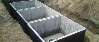
The control tubes are lowered with their free end into the tank to different depths and end at levels corresponding to the controlled volumes. Shut-off needle valves are screwed onto the outer ends of the tubes, the opening of which determines from the exiting gas stream whether it is gas or liquid. To reduce the risk of being struck by a gas stream, a throttle with a diameter of 3 mm is installed in front of the valve. When opening valves to check the level of liquefied gas, operating personnel must always wear gloves on their hands and stand to the side of the valve outlet fitting to prevent the escaping gas stream from hitting the operator, especially exposed, unprotected parts of his body. In cases where the evaporation capacity of the tanks is insufficient to supply gas to consumers, piping the tanks with evaporation units is used.
| Relief safety valve. |
The control tubes are lowered with their free end into the tank to various depths to the levels of the controlled media.
Control tubes are more effective on a gas pipeline that is located above the groundwater level. In some cases, devices are installed that block the gas from leaking into the danger zone and make it easier to detect. A loosened strip of earth allows gas to escape as it spreads from the leak point towards basements and buildings. To control leaks and remove gas in the desired direction, in some cases permanently open drains, similar to control tubes, are installed.
The control tube is a U-shaped tube filled with soda lime and calcium chloride in approximately equal quantities. The layers of calcium chloride and soda lime should be separated at the bottom with a small piece of cotton wool (Fig. 45), and at the top they should not reach 6 mm to the side outlet tubes; they are covered with pieces of cotton wool on top; The tube is closed with stoppers and filled with Mendeleev's putty. Rubber tubes covered with scraps of glass rods are also placed on the side tubes.
| Main characteristics of safety relief valves. |
The control tube (Fig. VI-33) is made of a steel pipe with a diameter of 2, the lower end of which is welded to a casing made of sheet steel 2 - 3 mm thick and 350 mm wide, bent in the form of a semicircle and usually placed above the joint of the gas pipeline. The space between the casing and the gas pipeline is filled with a layer of crushed stone or gravel. The upper end of the control tube is equipped with a stopper, brought to the surface of the earth and protected by KB-ver.
| Control tube device. |
Inspection tubes are of great importance for correct operational supervision; They are the main device that makes it possible to check the density of a gas pipeline from the surface of the earth.
Control tubes can only conditionally be classified as devices that protect underground gas networks from damage. Their main task is not to protect, but to create conditions that allow timely detection of a gas leak from a pipe, take urgent measures to protect the gas pipeline from further damage, as well as eliminate possible consequences of the leak.
Control tubes are installed along the gas pipeline route at certain distances, as well as above points in the gas pipeline for which it is desirable to carry out systematic operational supervision.
| Control device Installation for suction and tubing of gas from the ground. |
Inspection tubes are of great importance for correct operational supervision; They are the main device that makes it possible to check the density of a gas pipeline from the surface of the earth.
Control tubes are brought to the surface of the earth under the carpet in accordance with the requirements of 2 - 1 - 5 of these Rules.
| Reservoir head. |