In order for grounding to function properly, the resistance of its conductors should not be higher than 4 Ohms, and it is necessary to regularly monitor that this indicator does not increase. Next, we'll figure out how to test the grounding to determine whether the protection is capable of functioning effectively. Let's consider what instruments are needed for this, how often it is necessary to check, and what minimum theoretical knowledge is needed for this work.
Measuring ground loop resistance Source gradusplus.com
Basics of functioning of grounding systems
Potential may accumulate on the housings of some electrical devices (with high conductivity, for example, metal) due to the ingress of current in the event of a breakdown of the insulating layer of the wiring. If there is such a malfunction, any touch to the body of the device is fraught with the passage of current from the device to the “ground” through the person (from the hand and then along the body and leg to the “ground”). Under unfavorable circumstances, this can lead to death, because Only 100 mA is enough for the damaging processes from an electric shock in the human body to lead to irreversible consequences.
As you know, electric current tends to pass through conductors with the lowest resistance. This property serves as the basis for the functioning of any protective grounding system. In essence, grounding is the connection of metal parts of electrical installations with a conductor of maximum capacity and minimum resistance, which reliably protects a person from electric shock if it hits the device body.
The human body, consisting mainly of water, is considered a good conductor with a nominal resistance of 1000 Ohms. Calculations show that electric current will “pass by” a person if it flows through a conductor with a significantly lower resistance, which does not exceed 4 Ohms and 8 Ohms - at a voltage in the circuit of 380V and 220V, respectively. It is these values that are indicated in the PUE and you need to focus on them.
Regular testing and measuring of grounding, discussed below, can prevent possible negative consequences in advance.
Schematic representation of the grounding system for almost any household appliance Source gradusplus.com
The power cable of any modern electrical device contains a special wire that connects the device body to a separate contact on the plug. When this plug is inserted into an outlet, this pin makes contact with the grounding terminal of the outlet, and therefore with the entire grounding of the structure.
If, due to damage to the wiring, an electric current leaks, the latter will go into the ground through the grounding wiring, which has minimal resistance. For this protection to work properly, resistance indicators are of key importance, monitoring which makes it possible to prevent and prevent possible accidents.
Disconnecting wires in the panel
This method can be used in any power supply circuit, and to implement it, a voltage indicator with two probes, even the old Soviet PIN-90, is sufficient:
- 1. the input circuit breaker in the electrical panel is turned off;
- 2. the wires are disconnected from the grounding bus;
- 3. the circuit breaker turns on;
- 4. In the distribution or installation box, the indicator searches for two conductors, the voltage between which will be 220V.
The remaining conductor is the grounding conductor.
The need for regular checks
The need to maintain the serviceability of the ground loop is considered a prerequisite for the effective functioning of the system. Therefore, a periodic grounding test with a multimeter (as the most accessible tester for the average person) is needed, the results of which will determine the performance of the circuit.
If the grounding is in normal working order, any emergency situation that arises will lead to the discharge of electric current through the grounding conductor into current-carrying elements located in the ground, from which the electric discharge will quickly and uniformly spread deep into the soil.
Grounding diagram for a private house Source sovet-ingenera.com
See also: Catalog of companies that specialize in electrical work of any complexity
The reliability of any electrical circuit is inversely proportional to the number of conductor connections - the fewer, the better. But in any case, it is impossible to get rid of them completely. In addition, it must be taken into account that some of the connections are in the ground and from prolonged contact with it, an oxide layer is formed on the metal of the current-carrying electrodes, leading to the inevitable formation of a corrosion layer.
The result may be an increase in the resistance of the device elements and the occurrence of obstacles to the flow of current. Plus, the presence of any substance with increased chemical activity in the area of soil that includes grounding leads to the fastest possible occurrence of rust, since the metal parts of the circuit constantly interact with the soil.
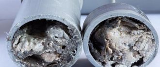
Over time, corrosion leads to the formation of individual flakes that begin the process of peeling away from the metal, thereby deteriorating the electrical contact. Because of this, the circuit resistance increases, because the number of these corroded areas becomes large. The grounding device loses electrical conductivity, the likelihood of incomplete discharge of electric currents into the soil increases, and the overall level of protection decreases.
As a result, the inspection usually begins with an assessment of the technical condition of the circuit and its components.
An example of corrosion of a grounding device Source gidpokraske.ru
Measuring the ground loop resistance makes it possible to verify the safety of the system. Technically, this calculation of resistance is based on Ohm’s law, known to everyone from the school physics course. If the voltage and current in the current source are known, or we can measure it, then it is enough to simply determine the resistance by dividing the voltage by the current. But the practice is somewhat more complicated and has a number of features and measurement rules that require their strict implementation.
Clamp meter
If all devices are connected correctly, and you need to find a grounding wire in the junction box, for example, to connect an additional line, you can use a current clamp. This device allows you to measure the current flowing through a wire without cutting it.
To do this, you need to turn on the electrical appliances connected after the box and measure the current in the wires. Since power is supplied through the neutral and phase conductors, there will be no current in the grounding wire.
Professional measurement (using a megohmmeter)
The generally accepted grounding measurement includes the following sequence of actions:
- Visual inspection of connections on bolts and welded contacts should be carried out;
- take resistance readings of the entire circuit;
- check the resistivity of the soil layer.
Measurements are carried out using special instruments. The megohmmeter that is best suited for this is considered optimal.
Megaohmmeter – model M-416 Source pribor-service.ru
Types of electrical outlets
The industry produces two types of products:
- equipped with a grounding bus;
- not having a grounding bus.
The first type of design is often called a “euro-socket”. This design fully satisfies electrical safety requirements. When changing electrical wiring, it is recommended to install sockets with grounding.
The appearance of the electrical outlet according to the standards established by the European Union countries. A distinctive feature of the design is the presence of contact bimetallic grounding plates
The second type of product is considered an outdated modification, but is still found in practice. Especially many outdated sockets are used in old buildings.
Design option without specific country affiliation. For modern electricians, it is considered an outdated model, which is not recommended for installation due to increased danger due to the lack of a grounding contactor
Both types of products are made for indoor or outdoor installation. According to the new PEB recommendations, modifications of sockets for internal installation must have bimetallic plates with a grounding contactor as part of the design.
For electrical sockets for external installation, the recommendations are the same, but in some cases of their use a two-wire interface is allowed.
Video description
Briefly about the theory and practice of using ohmmeters M-416 and M-4001 is described in this video:
- The rod of the probe and the accessory electrode are driven into the soil to a depth of over half a meter. This is done on soil with natural density (not poured or loosened) by hammering it in with a sledgehammer.
- At the junction of the grounding wire and the electrode, it is important to clean off the remaining paint coating. Copper wires with a cross-sectional area of 1.5 mm² are used.
- It is recommended to begin direct work on measuring the resistance of protective devices by selecting the “x1” range. After pressing the red button, the handle of the device rotates until the arrow reaches the zero mark. Higher resistance values should be measured by choosing larger ranges - “x5” or “x20”. For measuring the resistance of the protective circuit, the indicator “x1” is used, which is sufficient to display the results on the instrument scale.
It is optimal to carry out such measurements in the most dense soil and in dry summer weather conditions. You can make the same measurements in winter, but it is recommended to do this during frosts, when the soil is frozen as much as possible. It is not advisable to take measurements in wet weather, because... the data obtained will be greatly distorted and therefore unreliable.
Checking grounding with an electronic megohmmeter Source uk-parkovaya.ru
Typical socket design
Using the socket grounding test technique may be necessary at any time. Especially for those people who will have to work with specific electrical outlets repeatedly.
This part of the electrical network (domestic or industrial) has a simple design.
The electrical outlet does not shine with design difficulties. A simple ceramic or plastic base plus a metal frame with a lid. Still, electrical outlets are improving.
The electrical outlet consists of a round or rectangular plate. The plateau is made from materials that do not conduct electricity.
Typically, the following is used to make socket plates:
- ceramics;
- porcelain;
- plastic.
The back of the plateau has a flat surface, and on the front there are shaped landing pads for electrical contactors. The material of contactors is usually copper. The contactors are fixed to the plateau rigidly - using rivets, plus they are embedded in the body of the plateau.
For connection to electrical wiring, the contactors have mounting screws. This entire structure is closed with a lid that has two passage holes for an electrical plug.
Checking grounding in a home network (using a multimeter)
As a rule, in new housing, the electrical network has already been wired, so you need to know how to check the grounding resistance of already installed household outlets.
This work should also begin with a visual inspection of the item being measured. You should turn off the power and remove the protective cover of any of the sockets that are equipped with a special terminal for connecting the ground loop conductor (usually a yellow-green wire). If only two wires are connected to the contacts (phase and neutral, usually brown and blue, respectively), then this clearly indicates the absence of grounding.
If the third wire is still present, this does not guarantee its proper functioning. It is necessary to carry out a special test procedure with a multimeter. The sequence is as follows:
- The input circuit breaker is turned on so that there is voltage in the network (sockets).
- The tester switches to voltage measurement mode - usually this is the “ACV” icon.
Wire color coding
The color of the cable sheath is not chosen arbitrarily, but according to certain rules specified in GOST 31947-2012 clause 5.2.1.6. If you are confident that these rules were followed during installation, the easiest way to find out the purpose of the conductor is to determine it by the color of the insulation:
- brown, black or gray - phase (L);
- blue - neutral (N);
- longitudinal yellow and green stripes - grounding (PE).
This method is applicable for electrical wiring completed after 2012.
Video description
This short video shows how to check the grounding of a socket using a multimeter:
- The probes of the device are applied to the contacts, and the voltage between the phase and neutral wires is measured. For a home network it should be standard 220V.
- Similar measurements are made with a multimeter with phase and ground - the result should be approximately the same as in the previous measurement. If the instrument scale shows a lower voltage reading, it means the grounding is not working well. If the device does not respond when the probes touch the contacts, it means that the ground loop is not connected or is faulty.
Even when there are no measuring instruments in the house, it is possible to check using available means. You will need a homemade device in the form of a light bulb screwed into a socket, from which extend pieces of wire with stripped contacts at the ends. People call it “control”. Such a device is sometimes used by self-taught electricians (and not only), but, as a rule, its use is not recommended by professionals.
To check, one contact of the “tester” is in contact with the phase, and the second is in contact with zero. When the light comes on, it indicates the presence of voltage. Then the contact from zero is moved to the ground wire. The operation of the light indicates the presence of a working protective system. A weak or intermittent glow indicates problems in the circuit, and a complete absence of light indicates its complete malfunction.
Appearance of the panel of the most common electronic multimeter with explanations for use Source lifehacker.ru
What to consider
When using outdoor lighting on metal supports, grounding plays a key role in ensuring the safe operation of lamps. And this part of the PUE is regulated. When installing external lighting, you need to rely on the following points of the PUE:
Grounding the luminaire
- on all types of lamps used in outdoor lighting systems, protective grounding is mandatory and there are no exceptions;
- Grounding is organized using special grounding devices. These devices are designed for re-grounding, as well as protection against lightning surges and grounding of electrical equipment (luminaires) that will be mined on supports;
- the resistance that the grounding device must have is no more than 30 Ohms;
- Protective grounding for metal housings of local lighting lamps with voltages above 50 V involves the use of protective conductors. They are attached to the metal structure on which the lamp was installed. And a reliable electrical connection must be created for the bracket and the housing;
- for lamps, as well as for supports, grounding against atmospheric voltage is necessary;
- the total spreading resistance for grounding conductors (of any type) using reused PEN conductors should be within the range of no more than 5, 10 and 20 Ohms (depending on the line voltage).
PUE standards are developed for different situations, but have more or less universal application.
Briefly about the main thing
The resistance of a properly functioning grounding should be 4 Ohms. Since the resistance at the conductor connections may increase over time, the grounding must be checked regularly - approximately every 12 months.
There are several ways to measure the grounding resistance of a home network. Professionals carry out this work using a device such as a megohmmeter. At home, you can use a standard multimeter or even a homemade “control”, but you need some experience to correctly interpret their readings.
In general, tests are based on Ohm's law - the voltage in the circuit and the current are checked and the resistance is calculated from them. The measurement procedure is quite simple and can be done by the average person if he knows the basics of working with electricity and electrical safety rules. If you have doubts about your skills, it is recommended to seek the services of specialists.
Differential current (RCD, difavtomat)
Another option for distinguishing zero from grounding involves the presence of differential protection in the panel with a setting of 10-30 mA. These devices compare the current flowing through the neutral and phase wires and turn off if the equality is violated.
To search for a grounding conductor, an electrical appliance, for example, a lamp with a power of more than 10 W, must be connected to the cable being tested. If the protection is triggered when turned on, it means that grounding is used instead of the neutral wire.
| Important! Before starting work, you must check the serviceability of the RCD by pressing the “TEST” button. |
How to make grounding at the dacha
The best option for grounding a dacha would be a triangle, in which there are steel electrodes at the top, extending into the ground at least one and a half meters. The contour should be at a level where the ground does not freeze. Electrodes should only be connected by welding using fittings. A strip should come out of one electrode and go to the shield.
If the shield is far from home, you can resort to using a cable. We secure the cable with a screw. The electrode can be a square-shaped steel corner, a circle-shaped steel, or a pipe. The most important parameter when choosing should be the area of the boundary section. The material should be driven well into the ground, so we sharpen the end. If this is reinforcement, it should be without relief, this way we will ensure better contact with the ground. If you do not want to waste your materials, then already assembled installations for grounding your dacha are sold.
Circumstantial evidence
Here are a few more situations in which you can be sure that the grounding in a private house, apartment or country house is not connected or at least not working well:
- water heater or washing machine is electrocuted>;
- When music is playing on the speakers, there is a slight noise.
Using this simple method, you can independently find out the state of the protective circuit. We hope that now you know how to check the grounding in a private house or apartment with your own hands!
What is the best way to calculate grounding resistance? Technical characteristics of the device
Every self-respecting owner is concerned about safety in his own home, and to ensure it completely, it is also necessary to protect all electrical equipment. For this, as we know, a grounding device is constructed, but it requires regular checks; let’s consider a device that copes well with this task.
The Fluke 1625-2 GEO is a next-generation meter designed for use in residential and industrial environments. The advantage of such a device is its ability to store data and transfer it to a computer. The device is also capable of calculating grounding resistance using only clamps. The advantage is the ability to work without additional installation of electrodes.
The device will work flawlessly if there is a fully equipped grounding system. If your home has a grounding system created from a single circuit, the wireless method will not be suitable for measurement.
Technical features
- The internal memory of the device will allow you to save data up to 15 thousand units.
- It has a liquid crystal display with improved graphics quality.
- There is a rotary mechanism and function control keys.
- Operates in a temperature range from -10 to +50°C.
- The safety features include the possibility of additional insulation.
- The basic package includes 6 1.5 V alkaline batteries.
- The measurement error of the device is ±5%.
- The device performs at least four calculations per second.
- Internal resistance is 1.5 ohms.
- Automatic selection of ranges for computational work.
Resistance measuring device M416
The most read on the LandshaftBlog.Ru website:
Brick barbecue Gazebo with barbecue Concrete paths Landscaping Choosing a brush cutter Geogrid Guzmania Ornamental grass Decorative flower beds Decorative fence Children's slide Garden design Firewood for the dacha Mesh fence Winter garden Ideas for the dacha Flower bed made of stones Flower beds of perennials Lianas for the garden Polycarbonate awnings Site lighting Greenhouse do-it-yourself sandbox Do-it-yourself area for a car Retaining wall Facade lighting Swing gates Garden arch Garden fountains Snow shovel Brick tandoor Topiary in the garden Thuja occidentalis Plot 15 acres Figures for the garden Coniferous plants
DIY grounding device: step-by-step instructions
If you are asking the question: “how to make grounding at the dacha?”, then to complete this process you will need the following tool:
- a welding machine or inverter for welding rolled metal and bringing the circuit to the foundation of the building;
- an angle grinder (grinder) for cutting metal into specified pieces;
- wrenches for bolts with M12 or M14 nuts;
- bayonet and pick-up shovels for digging and burying trenches;
- a sledgehammer for driving electrodes into the ground;
- a hammer drill for breaking up rocks that may be encountered when digging trenches.
In order to correctly and in accordance with regulatory requirements perform a grounding loop in a private house, we will need the following materials:
- Corner 50x50x5 - 9 m (3 segments of 3 meters each).
- Strip steel 40x4 (metal thickness 4 mm and product width 40 mm) - 12 m in the case of one grounding point connected to the foundation of the building. If you want to make a grounding loop along the entire foundation, add the total perimeter of the building to the specified amount and also take a reserve for trimming.
- Bolt M12 (M14) with 2 washers and 2 nuts.
- Copper ground electrode. A grounding conductor of a 3-core cable or a PV-3 wire with a cross-section of 6–10 mm² can be used.
Once all the necessary materials and tools are available, you can proceed directly to the installation work, which is described in detail in the following chapters.
Selecting a location for installing the ground loop
In most cases, it is recommended to install the ground loop at a distance of 1 m from the foundation of the building in a place where it will be hidden from the human eye and which will be difficult to reach for both people and animals.
Such measures are necessary so that if the insulation in the electrical wiring is damaged, the potential will flow to the ground loop and a step voltage may arise, which can lead to electrical injury.
Excavation work
After a location has been chosen, markings have been made (for a triangle with sides of 3 m), and the location for the strip with bolts to be laid out on the foundation of the building has been determined, you can begin excavation work.
To do this, it is necessary to remove a 30–50 cm layer of earth around the perimeter of a marked triangle with sides of 3 m using a bayonet shovel. This is necessary in order to later weld the strip metal to the ground electrodes without any special difficulties.
It is also worth additionally digging a trench of the same depth to bring the strip to the building and bring it to the facade.
Hammering of grounding conductors
After preparing the trench, you can begin installing the ground loop electrodes. To do this, you must first sharpen the edges of a 50x50x5 corner or round steel with a diameter of 16 (18) mm² using a grinder.
Next, place them at the vertices of the resulting triangle and, using a sledgehammer, hammer them into the ground to a depth of 3 m
It is also important that the upper parts of the grounding conductors (electrodes) are at the level of the dug trench so that a strip can be welded to them
Welding work
After the electrodes are driven to the required depth using a 40x4 mm steel strip, it is necessary to weld the grounding conductors together and bring this strip to the foundation of the building where the grounding conductor of the house, cottage or cottage will be connected.
Where the strip will reach the foundation at a height of 0.3–1 moth of earth, it is necessary to weld an M12 (M14) bolt to which the grounding of the house will be connected in the future.
backfilling
After all welding work has been completed, the resulting trench can be backfilled. However, before this, it is recommended to fill the trench with saline solution in the proportion of 2-3 packs of salt per bucket of water.
Afterwards, the resulting soil must be compacted well.
Checking the ground loop
After completing all the installation work, the question arises: “how to check the grounding in a private house?” Of course, a regular multimeter will not be suitable for these purposes, since it has a very large error.
To perform this activity, the F4103-M1 devices, Fluke 1630, 1620 ER clamps, and so on are suitable.
However, these devices are very expensive, and if you do the grounding at your dacha with your own hands, then to check the circuit, an ordinary 150-200 W light bulb will be enough for you. For this test, you need to connect one terminal of the lamp socket to the phase wire (usually brown) and the second to the ground loop.
If the light bulb shines brightly, everything is fine and the grounding circuit is fully functioning, but if the light bulb shines dimly or does not emit a luminous flux at all, then the circuit is mounted incorrectly and you need to either check the welded joints or install additional electrodes (which happens when the electrical conductivity of the soil is low).