One of the most common options is pouring concrete mixture. The method is easy to implement and does not require large financial costs.
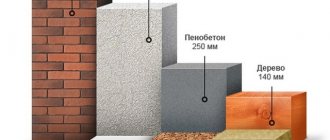
In this case, the walls are strong, but this parameter will directly depend on their size.
Calculation of thickness for external walls of a residential building
Part 1. Heat transfer resistance - the primary criterion for determining wall thickness
To determine the wall thickness that is necessary to comply with energy efficiency standards, calculate the heat transfer resistance of the designed structure, according to section 9 “Methods for designing thermal protection of buildings” SP 23-101-2004.
Heat transfer resistance is a property of a material that shows how capable a given material is of retaining heat. This is a specific value that shows how slowly heat is lost in watts when a heat flow passes through a unit volume with a temperature difference across the walls of 1°C. The higher the value of this coefficient, the “warmer” the material.
All walls (non-transparent enclosing structures) are considered for thermal resistance according to the formula:
R=δ/λ (m 2 °C/W), where:
δ – material thickness, m;
λ—specific thermal conductivity, W/(m °C) (can be taken from the material’s passport data or from tables).
The resulting value of Rtotal is compared with the table value in SP 23-101-2004.
To focus on the regulatory document, it is necessary to calculate the amount of heat required to heat the building. It is carried out according to SP 23-101-2004, the resulting value is “degree day”. The rules recommend the following ratios.
Table 1. Thermal protection levels of recommended enclosing structures of external walls
Heat transfer resistance (m 2 °C/W) / area of application (°C day)
Double-layer with external thermal insulation
Three-layer with insulation in the middle
With a non-ventilated atmospheric layer
With a ventilated atmospheric layer
Expanded clay concrete (flexible connections, dowels)
Cellular concrete blocks with brick cladding
Note. In the numerator (before the line) are the approximate values of the reduced resistance to heat transfer of the outer wall, in the denominator (behind the line) are the limiting degree-day values of the heating period at which this wall design can be used.
The results obtained must be checked with the standards of clause 5. SNiP 23-02-2003 “Thermal protection of buildings”.
You should also take into account the climatic conditions of the area where the building is being erected: different regions have different requirements due to different temperature and humidity conditions. Those. the thickness of the aerated block wall should not be the same for the coastal region, central Russia and the far north. In the first case, it will be necessary to adjust the thermal conductivity taking into account humidity (increased: increased humidity reduces thermal resistance), in the second, you can leave it “as is”, in the third, be sure to take into account that the thermal conductivity of the material will increase due to a greater temperature difference.
Part 2. Thermal conductivity coefficient of wall materials
The thermal conductivity coefficient of wall materials is a value that shows the specific thermal conductivity of the wall material, i.e. how much heat is lost when a heat flow passes through a conventional unit volume with a temperature difference on its opposite surfaces of 1°C. The lower the value of the thermal conductivity coefficient of the walls, the warmer the building will be; the higher the value, the more power will have to be put into the heating system.
In fact, this is the reciprocal of the thermal resistance discussed in Part 1 of this article. But this applies only to specific values for ideal conditions. The actual coefficient of thermal conductivity for a particular material is influenced by a number of conditions: temperature differences on the walls of the material, internal heterogeneous structure, humidity level (which increases the level of density of the material, and, accordingly, increases its thermal conductivity) and many other factors. Typically, the tabulated thermal conductivity must be reduced by a minimum of 24% to obtain optimal design for temperate climates.
Part 3. Minimum permissible value of wall resistance for various climatic zones.
The minimum permissible thermal resistance is calculated to analyze the thermal properties of the designed wall for various climatic zones. This is a standardized (basic) value that shows what the thermal resistance of the wall should be depending on the region. First, you select the material for the structure, calculate the thermal resistance of your wall (part 1), and then compare it with the tabular data contained in SNiP 02/23/2003. If the obtained value is less than that established by the rules, then it is necessary to either increase the wall thickness or insulate the wall with a heat-insulating layer (for example, mineral wool).
According to clause 9.1.2 of SP 23-101-2004, the minimum permissible heat transfer resistance Ro (m 2 °C/W) of the building envelope is calculated as
R1=1/αin, where αin is the heat transfer coefficient of the internal surface of enclosing structures, W/(m 2 × °C), adopted according to Table 7 of SNiP 02/23/2003;
R2 = 1/αexternal, where αexternal is the heat transfer coefficient of the outer surface of the enclosing structure for cold period conditions, W/(m 2 × °C), adopted according to Table 8 SP 23-101-2004;
R3 is the total thermal resistance, the calculation of which is described in Part 1 of this article.
If there is a layer in the enclosing structure that is ventilated by outside air, the layers of the structure located between the air layer and the outer surface are not taken into account in this calculation. And on the surface of the structure facing the layer ventilated by air from the outside, the heat transfer coefficient αext should be taken equal to 10.8 W/(m 2 °C).
Table 2. Standardized values of thermal resistance for walls according to SNiP 02/23/2003.
Residential buildings for various regions of the Russian Federation
Degree-days of the heating period, D, °С day
Standardized values of heat transfer resistance, R, m 2 °C/W, of enclosing structures for walls
Astrakhan region, Stavropol region, Krasnodar region
Belgorod region, Volgograd region.
Altai, Krasnoyarsk region, Moscow, St. Petersburg, Vladimir region.
Areas of use
The different uses of materials in industry are due to the variety of properties. Products obtained by hot and cold methods have different properties. Hot rolled metal plates are most often used:
- in the construction of ships, airliners, cars, the material is used in structures where the joints are connected using hardware and without welding;
- in the construction field, metal is used in the form of load-bearing frame elements and in the manufacture of internal structure elements with subsequent finishing;
- for the manufacture of pipes by soldering;
Cold drawn sheet is used in the following cases:
- in the production of corrugated sheets and for the production of smooth galvanized sheets;
- in automobile production;
- for the production of thin sheet metal with a tin covering layer, used in the production of canning containers;
- in the manufacture of decapir (annealed plates) used in the production of enamelware;
- a high-quality smooth surface requires its painting with powder compositions, nickel plating and chrome plating;
- for cold stamping.
Calculation of the thickness of the external wall according to SNiP
For the conditions of insulating the walls of a residential building in the Perm region (room temperature + 21 o C), the required heat transfer resistance is Rreq = 3.56 m 2 • o C/W.
The heat transfer resistance of the enclosing structure must be no lower than required and is determined by the formula: R = 1/aint + R + 1/aext, where aint is the heat transfer coefficient of the inner surface of the enclosing structure; aext is the heat transfer coefficient (for winter conditions) of the outer surface of the enclosing structure; R is the thermal resistance of the enclosing structure, determined by the formula: R = d1 / l1 + d2 / l2 + d3 / l3 + ⋯, where d is the layer thickness; l is the calculated thermal conductivity coefficient of the layer material.
The thermal conductivity coefficient of the layer material is taken according to the following data.
Insulation - mineral wool
According to the manufacturer of mineral wool thermal insulation Thermal conductivity coefficient:
- Mineral wool - 0.04 W/m/ o C
Insulation - granulated foam glass
According to the thermal conductivity test report, Thermal conductivity coefficient:
- Granulated foam glass - 0.048 W/m/ o C
Aerated concrete walls
According to SP 23-101-2004 “DESIGN OF THERMAL PROTECTION OF BUILDINGS”: Thermal conductivity coefficient:
- Aerated concrete blocks D500 - 0.20 W/m/o C - Appendix E
According to STO 501-52-01-2007 “DESIGN AND CONSTRUCTION OF ENCLOSING STRUCTURES OF RESIDENTIAL AND PUBLIC BUILDINGS USING CELLULAR CONCRETE IN THE RUSSIAN FEDERATION”: Thermal conductivity coefficient:
- Aerated concrete blocks D500 - 0.20 W/m/ o C - table 4.7
- Laying blocks on glue - 0.23 W/m/ o C - table. 7.1
- Laying blocks on mortar - 0.30 W/m/ o C - table 7.1
According to the manufacturer of aerated concrete blocks Thermal conductivity coefficient:
- Aerated concrete blocks D500 - 0.148 W/m/o C
Even if modern manufactured aerated concrete blocks have a lower thermal conductivity coefficient compared to the given regulatory documents, the minimum thermal conductivity coefficient of masonry walls made of aerated concrete blocks, taking into account adhesive masonry, should be taken at least 0.175 W/m/o C.
Foam glass concrete walls
According to the German analogue of foam glass concrete blocks Dennert Calimax 11 Thermal conductivity coefficient:
- Foam glass concrete walls - 0.11 W/m/ o C
With external and internal insulation
The masonry is solid with external slab insulation, the thickness of which is 5 centimeters, and there is also internal plaster:
- for temperatures from -20°С to -30°С – wall thickness 25 cm;
- for temperatures from -30°C to -40°C – wall thickness 38 cm;
- for temperatures from -40°С to -50°С – wall thickness 51 cm.
The thickness of the external wall made of brick with solid masonry with internal insulation using thermal insulation boards having a thickness of about 10 centimeters:
- for temperatures from -20°С to -25°С – wall thickness 25 cm;
- for temperatures from -30°С to -35°С – wall thickness 38 cm;
- for temperatures from -40°C to -50°C – wall thickness 51 cm.
bik ton
The article details where to look for the necessary standards for independent calculations. Examples are given of calculating how thick aerated concrete walls should be for different climatic zones. Information is presented in simple and understandable language.
When constructing private houses, a material such as aerated concrete has become popular. In this regard, the question of how thick aerated concrete walls should be becomes relevant. Many developers claim that a wall made of light blocks with a thickness of 30 to 40 cm is completely self-sufficient, and there is no point in insulating it. To verify such a statement, you need to refer to two documents: SNiP 23-02-2003, which describes thermal protection standards for residential premises; SP 23-101-2004 is a set of rules that must be followed when designing thermal protection.
Wall thickness in a seasonal home (dacha)
In houses where people live only in the warm season, a minimum thickness of aerated concrete walls is allowed (taking into account the density of the selected material). For example, structural and thermal insulation grades with a density of D350-D450 and a strength of more than B2.0 can have a minimum thickness in one-story houses with self-supporting walls of at least 20 cm. If autoclaved aerated concrete is used, then the thickness of load-bearing walls should be from 60 cm, and self-supporting - 30 cm (in accordance with the standards CTO 501-52-01-2007 specified in paragraph 6.2.11).
Types of plastic wall panels
Based on the type of connection between panels, they are divided into three categories:
- seamless slats;
- panel with embossing;
- beveled plastic strips.
Seamless slats
Plug connection allows installation of a continuous cover
The discrete panel joints are equipped with male and female locking locks.
The panel, with its lateral protruding edge, fits into the groove of the next lamella; for this purpose, it is formed almost in the form of a continuous facing plane.
It is not recommended to mount panels directly on walls. There is no need to waste time and materials to get a perfectly smooth fence surface and then cover it with a coating.
Relief panels
The panel has a thin edge on the side that fits completely into the groove of the next strip to a width of 5 mm.
Vertical grooves on the finishing plane visually form the appearance of a fence made of wooden boards (cladding).
Plastic panels with bevel
Panels of this type can be quite wide. The side surface of the lamella ends with a decorative strip (bevel). The connection method is similar to that of embossed panels.
Calculation of insulation thickness for walls
In practice, all these methods are used together, but from an economic point of view, insulating the house, or rather increasing the thickness of the insulation, has a higher priority.
How to calculate the required thickness of walls and insulation so that the house is not only strong, but warm.
Our calculation will consist of two main stages:
- Finding the heat transfer resistance of the walls, which is necessary for further calculations.
- Selection of the required insulation thickness depending on the design and material of the walls.
First, we suggest watching a short video in which an expert explains in detail why you need to install insulation in the outer walls of a brick house and what type of insulation to use.
Heat transfer resistance of walls
To find this parameter we use SP 50.13330.2012 “Thermal protection of buildings”, which can be downloaded on our website (link).
In paragraph 5 “Thermal protection of buildings” several formulas are presented that will help us calculate the thickness of the insulation and walls. In order to do this, there is a parameter called heat transfer resistance and denoted by the letter R. It depends on the required indoor temperature and the climatic conditions of a given city or region.
In the general case, it is calculated by the formula RTR = a x GSOP + b.
According to Table 3, the values of coefficients a and b for the walls of residential buildings are 0.00035 and 1.4, respectively.
All that remains is to find the value of the GSOP. It stands for degree-day of the heating period. You'll have to tinker a little with this value.
The formula for calculating GSOP = ( tB - tOT) x zOT .
In this formula, tB is the temperature that should be inside the room. According to the norms, it is 20-22 0 C.
The values of the parameters tOT and zOT mean the average outside air temperature and the number of days of the heating period in a year. You can find them out in SNiP 23-01-99 “Building climatology” . (link).
If you look at this SNiP, you will see a large table at the very beginning, where climatic parameters are given for each city or region.
We will be interested in the column that says “Duration and average air temperature of the period with an average daily air temperature ≤ 8 0 C.”
Example of calculation of parameter RTR
In order to make everything more clear, let's calculate the heat transfer resistance of the walls (RTR) for a house built in Kazan.
For this we have two formulas:
RTR = a x GSOP + b,
First, let's calculate the GSOP. To do this, we are looking for the city of Kazan in the right column of SNiP 01/23/99.
We find from the table that the average temperature tOT = - 5.2 0 C, and the duration zOT = 215 days/year.
Ventilation gap
The vapor permeability of a wall is a characteristic that shows the presence of natural ventilation. If vapor permeability is low or absent, then there is a need to construct a forced hood. Walls made of natural materials have a natural vapor permeability. They are said to "breathe". Many artificial materials, foam insulation, do not have vapor permeability. Therefore, they block gas exchange through the wall.
Installation of a ventilation gap in a frame house.
A wall made only of mineral wool has a high vapor conductivity. At the same time, condensation accumulates in the insulation, which disrupts the thermal conductivity properties of the insulation. In order for the wall to keep the cold out, it is necessary to properly build the wall pie of the frame house. To protect against vapors from the house, a vapor barrier is made, a membrane film is installed on the outside and a ventilation gap is provided.
A good frame house is insulated with mineral wool with the obligatory installation of a ventilation gap between the insulation and the outer wall cladding. In this case, the outside of the insulation is covered with a vapor barrier membrane, which prevents steam from penetrating into the insulation. But it does not prevent possible steam from escaping from the insulating layer. Thus, the ventilation gap in a frame house is a gap through which wet steam can escape from the wall.
The ventilation gap also prevents condensation on the inside of the cladding.
The need to use a ventilation gap
- If mineral insulation loses its heat-saving properties when wet.
- If the exterior decoration is made of a material that does not allow steam to pass through. In this case, a frame house without a ventilation gap will condense moisture from the inside of the siding.
The thickness of the ventilation space between the insulation and the outer skin is determined by its location and the length of the wall; the longer it is, the wider the ventilation gap should be. The width of the ventilation gap in a frame house from the outside is at least 25 mm. If the wall area is large, it should be at least 50 mm.
Correct device.
Sometimes, in order to reduce the cost of a building, they use penoplex insulation of a frame house. This insulation is airtight and therefore does not require an air ventilation gap. Is a ventilation gap necessary in a frame house?
- The insulation material is vapor-proof.
- External wall finishing allows steam to pass through. Mineral wool can be covered with plaster without a ventilation gap if the plaster mixture has high vapor permeability, higher than that of mineral wool.
In this case, the thickness of the insulation of the walls of the frame house does not require the installation of a ventilation gap inside and outside.
How to calculate wall thickness: calculation example
One of the most important stages in designing a country house, country house or other is calculating the wall thickness. For residential buildings this parameter is very important. After all, incorrect calculations can lead to the house freezing. In addition, you can make a mistake by building too thick walls. In this case, spending on an unnecessary amount of materials will be absolutely in vain. We will talk about what the thickness of the walls should be and how to correctly calculate it in this article.
Why are calculations needed?
Performing accurate calculations will allow you to determine as accurately as possible how thick the walls should be in your home. Nowadays it is very popular to calculate wall thickness online using special automated calculators.
But you need to remember that such a calculation will be approximate. In addition, calculators usually give the total thickness of the wall. While any wall always consists of several layers. And it is very important to understand how the thickness of each layer is calculated separately.
What does the wall thickness depend on?
This indicator is primarily determined by the climate of the region in which the house is being built. The most important indicator in the calculations is the level of resistance to heat transfer. The values of this indicator will vary in different cities. The colder the climate, the higher the required minimum threshold for wall thermal resistance.
Heat transfer resistance is regulated by regulatory documents and has a constant value within each region.
A complete table of the required heat transfer resistance values for cities in the Russian Federation can be downloaded here Thermal resistance table.
Another important factor is the material of the walls. The thermal conductivity of all materials that make up the so-called “pie” is important.
The thermal conductivity values of all possible building materials can be found in the Table of Thermal Conductivity of Materials.
Calculation algorithm
Calculating the thickness of a wall is not as complicated as it might seem at first glance. We will try to avoid complex formulas and explain the basic principles of calculations using a specific example.
Let's say we are building a house in Barnaul. From the table we take the heat transfer resistance indicator for Barnaul. This is 3.54 W/m2 *S.
The house will be built of aerated concrete, the façade will be finished with facing bricks, and the interior will be covered with gypsum plaster.
Here you need to understand that the thickness of the wall is the sum of the thickness of all layers, as is the resistance to heat transfer. The thermal conductivity of all materials is different. And by reducing one of the layers, you will have to increase the other.
So, let's assume that the layer of brick cladding is 12cm thick. Thermal conductivity of facing brick is 0.93 W/m2 *C.
Heat transfer resistance is calculated by dividing the thickness of the material (in meters) by its thermal conductivity value.
So, let's calculate the thermal resistance of the brick layer:
0.12/0.93 = 0.13 W/m2 *S.
The inner layer of gypsum plaster will be 3cm thick. Thermal conductivity – 0.3 W/m2 *C. In a similar way, we calculate the heat transfer resistance for this layer:
0.03/0.3 = 0.1 W/m2 *C.
Now it remains to calculate the thickness of the aerated concrete. It is known that its thermal conductivity is 0.14 W/m2 *C. To understand what thermal resistance aerated concrete masonry should provide, let’s subtract all the calculated values of the thermal resistance of our materials from the minimum threshold resistance to heat transfer in the region:
What to look for when choosing
The moisture content
is taken into account .
If you purchase lumber for a living room, a value of 12% is sufficient. For a wet bath, sauna, take a board with an indicator of 20 - 25%. This is explained by operating conditions - in a damp climate, the material will absorb water and become deformed. Features of choice:
- Pay attention to the thickness of the boards. For housing, a thickness of 20 - 25 mm is sufficient, since there is no heavy load in the rooms. For corridors, verandas, garages, use the parameter 30 – 35 – 40 mm in order to be able to scrape the surface during repairs.
- Check the dimensions are correct . The uniformity of edges and warping of elements are taken into account. The products are inspected for fiber delamination, the presence of mold, and rot at the ends.
Valera
The voice of the construction guru
Ask a Question
It is a mistake to purchase wet lumber in the hope that it will dry by the time of installation. Self-drying will lead to deformation, since there are no chambers where gradual and uniform release of moisture occurs.
Calculation of wall thickness
The walls must be warm! What are warm? These are superior to SNiP in terms of thermal conductivity! First you need to figure out what they should be in accordance with SNiP. It's not as difficult as it seems at first glance.
The first question that arises is: “how many days a year does the heating season last?” Maybe we don’t need to heat anything at all and we live in India. However, harsh realities suggest that out of 365 days, 202 air temperatures were ≤ 8 °C. But this is in my Lipetsk region, and in yours the numbers are probably different. Which? SNiP 01/23/99 will answer this question. In it we look for table No. 1, in it we look for column 11 and our locality. The number at the intersection is the number of days where the temperature is below 8 degrees.
Why was all this necessary? In order to open SNiP 02/23/2003, find the formula in it and determine the degree-day of the heating period. The value shows the temperature difference between the external and internal air, that is, “how much to heat.” Multiplied by the number of these days, that is, “how many days to heat”
Well, we found out. What's the point of this? And this one! At this stage, we get some figure, in my case it turned out to be 5050. Using this figure, from the same SNiP in Table 4, we look for what the normalized value of the heat transfer resistance of the walls is (3rd column). It turns out something between 2.8-3.5, by interpolation we find the exact value (if necessary and interesting) or take the maximum. I got 3.2°C/W.
Now, to calculate the thickness of the wall, we need to use the formula R = s / λ (m2•°C/W). Where R is the heat transfer resistance, s is the wall thickness (m), and λ is the thermal conductivity. Now imagine that we decided to build our entire wall from gas silicate blocks. In my case, these are blocks of the Lipetsk silicate plant. You need to find out the thermal conductivity coefficient. To do this, go to the website of the manufacturer of your material, find your material and look at the descriptions of the characteristics. In my case, these are blocks made of cellular concrete and the thermal conductivity coefficient is 0.10-0.14. Let's take 0.14 (humidity and all that). Using the above formula, we need to find S. S = R * λ, that is, S = 3.2 * 0.14 = 0.45 m.
The wall turned out good. And darling. There is probably a way to save money. What if we take a block 20 cm thick and make a wall out of it. We obtain a heat transfer resistance of such a wall equal to 1.43 (m2•°C/W), and in our region it is 3.2 (m2•°C/W). It won't be enough! What if we make a multilayer wall and use foam plastic on the outside of the wall, or better yet, mineral wool, because they have approximately the same thermal conductivity coefficients, but mineral wool is environmentally cleaner and also does not burn. And the mice somehow don’t like her. We just have to figure out the heat transfers. 3.2 - 1.43 = 1.77 (m2•°C/W). Now everything is simple again. Since my wall is three-layer and the outside is lined with brick, I need to choose the insulation that is best suited for this purpose. I chose ROCKWOOL KAVITI BUTTS, its maximum indicated thermal conductivity is λ = 0.041 W/(m K) and I calculated S = 1.77 * 0.041 = 0.072. I made a wall from a 20 cm gas silicate block and 7 cm of stone wool. Do you agree that it is better than 45 cm of gas silicate? Or maybe just give up on everything and make a frame with insulation? It’s possible))) in Canada and many European countries everyone does this. But we are Russians! Therefore, we will cover this entire facility with facing bricks, and it will be beautiful and practical for us! Why didn't we take facing bricks into account? It just doesn’t have any energy-saving functions. Moreover, it is necessary to make ventilation gaps in it. But that is another story.
Ultimately, having decided that the requirements of SNiPs were constantly increasing, I made insulation 10 cm thick. Moreover, it did not cost much more.
Floorboard dimensions
Solid boards are packed according to the single-length and multi-length principle. In the first version, the pack contains identical elements, in the second - one piece along the length of the floorboard, several short ones. This saves material and creates a beautiful combination when laying. The solid board has dimensions: width 90 – 150 mm, length 300 – 900 mm, thickness 16 – 40 mm.
Terrace boards are produced up to 6 m long, 90 – 250 mm wide, and up to 48 mm thick. For rectangular areas, identical parts are installed; corner rooms and rooms in the shape of the letter L are assembled with elements of different lengths.
Glued boards are available in dimensions: width 120 - 150 mm, thickness ranges from 18 - 50 mm, board lengths range from 1.5 to 6.0 meters. The elements are installed parallel to the sides of the site, sometimes placed diagonally. The latest floor model is produced with excessive material consumption for cutting corners.
Calculation of insulation thickness for walls, floors, roofs
After the completion of the construction of a residential or commercial premises, there comes a time when the issue of wall insulation becomes relevant. Thanks to the development of the construction industry, there is now a huge selection of thermal insulation. And each type of building material should be approached with precision and at a professional level, and a correct calculation of the thickness of the insulation should be made.
Main indicators for choosing building materials:
- insulation thickness;
- type of insulation;
- wall thickness;
- the material from which the walls are built.
Accuracy of calculation of insulation thickness
Using these indicators, it is very important to correctly calculate the thickness of insulation for walls, roofs and floors. This process must have a correct calculation of the dew point in the thickness of the walls and insulation.
This parameter affects the freezing of walls and the thermal insulation of the house, therefore, in no case should you save on the purchase of insulation products.
When choosing, you need to take into account: thermal conductivity indicators, layer thickness. Thanks to these data, it is necessary to accurately calculate the temperature resistance of the material using the formula R=d/k.
Note: d is layer thickness, k is thermal conductivity.
It should be noted that this formula is used exclusively to calculate the thickness of insulation in a single-layer structure.
The thermal conductivity parameter of the building material can be found in the attached documentation or on the Internet.
The second and most important indicator for the correct calculation of insulation thickness is the external temperature indicator.
Calculation of insulation for walls
When calculating, you should use the following indicators:
- wall thickness;
- material used to build walls;
- temperature difference between outside and inside.
Using the technical data of all layers and average calculations, the heat transfer coefficient of the walls is 3.5. As practice shows, the thickness of the insulation depends on the thickness of the walls in the room. As a rule, the calculation of the thickness of insulation for walls is calculated in inversely proportional order. Therefore, with a lower thermal resistance coefficient of the walls, the thermal insulation layer must be larger.
Calculation of insulation material for floors and roofs
As practice shows, special insulation should be used for these surfaces. The load that will be placed on the roof depends on the calculation of the thickness of the roof insulation. If the calculation is incorrect, it is very easy to make the structure heavier.
- The thermal insulation value for the roof and attic floors is 10-30 cm.
- Basements use an indicator of 6-15 cm.
Before installing insulation for the roof, it is mandatory to use waterproofing after the construction of the attic space.
Thanks to it, all load-bearing walls and ceilings will be protected from the penetration of fungus and mold.
Quality classes
Enterprises develop technical specifications (TS) based on GOSTs and regulatory requirements.
They provide quality regulations. There are generally recognized classes of boards:
- Extra. The products do not have a single flaw on the surface. The boards are smooth, with clearly defined dimensions. The cost of such a board is high, because it is difficult to find areas without knots in a fallen trunk in order to get closer to the standard.
- Class A. Allowed per linear meter of lumber is 1 live knot (without falling out) and a minimum number of cracks not to the full depth. The middle part of thick logs is often used for production.
- Class B. Allowed for 2 knots or resin pockets per linear meter, one crack (up to 3 cm) or chip, as well as vague darkening in the form of individual spots.
Class C is considered the lowest quality . Up to 4 knots or resin pockets, chips, unevenness, and cracks are allowed per linear meter. They allow violation of the geometry of the groove or protrusion, and the curvature of the boards.
Visible sheet defects
During the manufacturing process, surface defects or dimensional deviations occur. They are classified into certain categories. The appearance of deviations and defects of a certain type is characterized by improper organization and equipment of the production process.
Scratches, irregularities, oblique cuts
Such violations are characterized by the appearance of mechanical damage to the strip in the form of depressions across and along the rolling direction. Deviations in dimensions in length and width from the standard specified parameters are diagnosed by an amount exceeding the permissible values. On the surface, protrusions of material are formed along the width and length at the edges of strips or sheets, having a right angle with the surface.
The reasons causing such deviations from the norm may be:
- metal elements of equipment protruding beyond normal limits, sometimes defects are caused by stuck pieces of metal;
- poor adjustment of flying or disc shears, or their weak fastening during installation;
- untimely sharpening of knives;
- crescent shape of the strip itself;
- improper organization of feeding of rolled strip into the cross-cutting machine;
- unprofessional setting of pulling and feeding rollers.
Fat, wave, scatter and crescent
A slight waviness of the rolling strip appears along both edges or only on one side. On the surface of the plate, prints of various sizes and shapes are visible in the form of elongated spots or stripes. Smoothness is disrupted by the appearance of sharp holes, grooves and imprints of mechanical origin.
There are kinks and bends on the plate in different directions, corners and edges are often bent. When packing sheets into bundles, a shift in the size of the sheets along the width or length of the package relative to each other appears greater than the permissible norm. Damage of one kind or another is noted on the side edges, the corners may be curled, and the strip itself has a crescent shape.
Defects are caused by the following reasons:
- misalignment of feed and receiving rollers or rollers;
- poor adjustment of the correct rollers and disc knives;
- waste and other metal parts stick to the rollers and straightening rollers;
- the strip is not protected when cutting from small metal shavings and parts;
- jamming of rolled material in packaging devices;
- improper threading of the strip for advancement with pulling and straightening rollers, sagging and pressure on the roll screws from the outside;
- careless adjustment of wiring fittings, malfunction of the conveyor belt, incorrect height adjustment of the pocket and lifting table;
- installation of stops in baling units (in their pockets) in violation of standards;
- Incorrect adjustment of scissors and loosening of vertical rollers and wires.

