Decorative lighting using LED strips has come into fashion relatively recently. Many users have not yet had time to understand the specifics of operation and the features of connecting lamps. In particular, not everyone can choose the right cable for an LED strip. This is an important issue, since an incorrect connection can cause the backlight to fail.
Calculator
Calculation of cable cross-section can be done using a calculator.
According to the current regulatory and technical documents and the conditions of normal trouble-free operation, during operation, long-term current loads on cables are determined, first of all, by their diameter and the material from which they are made. Reducing the standard cross-sectional area of current-carrying busbars is, of course, economical. This step significantly reduces the cost of the required materials and work, but critically increases the risk of overheating of the wiring, destruction of insulating coatings and the occurrence of short circuits with further, much worse, consequences. This may cause fire or electric shock to people.
On the other hand, excessively exceeding the cross-section of conductors leads to a significant increase in costs for materials and installation work, which is also undesirable. A calculator for calculating wire cross-section based on power consumption can be easily found online, but, as a rule, this kind of program is very demanding in terms of accuracy and the number of initial parameters. There are times when a calculator for calculating cable load is not available, or information on parameters is incomplete and speculative.
So how to calculate the cross-section and length of the cable so as not to lose money and comply with safety standards? There are such ways. To begin calculating the cross-section of the wire based on power consumption, it is necessary to calculate this estimated power consumption. This is done according to the formula:
P = (P1+P2+..P n )*K*J
Where:
- P—total power consumption;
- ( P 1… Pn ) - power of consumers from 1 to n;
- K - simultaneity coefficient, shows the number of consumers simultaneously using the network (conventionally accepted as 0.8);
- J is the safety factor, shows the estimated value of the power reserve for possible future consumers (usually taken equal to 1.5-2).
In addition to power, an important factor when choosing a cable is the material of manufacture. Different materials have different resistivities and, accordingly, produce different voltage drops over a constant length. Copper and aluminum are predominantly used. The choice is ultimately up to the consumer. Data for the most common voltages in everyday life and industry are given in the tables below.
Cable cross-section by length and load
In everyday conditions, in the process of manufacturing cables, wires and extension cords, the following formula is used:
I = P / U * cos φ, in which:
- I - current strength, (Amps);
- P - power, (Watts);
- U—mains voltage, (Volts);
- cos φ is a dimensionless coefficient, usually taken equal to 0.95–1.
Using this formula and the table below, you can quickly select the optimal transverse diameter for a specific length of the busbar.
Dependence of power, current and wire length on cross-section
An example calculation is as follows: for a cable 75 meters long with a current of 20 amperes with an estimated power consumption of 4.5 kilowatts, you should choose a wire with a total cross-section of 10 square millimeters. You can use a single-core cable with the same cross-sectional area, or a multi-core cable with the same total area. It should be mentioned that when determining the length of the proposed wiring, it is necessary to provide some margin - about fifteen to twenty centimeters - for the proposed switching (terminals, welding, soldering, etc.).
Which to choose
A large selection of touch switches causes certain difficulties in selecting the optimal option. Such products are boards with average dimensions of 40 × 10 × 2 mm, allowing them to fit into an LED profile, external modules placed in a plastic case, or a controller equipped with a remote control.
We advise you to pay attention to the wireless pass-through switch, which is also convenient to use, especially when lighting long corridors. By turning the light on at the beginning, you can turn it off at the end.
To choose the appropriate option, you must first decide on the type of LED switch. After this, it is worth considering the technical specifications. Noteworthy meaning:
- The voltage that is supplied to the input of the device and created at its output;
- The strength of the current flowing through the device in standby mode and generated when the load is connected;
- Power.
If you decide to install a monochrome LED strip, you should decide on the operating principle of the circuit breaker. Manufacturers offer devices:
- Capacitive, inside of which there is a spring that fits tightly to the plate. When your hand touches the switch, it creates a vibration. As a result, the contact closes and the lighting turns on. However, having decided to opt for such a device, it is worth considering that if the thickness of the plexiglass diffuser is more than 1 mm, you may encounter a lack of operation. This will cause serious inconvenience during operation;
- Infrared, triggered every time there is an object at a distance of 10 cm from the surface, from which the signal is reflected and returns to the receiving element. If the gap between the protective screen and the sensitive element exceeds 5 mm, you will have to use a profile with a shallower depth or take care of the presence of a hole in the light-scattering lens.
If the choice is made in favor of a model with a dimmer, you should also decide on the principle of operation. Such touch switches are most often turned on/off by a short touch. To change the brightness, you need to hold your hand longer on the control panel.
Some models have a slightly different operating principle. They can have several pre-programmed operating modes. Similar devices are suitable for RBG tapes. They are equipped with a control panel equipped with a touch ring. To change the shade of the glow, you need to smoothly move your finger along the spectral circle. As a result, diodes of the selected color or a combination of them will be switched on.
Attention! When choosing a switch, pay attention to the frequency of the PWM pulses. It should be more than 300 Hz so as not to have a negative effect on vision and the nervous system.
Selecting wire cross-section by length
You should be aware that the length of the wire (cable) affects the voltage. The longer the line, the greater the voltage loss. To avoid this, you need to increase the cross-section of the conductor. How to calculate all this?
You have certain consumers of electricity in your home; in total they amount to 5000 W or 5 kW. The length to these consumers from the circuit breaker is 25 m. Since electricity is supplied through one wire and returned through another wire, the length doubles and is equal to 50 m.
Next we need to find the current strength (I). You already know how to find it. You need to divide the power by the voltage:
I = 5000/220 = 22.72 A
Using current (A) or power (P) in Table 2, we determine the cross-section of the wire. According to the table, this is 1.5 mm² of copper wire.
Since the wire has its own resistance (R), we make the calculation taking into account the following data using the formula:
R – conductor resistance, Ohm;
p – resistivity, Ohm mm²/m;
L – wire length, m;
S – cross-sectional area, mm².
From the formula: value (p) is always a constant value. For copper it is 0.0175, and for aluminum it is 0.0281.
R = 0.0175 × 50/1.5 = 0.583 Ohm
Now you need to calculate the voltage loss using the formula:
dU – voltage loss, V;
R – conductor resistance, OM.
dU = 22.72 × 0.583 = 13.24 V
13.24 V / 220 V × 100% = 6.01%
Since the percentage of voltage losses is higher than 5%, the cross-section of the wire (cable) instead of 1.5 mm² we choose 2.5 mm².
That's the whole calculation. Difficult? No.
Conclusion
You learned how to choose the right wire (cable) cross-section for household (and not only) use. As you can see, it is not so difficult to do all this. You just have to count it once and that’s it. After such a calculation, you will be completely confident that the wires or cables you have selected will not let you down and will last for many years.
Multicolor
If you want to connect an RGB color strip at home, the connection technology will not change much. A controller will be added to the circuit with a multicolor device, without which the circuit will not be able to work, and the output will also have 4 contacts instead of two. We also looked at connection diagrams for RGB strips, and we present them once again to your attention.
Two power supplies:
Otherwise, the connection instructions are similar to the previous one - the wires are soldered, the exposed contacts are insulated, after which the correct connection of all circuit elements is checked! You can clearly see how to connect a multi-colored RGB strip to the network with your own hands in the video below:
That's all we wanted to tell you about how to connect an LED strip to 220 volts with your own hands. As you can see, the instructions for connecting a multi-color and a single-color model are not very different, the main thing is to correctly connect the wires by color. If you suddenly have any questions, you can ask them using the Question an Electrician form!
To power the LED strip from a regular household AC network 220V 50Hz, three conditions must be met:
- convert AC network voltage to DC;
- equalize voltage levels: reduce the mains voltage to 12V or change the LED connection circuit so that high voltage can be supplied to them;
- stabilize electrical power parameters.
Read also: VGA hdmi cable diagram
The easiest way is to use a ready-made power supply for a 12V LED strip; it is designed for a safe voltage. But there are also disadvantages to using this power supply: it costs money and is not so easy to assemble; in addition, due to the low voltage, LED strips should not be placed far from the power supply; thick wires will have to be used to compensate for voltage losses.
The second option: remake the LED strip and instead of switching LEDs in series-parallel, use serial LEDs. With this connection scheme, the LED assembly is powered by a low current, but at a high voltage. In addition, if you sacrifice galvanic isolation, the power driver circuit is greatly simplified. Attention. Circuits without galvanic isolation from the network can be used where there is no danger of electric shock, for example in a dry room on the ceiling.
The most interesting thing is that a circuit for such a driver can be made from parts of a used energy-saving light bulb!
Let's consider connecting an LED strip to a 220V network; the diagram is shown in the figure.
Table of nominal values of circuit elements:
- C1 – 2.2 µF 400 V
- R1 – 1.3 kOhm
- R2 – 4.3 kOhm
- R3 – 47 Ohm
- VD1 .. VD4 – 1N4007
- VT1, VT2 - 13002
Three nodes can be distinguished in the diagram:
- AC voltage rectifier and filter on elements C1, R1, VD1 – VD4;
- current stabilizer on R2, R3, VT1, VT2;
- assembly of LEDs HL1 – HLN.
You can read about the operation of the rectifier here. In this circuit, in addition to the diode bridge of 4 diodes, a current-limiting resistor R1, which protects against current surges, and a filter capacitor C1 are added. When a mains voltage of 220V/50Hz is applied to the input of this rectifier, a constant voltage of approximately 300V with a ripple frequency of 100Hz will appear at the output of the rectifier (on capacitor C1). The greater the capacitance of the capacitor, the less ripple will be.
LEDs require power supply with a stabilized current; they are often supplied with a stabilized voltage through a current-limiting resistor, for example, as in LED strips. But why should we make compromises if it is easier to make a current stabilizer that operates at high voltages than a voltage stabilizer? The operation of the current stabilizer circuit was discussed here.
And the last element is a sequential assembly of LEDs from a strip. A standard LED strip is assembled according to a circuit of three serial LEDs and one current-limiting resistor. Such a section is connected in parallel to a bunch of other similar sections and all this is connected to 12 V. The voltage drops from 3.3 V to 3.6 V on each diode, thus leaving about one and a half volts for the current-limiting resistor.
To increase the voltage, sections of three diodes are connected in series with each other, and the resistor can be removed, short-circuited, or replaced with jumpers, i.e. whichever is more convenient from a topological point of view. Attention. Observe the polarity; if an error in the polarity of connecting the LED at such a voltage will be fatal for the LED.
The current that flows through the three LEDs can be approximately calculated by dividing one and a half volts by the resistance of the current-limiting resistor. That is, with a resistance of 150 Ohms, the current through the LEDs will be 10 mA.
I came across just such a strip with 10 mA LEDs, and the driver parameters were calculated for it. If you need to reduce the current, you will have to proportionally increase the resistance value of resistor R3.
With a mains voltage of 220 V, the described circuit is capable of providing a serial connection of up to 25 groups of three diodes or 75 individual ones. If the network voltage is often low, then it is better to reduce the number of LED groups to 20 or even 15.
And here is the board from the energy-saving paw, from where you can get the necessary radio elements.
The light bulb broke, but the board remained in working order.
By the way, the polarity of diode connections and transistor terminals can be copied directly from this board, everything you need is marked there. We extract elements from this board and assemble a new circuit. The photo shows that transistors in a low-power TO-92 package such a package will not dissipate power more than 600 mW. And the total power of a circuit with such a transistor will not allow it to supply more than a couple of watts to the load. If you need to assemble a circuit for a more powerful load, then transistor VT2 should be in a more powerful package and preferably with a radiator.
2 thoughts on “Connecting an LED strip to a 220V network diagram”
Using a CFL board, you can do without the hassle of cutting the tape into small pieces and soldering them, rectifying the voltage, etc., and without hemorrhoids with continuity if one piece fails. Not to mention the lack of galvanic isolation from the network, which is generally unacceptable for use by untrained people. We simply use the ballast as a switching power supply.
1. Remove the capacitor connected only to the 2 terminals of the lamp, as well as the (burnt out) lamp itself. We close the connection points of its 2 other terminals with a jumper.
Read also: Equipment for turning shop
2. We turn the choke into a transformer. Why do we solder it, throw it into a container of water, bring it to a boil, take it out, and disassemble it. We insulate the existing winding, wind a second one on top (10..20 volts, d 0.3..0.5, it is better to wind it from several thinner ones).
3. We assemble the trans, solder the primary to the board with short wires. To the secondary there is a rectifier - a bridge of RF diodes and 470..1000 µF x 25..35V, with a load of the required power (for example, a 12V auto lamp). We connect a 220V 40..60W (incandescent) lamp in series with the ballast in case of installation errors. Turn it on briefly. If the small lamp is on and the big one is not, we continue. Otherwise, we are looking for an installation error, or a malfunction on the ballast board.
4. Remove the large lamp and connect a voltmeter to the small one. Turn it on briefly and measure the voltage. We adjust the number of turns of the secondary and measure again. If we achieve 11..13.5V, we connect as a load the piece of tape that we will power from our device. We measure the voltage and adjust the turns if necessary.
5. We isolate the secondary, assemble the trans with glue, and solder it in place. We also remove the rectifier.
6. Cut the tape into an EVEN number of pieces, connect them into TWO parallel groups - in each of them “+” to “+”, “-” to “-“. And we parallel the groups with each other in reverse - “+” 1st to “-” second. We connect the resulting “sandwich” to the secondary. We check and finally assemble the structure.
LEDs work great during breaks due to back-to-back connection, each group at its own half-wave, and protecting each other from reverse voltage. To eliminate flicker at 50Hz, we change the filter capacitor (usually 1 µF x 450V) to 5..20 µF (1..2 µF per 1 W of load power). It is also advisable to replace the transistors on the ballast board (usually MJE13001) with more powerful ones (MJE13005, MJE13007, or lastly MJE13003), at least during setup. If the power consumed by the tape exceeds 70% of the declared lamp power, it is mandatory.
Naturally, when repeating the design with the same ballast and a slightly different load, there is no need to select the turns again. If you have an RF voltmeter, you don't need a rectifier.
Thus, I converted more than a dozen table lamps with burnt U-shaped 6/9W LLs to LEDs, simply by gluing pieces of tape accordingly. length to the standard reflector over its entire width. For those wishing to repeat: do not use hot melt glue, they get quite hot during prolonged use!
Shouldn't the other end of R2 be connected to “+” in the diagram? Otherwise, the resistor in your circuit will burn out.
Reading time: 5 minutes No time?
We will send the material to you by e-mail
Not so long ago, the only way to illuminate private houses and apartments were all kinds of chandeliers. At that time, spotlights and decorative lighting were not yet used. Modern interior designs are complemented by various light sources. In this case, various methods are used. Decorative design techniques are especially popular. In this article we will talk about how to implement a circuit for connecting a 220V LED strip to a network. You can install this design yourself. Similar LED technologies are used in every interior. This is an excellent opportunity to illuminate individual decorative elements, highlight the edging of furniture and emphasize the desired geometry of the room.
A simple LED product circuit contains a power supply and a controller mechanism
FAQ
How to calculate the length of the tape
The calculation is made taking into account the power of one meter and the length of the circuit. The required length of the LED strip will also depend on the required brightness of the light flux.
What does it take to make an LED strip work for a long time?
In order for the purchased LED strip to serve the number of hours allotted by the manufacturer, you must follow some rules during operation:
- power must be supplied from a source with a constant voltage not exceeding the specified permissible value;
- the protection class must strictly correspond to the operating conditions;
- the tape should not be exposed to chemically aggressive vapors;
- the temperature during operation of the belt should not go beyond the permissible range (from -25 to +45 degrees);
- the tapes are not mounted on heated surfaces, do not wipe and eliminate mechanical impact.
Knowledge of installation and operation features allows you to use even inexpensive tapes for a long time.
Why can the tape only be cut in certain places?
On the conductive strips there are marks for a possible cut at the contact pads for connecting wires. Only there can the tape be divided into parts along the dotted line with the image of scissors.
Do RGB strips have multi-color LEDs or just three-color LEDs?
Shades of color are created by the glow of three different crystals. Their radiation is mixed, and as a result, a standard three-color tape can be mistaken for a product with diodes of different shades.
Can LED strip be used underwater?
Tapes with a degree of protection IP65 and higher are not afraid of moisture. IP68 can work under water for a long time thanks to the waterproof silicone shell.
Why are the remote LEDs of a long strip dim?
When installing a tape of too long a length, as it moves away from the batteries, a loss of voltage occurs, which causes a decrease in the glow power.
For what kind of lighting can LED strip be used?
LED strips of sufficient power are successfully used for basic lighting. This is cost-effective due to low energy consumption, long service life and ease of maintenance.
What is the operating voltage for LED strip?
Lamps powered by mains voltage 220V are used, as well as varieties with operating voltages of 12, 24 and 36 V.
Sealing tape
According to the degree of moisture protection, tapes are divided into 4 types:
- IP-20
They do not have a protective coating and can only be used indoors in dry rooms.
- IP-33
It has a double layer of varnish that protects from dust, but not from water. Can be distinguished by its characteristic shine.
- IP-65
With protection against dust and jets of water.
- IP-68
Completely immersed in a silicone shell and have double insulation of wires.
They can be used in water to illuminate pools and aquariums.
For indoor installation (furniture lighting, ceiling lighting in a bedroom, living room), some choose a sealed LED strip with IP65 protection. It is not completely in the silicone hose, but is simply spilled with sealant on top.
This gives it protection from splashing water. People think it will be cool and convenient to dust it.
However, using such a model in a dry room will never justify itself. You will get more cons than pros.
In such rooms, especially during the winter heating period, low humidity is observed. And the sealant applied over the tape under such conditions tends to dry out quickly.
In some cases, silicone will simply crumble like glass and crumble. And this silicone begins to “lead” when it dries.
It pulls the substrate along with it and the connections to the board break. The contact begins to disappear and the backlight goes out in places and does not burn evenly.
No amount of repairs will help here. The whole thing will have to be changed.
And many people are unable to properly seal the sealing tape. It has its own nuances and features.
The same silicone begins to turn yellow over time, which ultimately changes (contaminates) the color of the backlight. Checking the quality of silicone in a store is problematic.
This effect (yellowing) will only appear after a few months. Don't forget about the smell that will invariably emanate from the sealant when the tape heats up.
Therefore, use sealing tape where it belongs - in wet areas of bathrooms, in the kitchen under the apron, near the sink.
Selection of cable cross-section for 12 volt current
Selecting wire cross-section and fuse
Wire selection table depending on load current and ambient temperature.
Wire cross-section, mm 2
Permissible current (A) depending on the ambient temperature, C
When choosing a wire, you need to take into account its length and the method of laying it (in a bundle, corrugated or separately). Below is a more detailed table taking into account the length of the wire.
The maximum cable length (in meters) from the energy source to the consumer with a voltage drop of less than 2% for 12V systems. That is, the values inside the table are the length of a wire of a certain cross-section and the current passing through it, at which there will be a voltage drop of 2%.
Cable cross-section, mm 2
For example, when connecting a car radio, we need 1 meter of wire, the current consumption is approximately 10 amperes. Looking at the table, we see (highlighted in green) that we need a wire with a cross section of 1.5 mm 2. (10 - Current, 1 - length, 1.5 - wire cross-section).
When choosing a wire, you must not forget about the fuses; in the event of a short circuit, the fuse should blow, not the wire. The fuse should be located as close as possible to the power source or to a larger rated distribution fuse. Using the following table, you can roughly select a fuse only to protect the wire where the load will be constant. For loads with large starting currents, for example a starter, a winch, the fuse rating must be calculated taking into account the starting current of the consumer. The fuse can withstand short-term overloads; if 35% of the rated current is exceeded, the fuse will blow in a matter of seconds or instantly (depending on the manufacturer).
Source
Recommendations for placement of equipment and installation of LED strip
- Determine for yourself the method of installing the SDL. This is important when choosing it, because Not all SDLs are equipped with self-adhesive tape. In this case, they are attached to brackets and clamps.
- Carefully prepare the surface on which the tape will be applied. For more reliable fixation, additionally cover the entire path with double-sided or aluminum tape and apply instant glue.
- During the gluing process, the protective coating of the self-adhesive layer is removed gradually as it progresses.
- In order to save money, the plastic profile of aluminum channels can be replaced with a plastic corner. It is attached with glue/liquid nails.
- When designing ceiling lighting, remember the degree of light dispersion. For the most effective lighting, the distance from the ceiling to the mounting location of the board should be at least 80 mm.
- To illuminate signs, display cases, and cabinet shelves, choose side-illuminated SDLs. This will help avoid being blinded by crystals and highlight the required interior details.
- Boards longer than 5 meters are connected to the power source in parallel. Otherwise, it will lead to damage to the diodes.
- PSUs equipped with a fan have a specific sound. Therefore, it is worth considering the location of its installation outside recreation areas. The controller, on the contrary, should be located nearby for ease of control from the remote control or manually.
- Choose trusted manufacturing plants. This will help you avoid unnecessary expenses.
How to use the section selection table?
Table 2 is very easy to use. For example, you need to power a certain device with a current of 10A and a constant voltage of 12V. The line length is 5 m. At the output of the power supply we can set the voltage to 12.5 V, therefore, the maximum drop is 0.5 V.
Available - wire with a cross-section of 1.5 square. What do we see from the table? At 5 meters with a current of 10 A we will lose 0.1167 V x 5m = 0.58 V. It seems to be suitable, considering that most consumers tolerate a deviation of +-10%.
But. After all, we actually have two wires, plus and minus, these two wires form a cable on which the load supply voltage drops. And since the total length is 10 meters, the drop will actually be 0.58 + 0.58 = 1.16 V.
And this is without taking into account the contact resistance of the contacts and the imperfection of the wire (“sample” of copper is not the same, impurities, etc.)
Therefore, such a piece of cable most likely will not work; you need a wire with a cross-section of 2.5 square. It will give a drop of 0.7V on a 10m line, which is acceptable.
What if there is no other wire? There are two ways to reduce voltage loss in wires.
1. The 12.5 V power supply should be placed as close to the load as possible. If we take the example above, 5 meters will suit us. This is what they always do to save on wires.
2. Increase the output voltage of the power supply. The risk is that as the load current decreases, the voltage across the load may rise to unacceptable limits.
Battery powered
This connection option allows you not to use electricity, which is convenient in some circumstances. Powering the LED device from batteries is possible if you plan to connect a short section with low power for short-term use. In this way, you can connect duralight, for example, to illuminate shelves, pictures or a work surface in the kitchen.
Any batteries will do; their total voltage should be from 8 to 12 V.
The work order is as follows.
- Strip the contacts on the batteries, tin the ends of the wires and solder them to the plus and minus of the battery, respectively.
- When connecting the toggle switch, the plus from the battery is connected to its input, and the output is connected to the minus of the duralight.
- Solder the free ends of the contacts to the tape, remembering the polarity.
LED strip connected to a battery.
Features of installing the power supply
Power supplies for LED strips are usually installed in accordance with the block diagram that comes with them. Basically, before installing the transformer, the LED strip is cut into sections consisting of the required number of diodes.
The cutting places are indicated by two pairs of contact groups (at each end of the section) and a marker in the form of scissors. The power supply is connected parallel to the sections. During the connection process, it is necessary to observe polarity (connect the power supply terminals marked “+” and “-” to the corresponding contacts of the tape), and it should be taken into account that the output voltage of the source should not exceed 12 or 24 V (the rated voltage of the tape). The location of the power supply does not affect the functionality of the device, but it must be selected for aesthetic reasons.
In practice, two schemes are used for connecting the LED strip to the power supply.
Connecting an LED strip to one power supply
Most often, an LED strip is a solid five-meter piece that is wound on a plastic reel. As a rule, from the outside - on the end that is not wound on the reel - the wires necessary for connecting to the power supply are connected to the tape. If after purchase you find that there are no connecting wires, then you should take any stranded wires of red (“+”) and black (“-”) colors, measure the required length, which should be enough to reach the terminals of the power supply, and solder them, having previously cleaned and tinned both ends.
- We tin the wires using rosin and tin, and connect them to the tape tracks using soldering.
During the soldering process, you should use a low-power soldering iron and make the connection quickly enough, since there is a possibility that the LEDs may be damaged due to exposure to elevated temperatures. Wires need to be serviced quickly to avoid overheating them and damaging the LEDs. - After this, we connect the free ends of the wires (not soldered to the tape) to the power supply, observing the polarity.
The red wire from the LED strip (“+”) must be connected to the “+V” terminal, and the black (“-”) to the “-V” terminal; The mains voltage is connected to the “L” and “N” terminals (“L” is phase, “N” is zero)
Video: connecting a sealed power supply
Connecting two LED strips to one power supply
As an example, consider the following option: the installation and connection of an LED strip, the length of which is 8 meters, is planned. The problem is that it is quite difficult to find a piece of tape of this length, since LED strips are mainly sold in 5-meter reels. However, 8 meters are still required, so what to do?
If you need to connect several pieces of LED strip with a total length of more than 5 meters, this can only be done using a parallel circuit
Everything is quite simple. We perform the following actions:
- We purchase two reels of LED strip, leaving one piece whole (5 meters), and cutting 3 meters from the second and connecting them. In order to cut the tape, take ordinary scissors and look for a line along which we will cut a piece of the required length.
- Next, we clean and service the contact pads of both pieces of tape (on the same side).
- We take four two-wire wires (two red “+” and two black “-”) and also prepare them (we strip and tin).
- Solder to two pieces of tape. We solder (screw) the free ends of the wires coming from a five-meter piece to the power supply terminals (“+V” and “-V”), and connect the wires of the network cable to the “L” and “N” terminals.
- Next, on the wires that are connected to a five-meter piece of tape, we remove small pieces of insulation.
Then we tin them and solder wires from a three-meter piece to them, thereby connecting both pieces of tape in parallel. If the corresponding wires from each tape are brought to one point, you get a parallel connection
Where are they in demand?
The need to connect an LED lamp or strip may arise in various situations. Most often, these lighting devices are used if necessary:
- Ensure sufficient lighting of the work area in the kitchen;
- Connect several lighting fixtures at once;
- Organize lighting of staircases and landings;
- Connect the smart home system.
The location of the LED strip in the kitchen is chosen taking into account the goals being pursued. If you need to organize LED lighting for the work area, choose a powerful light source, which is located directly under the cabinets. This option is the most popular, as it helps prevent negative effects on the eyes due to insufficient light levels and makes it easier to care for the countertop.
Integrated lighting is selected for the space around the hood or for furniture. The LED strip is mounted above the upper cabinets or placed under the lower ones. Sometimes they are fixed under the tabletop.
Cable resistivity table
Home > Theory > Copper resistivity
Formula for calculating conductor resistance
What is electric current
At different poles of a battery or other current source there are opposite electric charge carriers. If they are connected to a conductor, charge carriers begin to move from one pole of the voltage source to the other. These carriers in liquids are ions, and in metals they are free electrons.
Definition. Electric current is the directed movement of charged particles.
Resistivity
Electrical resistivity is a value that determines the electrical resistance of a reference sample of a material. The Greek letter “p” is used to denote this quantity. Formula for calculation:
p=(R*S)/l.
This value is measured in Ohm*m. You can find it in reference books, in resistivity tables or on the Internet.
Free electrons move through the metal within the crystal lattice. Three factors influence the resistance to this movement and the resistivity of the conductor:
- Material. Different metals have different atomic densities and numbers of free electrons;
- Impurities. In pure metals the crystal lattice is more ordered, therefore the resistance is lower than in alloys;
- Temperature. Atoms are not stationary in their places, but vibrate. The higher the temperature, the greater the amplitude of vibrations, which interferes with the movement of electrons, and the higher the resistance.
In the following figure you can see a table of the resistivity of metals.
Metal resistivity
Interesting. There are alloys whose electrical resistance drops when heated or does not change.
Conductivity and electrical resistance
Since cable dimensions are measured in meters (length) and mm² (section), the electrical resistivity has the dimension Ohm mm²/m. Knowing the dimensions of the cable, its resistance is calculated using the formula:
R=(p*l)/S.
In addition to electrical resistance, some formulas use the concept of “conductivity”. This is the reciprocal of resistance. It is designated “g” and is calculated using the formula:
g=1/R.
Conductivity of liquids
The conductivity of liquids is different from the conductivity of metals. The charge carriers in them are ions. Their number and electrical conductivity increase when heated, so the power of the electrode boiler increases several times when heated from 20 to 100 degrees.
Interesting. Distilled water is an insulator. Dissolved impurities give it conductivity.
Electrical resistance of wires
The most common metals for making wires are copper and aluminum. Aluminum has a higher resistance, but is cheaper than copper. The resistivity of copper is lower, so the wire cross-section can be chosen smaller. In addition, it is stronger, and flexible stranded wires are made from this metal.
The following table shows the electrical resistivity of metals at 20 degrees. In order to determine it at other temperatures, the value from the table must be multiplied by a correction factor, different for each metal. You can find out this coefficient from the relevant reference books or using an online calculator.
Wire resistance
Selection of cable cross-section
Because a wire has resistance, when electric current passes through it, heat is generated and a voltage drop occurs. Both of these factors must be taken into account when choosing cable cross-sections.
Selection by permissible heating
When current flows in a wire, energy is released. Its quantity can be calculated using the electric power formula:
P=I²*R.
In a copper wire with a cross section of 2.5 mm² and a length of 10 meters R = 10 * 0.0074 = 0.074 Ohm. At a current of 30A P=30²*0.074=66W.
This power heats the conductor and the cable itself. The temperature to which it heats up depends on the installation conditions, the number of cores in the cable and other factors, and the permissible temperature depends on the insulation material. Copper has greater conductivity, so the power output and the required cross-section are lower. It is determined using special tables or using an online calculator.
Table for selecting wire cross-section based on permissible heating
Wires for connection
You can choose the ideal unit and buy a high-quality tape, but if you connect it with too thin a wire, you will not get a good result. How to correctly select and calculate the cross-section of power wires?
To do this, you can use two methods.
Selection by belt load
First, they must be copper. Secondly, in order not to study the table of correspondence between rated currents and suitable wire cross-sections (and it will not always be at hand), apply the universal formula.
For every 10A load, a copper wire with a cross section of 1mm2 is required.
This section will be enough for you with a reserve, and everything will work properly. How to find out how much current the entire backlight consumes?
By simple calculation. Let's say you have an SMD 5050 with a voltage of 12V and a power of 14.4 W/meter. The total length of the entire LED backlight is 15 meters (3 pieces of 5 m each are connected in parallel to the block).
For one 5 meter segment the power will be equal to: P=14.4W/m*5m=72W
We divide this power by voltage and get current: I=P/U=72W/12V=6A
It remains to divide the calculated current value of 6A by 10A, according to the universal formula, and we obtain the required wire cross-section for installation: 6A/10A=0.6mm2
The closest standard value would be a wire with a cross section of 0.75mm2.
However, please note that this calculation is only acceptable if the tape is in close proximity to the power source.
If the block is hidden 5 m or more from the backlight itself, then it is advisable to use wires ranging from 1.5 mm2 or more.
Even though the calculation will give smaller values.
When you have RGB backlighting, the total current that is obtained by calculating using the formula I=P/U must be divided into three channels (RGB). After all, you will connect each color with a separate conductor.
Selection by block power
The second method does not rely on the power of the tape, but on the power of the power supply.
According to it, the wires must be of such a cross-section that they can easily withstand 135% of the rated current that the power source is capable of delivering.
In addition to the normal operation of the backlight, no one has canceled possible short circuits. The unit's protection usually trips when there is an overload of 105% to 135%.
If the power supply has “Hiccup” protection, it will periodically turn off and try to turn on again. In this case, you will not burn the wires. The block will click and click until the short circuit is cleared.
There is another protection – “Constant current limiting”. Thanks to it, the output voltage will decrease until the current reaches an acceptable value.
But this value will be acceptable for the block, and not for thin wires!
And if your wire is too weak, it could cause a fire.
Wire brands
Recommended brands of wires for connection are ShVVP, KSPV, PuGV, acoustic wires. Just do not confuse connecting the tape and connecting the power supply.
The power supply already requires a full-fledged electrical cable VVGng-Ls or NYM, through which 220V can be safely transmitted.
The use of acoustic or fire alarm wires here would be a gross mistake and violation.
Installation of LED strip under kitchen cabinets
The basis of a well-executed installation is thoughtful planning - how to choose where and what elements of the circuit to place.
The LED produces a directed beam of light, most often it is a 120° sector strictly along the central axis of the semiconductor. Less common options are 90°, 60° and 30°. By attaching the tape to the bottom of the hanging cabinet and moving away from the wall, a very clear stripe is formed on the vertical surface, moreover, wavy between light and shadow, which can have a detrimental effect on the overall picture.
It is necessary to distribute the light source so that the dividing strip of light and shadow from the backlight falls on a natural boundary, for example, between the edging of the working surface and the wall cladding. In the simplest case, the tape is mounted close to the wall to illuminate it completely. By choosing different options, you can work with the visual “depth” of the working surface to the benefit of the overall design.
Strips with diodes that have a narrow sector of illumination can be mounted at the very edge under the cabinet so that the wall is not illuminated at all. A universal way to distribute light is to use aluminum profiles with light-diffusing protective films. Even with the height of the profile sides, if desired, you can form the required shape of the illumination spot.
The installation itself, with some skill in working with the tool, is not very difficult.
- We pass the cable to the connection point as inconspicuously as possible by drilling a small diameter hole on the back of the cabinet.
- A low-power LED strip can be attached directly to the prepared and grease-free surface of the bottom of kitchen cabinets. Tapes of measured length, having an adhesive layer, are simply applied to the selected location and pressed, removing the protective film immediately before installation. If there is no such layer, you will need double-sided tape. To disguise the tape, you can protect it with a profile to match the cabinet.
- We fix the power supply, make electrical wiring, carefully securing the wires using clips or double-sided tape.
- We connect all the elements into a circuit, be sure to check the wiring with a tester for a short circuit between the supply wires, and only then connect it to the network. The backlight is ready.
If, due to increased power or for aesthetic reasons, you plan to install the strip in a profile, then first it is easier to lay the LED strip in the profile and connect the power pins. After this, the profile is secured to the cabinets using double-sided tape. You will have to change the sequence only if the profile is attached using self-tapping screws screwed in from its inside side.
In the next video, the same master as in the previous video gives advice on installing the tape in the box.
Selecting the glow color
For some reason, few people pay attention to such an important point as the accuracy of color reproduction. The colors themselves are divided into:
- warm white
- neutral white
- cold white
For residential premises, warm white is best - 2700 Kelvin. Mount neutral (4000K) and cold (6000K) where you work most often.
The color accuracy parameter is indicated as CRI (Color Redering Index). If you choose a tape with a CRI<70 for a living or work area, then some items and objects will appear bluish or greenish.
Imagine a blue lemon on the kitchen counter. Here, inadvertently, your appetite may disappear. Therefore, it is best to use brands with a CRI of 80 to 90 for such places.
How to calculate cable cross-sections by power
If the cable cross-section is sufficient, the electric current will pass to the consumer without causing heating. Why does heating occur? We will try to explain as clearly as possible. For example, a kettle with a power consumption of 2 kilowatts is plugged into the outlet, but the wire going to the outlet can only transmit a current of 1 kilowatt for it. The carrying capacity of a cable is related to the resistance of the conductor - the greater it is, the less current can be transmitted through the wire. As a result of high resistance in the wiring, the cable heats up, gradually destroying the insulation.
With the appropriate cross-section, the electric current reaches the consumer in full, and the wire does not heat up. Therefore, when designing electrical wiring, you should take into account the power consumption of each electrical device. This value can be found from the technical data sheet for the electrical device or from the label affixed to it. By summing the maximum values and using a simple formula:
and get the value of the total current.
Pn denotes the power of the electrical appliance indicated in the passport, 220 is the rated voltage.
For a three-phase system (380 V), the formula looks like this:
The resulting I value is measured in Amperes, and based on it, the appropriate cable cross-section is selected.
It is known that the throughput of a copper cable is 10 A/mm; for an aluminum cable the throughput is 8 A/mm.
In order to calculate the cable cross-section, you need to divide the current value by 8 or 10, depending on the type of cable. The result obtained will be the size of the cable cross-section.
For example, let’s calculate the cable cross-section for connecting a washing machine, the power consumption of which is 2400 W.
I=2400 W/220 V=10.91 A, rounding up we get 11 A.
Further, in order to increase the safety margin, according to the “five amperes” rule, you need to add another 5 A to the obtained current value:
11 A+5 A=16 A.
If you take into account that three-core cables are used in apartments and look at the table, then the value close to 16 A is 19 A, so to install a washing machine you will need a wire with a cross-section of at least 2 mm².
Table of cable cross-sections relative to current values
Cross-section of current-carrying conductor (mm2) Current (A), for wires laid
| Open | in one pipe | |||||
| two single-core | three single-core | four single-core | one two-wire | one three-wire | ||
| 0,5 | 11 | – | – | – | – | – |
| 0,75 | 15 | – | – | – | – | – |
| 1 | 17 | 16 | 15 | 14 | 15 | 14 |
| 1,2 | 20 | 18 | 16 | 15 | 16 | 14,5 |
| 1,5 | 23 | 19 | 17 | 16 | 18 | 15 |
| 2 | 26 | 24 | 22 | 20 | 23 | 19 |
| 2,5 | 30 | 27 | 25 | 25 | 25 | 21 |
| 3 | 34 | 32 | 28 | 26 | 28 | 24 |
| 4 | 41 | 38 | 35 | 30 | 32 | 27 |
| 5 | 46 | 42 | 39 | 34 | 37 | 31 |
| 6 | 50 | 46 | 42 | 40 | 40 | 34 |
| 8 | 62 | 54 | 51 | 46 | 48 | 43 |
| 10 | 80 | 70 | 60 | 50 | 55 | 50 |
| 16 | 100 | 85 | 80 | 75 | 80 | 70 |
| 25 | 140 | 115 | 100 | 90 | 100 | 85 |
| 35 | 170 | 135 | 125 | 115 | 125 | 100 |
| 50 | 215 | 185 | 170 | 150 | 160 | 135 |
| 70 | 270 | 225 | 210 | 185 | 195 | 175 |
| 95 | 330 | 275 | 255 | 225 | 245 | 215 |
| 120 | 385 | 315 | 290 | 260 | 295 | 250 |
| 150 | 440 | 360 | 330 | – | – | – |
| 185 | 510 | – | – | – | – | – |
| 240 | 605 | – | – | – | – | – |
| 300 | 695 | – | – | – | – | – |
| 400 | 830 | – | – | – | – | – |
What is an RCD in electrical engineering: types, principle of operation Connecting a two-key switch: diagrams, tips, instructions
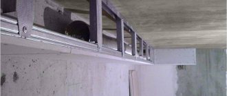
LED strips in the interior
As a rule, LED strips are used in the interior, in auto mechanics, instead of the main lighting in offices and factories. You can highlight furniture elements, a plasterboard box (special, now fashionable protrusions formed as decoration under the ceiling), a mirror with a simple pattern, etc. The backlight can be mounted in many different ways, emphasizing its aesthetics. Very often, LED is used to illuminate the ceiling. Lighting the ceiling with an LED strip creates a mesmerizing effect, giving the interior and all decorative items the necessary high cost. In many cases, your guests will not even understand where exactly the pure and diffused light is coming from.
Basic errors in connecting tapes
Mistake No. 1 – the security level of the tape is not selected correctly. For example, the use of boards with an IP20 rating is unacceptable in rooms with high humidity and in open spaces. When used in baths and bathrooms, a short circuit and electric shock may occur to a person.
Error No. 2 – the power of the power supply is not calculated correctly. It is important to follow the rule of 30% power reserve. This will allow in the future to connect additional sections or replace them with more powerful ones.
Mistake #3 – sequential connection of new sections. As mentioned above, each new tape is connected in parallel to the power source.
Error No. 4 – lack of heat sink elements. Tapes with a power of over 14 W are installed only on an aluminum profile, SDL with a power of 6 to 14 W are installed on metal tape. They perform the function of transferring heat from heating the crystals to the external environment.
Incorrect connection
Diagram of incorrect serial connection of two LED sections:
Diagram of incorrect (serial) connection of two tapes
The connection in series leads to an uneven glow of the tracks and overheating of the beginning of the tape. Therefore, each section longer than 5 meters is connected in parallel :
Example of parallel connection with 1 block and two
When the power of the tape section is above 9.6 V, it is recommended to make a parallel connection on both sides of the section. This guarantees a stable, uniform light output.
Example of two-way connection of a section
Incorrect mounting (location)
When installing, pay attention to the external environment. There should be no devices or factors nearby (within at least 0.6 m) that cause additional heating of the elements (heating system, incandescent lamps, kitchen heating appliances, sunlight, etc.). Optimal operating temperature is +40 0C.
The path for laying the SDL must be cleared of unnecessary objects. During operation, the board should not touch additional objects or have unnatural corners or bends (unless they are made by soldering or a connector).
Paper insulated power cables
- a popular cheap type of cable with its own disadvantages and advantages. Paper insulation is a non-uniform dielectric made of several layers of cable paper impregnated with an oil composition of varying viscosity - flowing or non-draining. The advantage of this type of cable is its relative cheapness and the ability to manufacture cables for high voltages. However, cables with paper insulation have significant disadvantages - the hygroscopicity of paper insulation and the limitation of installation on routes of different levels. To protect the insulation from moisture getting into the cable, the cable is enclosed in a metal sheath, and when the difference in levels between sections is more than 25 meters, cables with non-draining impregnating compositions based on ceresin are used. The most popular brands of power cables with paper insulation: SBL, SKl, TsSP
Advantages
The touch light switch has a lot of advantages.
- Easy to turn on and off the device by pressing the sensitive surface;
- Possibility of adjusting the brightness of lighting in a fairly wide range: 10–100%;
- No sound discomfort. When changing the operating mode or adjustment, the device makes virtually no sounds;
- High degree of protection. The switch is not susceptible to moisture. It can be safely installed not only in the kitchen, but also in the bathroom or toilet;
- Presentability. Modern models can become part of any interior, blending harmoniously into the surrounding space;
- Compactness. The devices are characterized by small sizes. This allows you to install the switch anywhere, including in confined spaces. Most often, the switch is mounted in the profile of the LED strip;
- Availability of light indication, allowing you to find devices in conditions of limited visibility.
Selecting a power supply and additional devices
You cannot plug the LED strip into a household outlet - it will burn out immediately. It is designed to operate at direct current with a voltage of 24 or 12 V, obtained through an appropriate pulse converter (power supply). The power of the device must correspond to the total power consumption of all connected tapes. For example, you need to connect three 5 m SMD-5050 reels with a power of 7.2 W/linear. m. The total capacity is:
5 m 7.2 W/linear m = 36 W
The power supply is selected with a margin of 20%, therefore, you will need a device with a power of at least 45 W.
The design of the block can be different:
- Sealed, compact unit in a plastic case.
- Sealed power supply in an aluminum case. Expensive, climate-resistant, often used in outdoor, street lighting.
- Open block in a perforated housing. The largest, inexpensive, requires additional protection from direct moisture. There are powerful models - one block is enough for all the illumination.
- Network power supply. Low power, up to 60 W, does not require installation. Multiple tapes will require separate power supplies.
The kitchen power supply must be moisture-resistant or installed in a place protected from moisture. It is desirable that the driver contains protection against voltage surges, which extends the life of the LEDs.
It is not recommended to connect LED strips in series, otherwise wear will be high and luminosity will be uneven. When connecting several tapes, it is correct to use an amplifier that provides uniform current supply to different sections of the electrical circuit.
If desired, the backlight can be connected via a dimmer - a device that smoothly reduces the power and luminosity of lighting fixtures. This way you can maintain the backlight in the “work” and “rest” modes.
To control the LED strip, PWM controllers are used that can provide the correct shape of the pulsating current to adjust the brightness of the LEDs
Amplifiers and dimmers are matched to the lighting system based on current strength.
Safety precautions
- All installation work is carried out with the power turned off.
- When installing the SDL on a conductive surface, the attachment point is pre-insulated.
- Observe polarity when connecting contacts; multi-colored conductors help with this.
- Do not touch exposed conductive parts while the power is on.
- Do not expose the board to mechanical stress (kinks).
- Follow electrical safety rules when working with 220 V networks.
- Related Posts
- LED dimmer 220V
- What types of LED strips are there and how to choose them
- Installation and connection of street road lighting