Motion sensors (hereinafter referred to as motion sensors) gained worldwide recognition in the 90s of the last century. With their appearance on the radio engineering market, universal devices solved the important problem of saving energy and significantly extending the “life” of lighting devices. Today, household infrared radiation detectors are widely used to illuminate local areas, entrances, staircases and premises for various purposes. However, devices may break during operation. Many novice home craftsmen are interested in how possible it is to repair a motion sensor with their own hands.
What you need to know and be able to do
Before you start repairing an electrical appliance, you need to check that it is working properly. To do this, you need to know its structure, the location of the component parts and the connection diagram. If the sensor was installed by the previous owner, then you should study the passport data. The documentation provides detailed instructions for installation and adjustment, as well as a diagram for connecting the device to the electrical network and the lamp. If there are none, everything can be found on the Internet under the DD brand.
Typical DD scheme:
Where are they used?
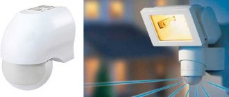
Devices such as LED sensor floodlight are very popular today due to their wide range of applications. Efficiency of operation with fairly compact dimensions, relatively low power, efficiency of diode lamps, it is also important that the connection diagram includes the installation of a motion sensor - these are the main factors that allow the use of this kind of lighting devices to illuminate large areas for any purpose.
Thus, lighting based on LED floodlights is organized in the border areas of the country, industrial facilities, warehouses, car parks and even in home areas. Street lighting can be organized not only using functional floodlights, but also using decorative lighting (directed or diffused light on the facade of the building).
How does an IR detector work?
The operating principle of an infrared motion sensor is based on recording changes in the density of thermal radiation in the controlled space using a Fresnel lens. As long as the infrared background of the room is stable, the sensor is in standby mode. As soon as a person enters the room, the level of thermal radiation changes the balance towards increasing the IR flux. This will cause a change in resistance in the lens, which will give a signal to the relay, which in turn will turn on the light. When the movements of people in the room stop, the reverse process will occur, and then the light in the room will go out.
Operating principle of the IR sensor:
What could cause a malfunction in the operation of the DD?
We need to find out why the problems arose.
This may happen after:
- voltage surge in the network;
- emergency shutdown and restoration of power supply;
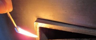
- the appearance of a burning smell;
- falling of the device on the floor;
- children's games (imbalance of adjustment screws, change in orientation of the sensor lens).
Correct viewing angle setting:
To identify the reasons why the motion sensor does not work, we will analyze it.
To do this you need:
- Remove the cover of the device (you will need a Phillips screwdriver).
- Then release all the wires from the blocks, remembering their original position. It’s better to take a sketch or photo on your phone.
- Next, conduct a study of the power and low-current boards.
Connecting DD via pads:
Disabling the motion sensor in the LED lamp. Help Wanted!
You are commenting as a guest. If you have an account, log in to write on your behalf. Note: Your post will require moderator approval before it will be visible.
ads
- Read before creating a topic!
Messages
Related publications
Good day everyone. During the renovation of the house I made a mistake - I purchased lamps for a regular dimmer with a twist - Legrand Valena Life, but they turned out to be non-dimmable. Disaster. A lamp from the JazzWay company, model PTR 2310, is installed on the track, the stated power is 10w. It itself is an aluminum cylinder with a radius of 8 cm and a length of 40 cm. When I realized what a mistake I had made, the first thing that came to my mind was to take it apart and see what was inside) It turned out that at the ends of this cylinder there was simply a plug and a stopper for the lens screwed into the thread. Under which I found a driver (probably that’s what it’s called) and an LED labeled LM002. I will attach a photo in the post. During operation, it will output 73V to the LED contacts. The power is 130mA, although I’m not sure about this because I don’t quite understand how to measure this correctly, at a line break or also with marks. (measurement was done on the LED marks as well as the voltage) Next question - What are the possibilities to convert the lamp into a dimmable one and what will the budget be? Is it possible to replace this power supply with a dimmable one without replacing the LED? Is it possible, for example, to purchase a light bulb with a similar or matching LED and replace the board or the whole thing while maintaining the standard locations?
I ask for help from people who understand this topic))) Help
Tell me what's the matter. There is a spotlight with LED lights, 3 of them burned out and it did not work. I removed 1 light and put a jumper in its place, it worked! But the resistors in front of the DB157 diode bridge heat up in a couple of seconds. 2 have already come out and when I was building I replaced them with the same rating but 1 watt and not 0.5 as it was. Instead of a jumper, I installed a 1K resistor, it lit up, but the resistor quickly began to heat up and had to be opened. If instead of all 3, installing jumpers will help?
Hello. Radio ruined on the air. Long time no see. Here it is, such a thing. It means the driver from Alika for LEDs has arrived. I'm making a homemade lamp for the radio room. Here he is in the picture.
Power - 30-50 W. Produces a current of 480mA. That for my 3-watt 5730 diode assemblies is a big deal, I need at least 300mA, and better yet 280mA. Well, actually, there are parallel current-setting resistors, these are rs1 - 1.5 ohms, rs2 - 1.8 ohms, and for rs3 rs4, respectively. In total, the resistance is somewhere around 0.8 ohms. I connected two assemblies in series and an ammeter in the gap, turned it on, the driver started up, the assemblies lit up very brightly, the current is really 480 mA, I think about the horse heating of the assemblies literally in seconds from such a current it is unnecessary to say. This means you need to reduce the current. To begin with, I simply unsoldered rs2 and rs4, which are 1.8 ohms each. The final resistance became 1.5 ohms. I connected it to two assemblies, the current output was 270 mA. Just what I needed, I thought. Connected 15 LED assemblies. I turned it on, and the diodes glow weakly, the current is 125mA. I unsoldered one assembly, connected it again, the current is higher, it shines brighter, but still weak. I soldered another one, better, but not enough. More. And now minus 3 assemblies, it shines normally at a current of 270mA. I would like to power all the diodes. Driver power allows. 3V for 15 assemblies we get 45W of power. I started trying to select the total resistance of the current-setting resistors. I soldered back the soldered 1.8 ohms - I connect them, all 15 pieces shine brightly, but the current is 480 mA. I soldered in a 3.3 ohm resistor instead of 1.8 ohm. All diodes are shining. The current dropped to 350mA, which is also too much. Soldered in 5.1 ohm. And this is where things started to get interesting. When turned on, the current starts at 170 mA and begins to grow slowly, the assemblies blink, the growth lasts about half a minute and reaches 315 mA. I started looking for why this is so. On Alika, one person wrote a detailed review and mentioned that: “S9268D microcircuit. When selecting resistors, the driver may not start, the lamp will blink, in this case it is necessary to select “setting resistors R3 and R4.” Well, that’s my case, I thought. Just in which direction and what denomination should I choose them? Unfortunately this was not said. Here's a video of how it all happens. What will the local pros say?
Visual-tactile diagnostics
Repair of motion sensors may be limited to identifying damaged radio components and replacing them as a result of visual-tactile diagnostics of the infrared sensor. The device is disassembled and placed on the desktop under the light of a table lamp, armed with a magnifying glass: Check the integrity of the radio elements. There should be no swollen containers, darkened, cracked or loose elements. The smell of something burning will indicate the presence of burnt parts. They are clearly visible on the board.
The board track may burn out. Cracked, burned and broken grooves are restored by soldering jumpers. Analysis of the breakdown will help to avoid further malfunctions in the detector.
Troubleshooting:
It is necessary to check the soldering of all radio elements. A tactile inspection reveals poorly secured elements on the board, and they are soldered again. All suspicious parts are replaced with new elements.
Common malfunctions and how to eliminate them For motion sensors for lighting, the most typical manifestations of operational failure can be characterized as follows:
- The lamp does not turn on.
- The sensor does not turn off the light.
- False alarm.
- Sensor orientation is incorrect.
Another addition
On February 10, my reader Mikhail sent a photo of the sensor (see the comment for this date), in which the resistor on the board burned out when turned on:
Chinese motion sensor with a burnt resistor on the board
If anyone has such a sensor or its circuit, help Mikhail and tell him the resistor value. Thank you in advance!
I’ll add that the resistor just doesn’t burn, this is a consequence! 90% that after replacement it will burn again!
The lamp does not turn on
If the DD does not turn on the light, then you need to check the current flow to the low-current board. This is easy to do using a tester. Having made sure that there is voltage at the input of this circuit, move on to the tuning regulators. Typically, there are three screws on the device body with the following symbols:
- SENS - it regulates the sensitivity of the pyro receiver;
- TIME — sets the delay time for turning off the lighting;
- LUX - sets the threshold for the level of illumination.
IR detector settings screws:
The device is connected to the network and to a 40-60 W lamp. The adjusting screws are brought to the extreme maximum position, gradually decreasing the values of all three adjustments. This achieves optimal operating conditions. You can adjust the settings in the opposite direction from the minimum values.
Adjustments on the ceiling detector body:
If there is no response from the device, check the power supply to the power circuits. They test the relay, that is, establish the presence of voltage on its coil. For safety reasons, the test is carried out with the low-current board completely disconnected. Next, they close the base with the emitter of the transistor and make sure that it is closed, while the relay should be turned off. The base is connected to a constant voltage through a resistor, and the transistor should open and the relay will operate. If none of the above processes occur, then the transistor must be replaced.
Test run
Connect power to the sensor. I recommend using an incandescent light bulb with a power of 25-60 W as a load to indicate the operation of the sensor. Otherwise, if you focus on the clicking of the relay, you may not hear or understand whether it is on or off. Now we check the relays and connections.
I highly recommend turning on any devices during repairs through the minimum possible circuit breaker. In this case - 1-2 Amperes. This is necessary to avoid troubles.
A better option is to connect through a transformer (with an output voltage of 220V) or a difavtomat, this will significantly reduce the risk of electric shock (we will work with open live parts!).
Another option is through a 60-100W incandescent light bulb, this will save you from a short circuit. But it's not convenient.
I recommend your article on the use of circuit breakers.
We check that the required supply voltage is present on the power board.
I won't tell you how to use measuring instruments or how to check parts. If you have questions, write in the comments.
In addition, I urge you to be careful and remember your safety! During repairs it may get fucked up!
Once again we return to where we started the repair (point 1). There is a high probability that after inspection, soldering, and replacement of visually faulty parts, everything will work.
The sensor does not turn off the light
In this case, first turn to adjusting the settings. You can try to repair the sensor by adjusting the SENS and TIME screws. Due to incorrect settings of these parameters, the lighting may not go out. The fact is that if the rotary lever is set to the extreme right position, the relay will stop opening the power supply circuit of the lamp.
Pyroelectric sensor:
Violation of the DD operating mode may occur due to the appearance of residual load. Then the functionality of the device is restored by disconnecting it from the power supply for 10-15 seconds. If this is the reason, the sensor will work in its original mode. If the detector still does not turn off the light, check the operation of the relay. If a defect is detected in this part, it is replaced with a new device.
Checking the power
In the motion sensor, the 220V input power is converted into DC voltage required to power the circuit. As a rule, these voltages are 8, 12, 15, 24 V in different combinations, depending on the circuit.
All voltages are measured relative to zero. The point where you can take a zero - for example, the minus of an electrolytic capacitor at the output of a diode bridge.
In this case, you first need to check the +24V voltage (see diagram at the beginning of the article). If it is not there, you need to check the limiting (quenching) elements in front of the diode bridge, and the diodes themselves.
It is possible that the subsequent circuit “extinguishes” or adds power. To verify this, you need to disconnect the subsequent circuit from the power supply circuit.
We also check the low voltage +8V, which is used to power the operational amplifier circuits.
If it is not there, we check the circuits before it (presence of +24V), the stabilization circuits (zener diode), and test disconnect the load.
False alarm
Over time, the infrared sensor can take on a life of its own. Regardless of whether there is movement in the room or not, it automatically turns the lights on and off. False positives can be caused by both direct and indirect reasons. These can be powerful heat flows emanating from various heating equipment, or jets of cold air from air conditioners. Therefore, when installing the device, you should avoid close proximity to ventilation and air conditioning systems. The multilens should not be exposed to direct sunlight, which can interfere with the detector settings.
Operating principle of the IR detector:
Excessive cluttering of the viewing area of the device with furniture or other large objects can cause involuntary switching off or, conversely, switching on the lighting. Also, the increased sensitivity of the DD will cause it to be triggered by the movement of pets and even flying parrots. To prevent this from happening, the sensor is installed in the place of maximum access to the entire internal space of the room and the sensitivity level is reduced by turning the SENS screw counterclockwise.
Adjusting the device
Fine tuning of the sensor is carried out using the available regulators, each of which is responsible for the corresponding option:
- SENS – determines the sensitivity of the device. With its help, you can set the size of the object that the sensor will respond to and the distance to the detected source of motion. In this way, it is possible to reduce the number of false alarms when a small animal enters the field of view, or an object moves outside the controlled area.
- TIME – adjusts the duration of operation of the lighting device after activation. It is recommended to set the parameter for at least 2 minutes to prevent frequent operation.
- DAY LIGHT – allows you to select the time to turn on the lighting devices. Options available include night mode or 24-hour monitoring.
The type of fastening and design of the sensors are characterized by mobility, due to which the position of the device in space can be adjusted in four directions - up or down, right or left. Thus, it will be easy to configure the device to monitor a selected area of the territory, experimentally achieving its maximum coverage.
Incorrect sensor orientation
In the accompanying documentation of the motion sensor, the manufacturer usually indicates the orientation of the motion detector in the space of the room. The horizontal device is made in the form of a volumetric toroidal disk, which is attached to the ceiling. The DD review is 3600. Its installation is quite simple and does not cause any difficulties.
Horizontal sensor:
Corner and wall modifications require proper orientation. If the room has two doorways in adjacent walls, then install corner models. In other cases, the device is hung on one of the walls, but not opposite the windows. Direct sunlight can have a detrimental effect on the condition of photocells. Incorrect setting of the DD can create “dead” zones where the device will not respond to the appearance of a person. Therefore, you need to spend some time walking around the room while tilting and turning the head in order to obtain the optimal detection range and range of the device.
If the room is an L-shaped room or corridor in plan, then it is advisable to install two sensors. They should be turned as close as possible to each other so that there are no “dead” zones. It is also important that the luminaires are kept out of the detection range. The light flux should not fall on the multilenses of motion detectors.
When purchasing a motion sensor for lighting, it is better to pay attention to branded devices and not go for cheap ones. High-quality sensors will not cause short circuits and will last for decades. If you lack experience and knowledge of radio engineering, then it is better not to undertake repairs yourself, but to have the broken device repaired by professionals.