A broken switch is an unpleasant situation that requires a quick solution. In order not to wait for an electrician to arrive and quickly restore the lighting, it is advisable to be able to repair the device yourself. Agree, this is not only convenient, but also practical from a financial point of view.
The design of the device is not particularly complicated, so repairs are accessible to almost any home craftsman who has at least a little experience in handling electrics. First you need to figure out how to disassemble the light switch, and then determine the cause of the breakdown and fix it.
We suggest you understand the specifics of dismantling keyboard, rotary and touch models, as well as find out the most likely reasons for the failure of the switching device.
Types of switches and operating principles
Based on the number of switched chains and the number of keys, all existing types of switches are divided into the following types:
- single-key models;
- two-key samples;
- three-key devices.
Another type of old device is still in use, in which the element that controls the switch mechanism is more like a button.
In addition, rare types of rotary-type switching products are presented on the domestic market. In terms of control method, they are a bit like a packet switch. There are also inexpensive Chinese devices related to touch sensitive devices. To control them, you don’t need much effort - just put your finger on the contact plate.
The operating principle of a conventional type switch is based on the closure of the moving and fixed contacts when the key is moved to the upper position and their opening when the reverse action occurs. The so-called “pass-through” switch works in the same way, differing from the usual one in the presence of additional groups of contacts, as well as in the method of inclusion in the lighting network.
Causes of breakdowns
A faulty switch can be determined by the following signs:
- when you press a key or turn a toggle switch, knob, or other actions, the light does not turn on;
- turning on or off operations require multiple repetitions, keys or other elements work with jamming;
- an increase in the temperature of the light switching device housing is felt;
- after the circuit is closed, a crackling sound is heard or the lamp flickers;
- frequent burnout of light bulbs, regardless of their type (incandescent, LED, halogen, etc.);
- when the contacts in the switch close, a crackling sound is produced;
- The device does not connect to the network.
These problems may occur due to the following faults:
- Destruction of individual elements of the switch or melting of contacts.
- Violation of integrity and contact in the place of fixation of electrical wiring or terminals.
- The housing in the contact group is destroyed.
- The contact group is worn out.
The basic principle of operation of any type of switch is that it closes to turn on the light and opens the contacts to turn it off. However, often in more complex switch configurations, breakdowns can be even minor, which will prevent the luminaire circuit from closing.
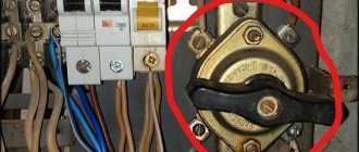
Connection diagram for PV cables in the distribution box
Schemes for installing a changeover switch
An important step is assembling the circuit of the pass-through switch in the distribution box. 4 wires with 3 cores go to it - a power cable from the automatic light control from the switchboard, a cable to the 1st and 2nd switch, a cable to the light source.
During the work you need to focus on the color of the wire:
- phase – white/gray;
- zero – blue/brown;
- earth – yellow-green/black.
The assembly provides the following step-by-step algorithm:
- Connection of the neutral core coming from the input cable of the machine and the neutral wire going to the lamp with terminals.
- Connecting all earth conductors in the presence of a grounding conductor. The ground from the input is thrown onto the outlet ground using terminals.
- Ground connection to the housing of the lighting device.
- Coupling the phase from the input cable with the phase from the outgoing cable and fastening them to a common terminal in the 1st switch.
- Connection of the common wire of the 2nd switch with the phase of the lighting cable terminal.
- Connection of secondary outgoing conductors of switches No. 1 and No. 2.
- Applying voltage and testing the design.
Disassembling the light switch
To repair a switch, you must first disassemble it. Let's get to work. Even though you have already turned off the power supply, check the voltage level using a multimeter. If you do not have such a device, use an indicator screwdriver, which you can purchase at your local hardware or electrical supply store.
Two-gang switch
- When starting to solve the problem of repairing a light switch, arm yourself with a thin screwdriver or knife in order to pry and remove the buttons, as well as the decorative cover of the switch from a special plastic box (socket box). New models usually have a recess to make it easier to lift the lid. Then you need to unscrew the screws located under the buttons. Don't forget to carefully place them in the prepared container.
- Remove the switch from the wall by unscrewing the fasteners, not forgetting to mark its position on the wall. Fastening elements may be different, depending on the material from which the wall is made.
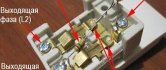
- With a marker, mark the main wire attached to the main terminal, which is responsible for the voltage.
We are preparing
Before connecting the switch, it is necessary to prepare it for installation. We will discuss how to do this below.
Remove the key by prying it in the center on the left or right side with a flat-head screwdriver.
Unscrew the two screws located diagonally.
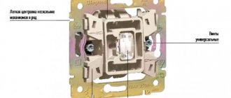
Now the mechanism is available to us. The mechanisms of single-key switches can be of different designs, but they have the same connection principle. There must be two contact clamps and spacer tabs for attaching to the socket box.
In our mechanism, the screws of the spacer legs are located on the left and right.
They set the metal fixation claws in motion.
And two contact screw clamps for connecting wire cores.
By unscrewing or tightening the contact screw, we move the pressure plate, designed to securely fix the core in the contact.
Each contact provides connections from 1 to 2 wires.
Restoring rotary and touch models
Touch switches must be repaired in specialized workshops. In rotary-type devices, characteristic malfunctions have approximately the same causes and manifestations as in keyboard analogues. In their working mechanism, the closing and breaking contacts also burn out and completely wear out, which is explained by their intensive use. In addition, by analogy with the samples already considered, it is also possible for them to loosen the contacts at the points where the phase conductors are connected.
Restoring switches of this class is similar to the approach already discussed for key products. Difficulties arise when the cam mechanism breaks down, which is unlikely to be repaired manually. In this case, experts advise completely replacing the device with a new product.
Touch switches at home cannot be repaired. Due to the complexity of the design of the dimmer device, their restoration is possible only in specialized workshops.
Extension cord repair
Households often use extension cords to connect electrical appliances located at a great distance from outlets. They are produced in the form of surge protectors equipped with a switch for several outlets.
Dismantling
To find the breakdown, you will need to unplug the extension cord and disassemble it. Determine the location of the problem: block with socket, cable or plug. If it is impossible to determine the defect immediately upon inspection, the extension cord must be disassembled. All operations are performed according to the following algorithm:
- There are screws in several places that hold the top cover on a flat base with the wire and socket cores.
- It is necessary to unscrew all the bolts with a screwdriver.
- Place the screws in a separate container so as not to lose them during repairs.
- Unscrew the copper plates that come into contact with the wires.
Replacement and repair of parts
Depending on the problem, there may be several ways to repair the extension cord:
- If the wire is broken, look for the place of bad contact. To do this, connect an extension cord to the network, insert a table lamp or other device into it, which will signal the presence of current in the circuit with sound or light. The wire must be bent in different directions every 5 cm and see at what stage the connected device lights up or starts playing. This place must be carefully cut out, the wires exposed, soldered or twisted in pairs, and wrapped with electrical tape separately from each other.
- If the problem is in the plug, then most often a replacement with a new one is required, since cutting it and looking for the problem is a more expensive undertaking than replacing it.
- If the problem is inside the case with the extension cord sockets themselves, first check each of them for contact of the wires with the copper plate. If it is bad or missing, you need to wipe all contacts with a file. Most often, this operation corrects the problem. The plates must fit tightly to the fork, so you need to bend them in the right direction.
Assembly
After repairing the device and preliminary checking its functionality by restoring the current supply, you should install it in its place and assemble its parts in the reverse order. There shouldn't be any particular difficulties in this matter. However, if you still have doubts, you can use the photographic material that you prepared for yourself in advance (even at the disassembly stage). Having started assembling the switch, you first need to connect the wire that we previously highlighted with a marker to one of the terminals, and after that all the remaining wires. At the next stage, the device is fixed in the socket box and the housing rim, decorative cover and light on/off buttons are installed.
At this point, the process of repairing a switch at home can be considered complete.
By following safety precautions and the above tips, acting step by step and with due care, you can extend the life of the switches in your home without much effort and without the help of strangers.
Repair procedure
So, your switch doesn’t work, you decided to repair it yourself and have already prepared the necessary tool. Now let’s move on directly to the repair, which will be easier for you to complete using these step-by-step instructions:
- To prevent electric shock during work, first of all, you need to de-energize the apartment by unscrewing the electrical plugs or turning off the switch.
- Make sure there is no voltage by checking any household outlet with an indicator screwdriver.
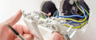
- Remove the light switch. To do this, you need to remove the decorative cover, additionally check with an indicator screwdriver that no current is supplied to the device, and then unscrew the side fastening screws. Now the body of the device can be pulled out of the socket box.
- Separate the electrical cables from the light switch. If the device has two keys, it is advisable to mark the input wire with a marker, otherwise they can be confused when connecting them back.
- Disassemble the body. This opens up access to the contacts, which are usually the cause of breaker failure. They are located under a plastic key fixed with screws.
- Perform a visual inspection of the contacts. If carbon deposits are found on them, remove it with sandpaper to restore the metallic shine.
Sometimes carbon deposits cannot be completely removed with sandpaper. In this case, the remnants of it must be removed with the tip of a slotted screwdriver.
The repair procedure is now complete. Now you should reassemble the switch in reverse order. To avoid confusion, you can use photographs that were taken during disassembly of the product.
Basic requirements for work on replacing electrical equipment
There are a number of requirements for carrying out repair work on electrical equipment. Their implementation will ensure the safety of the entire work process.
- The main requirement when working with electrical equipment is to de-energize the object on which the switch must be installed. To do this, either independently or with the help of a specialist, turn off the electricity from the meter or switchboard.
- After de-energizing the room, it is necessary to check the lack of electricity using a voltage indicator (indicator screwdriver) or a control lighting device (control).
- Next, the old equipment is dismantled and new equipment is installed.
It is important to take into account that each installed device partially differs in installation principle according to its distinctive features
Switch installation
Having assembled the switch, we proceed to installing it in its original place. First of all, the input conductor marked with a marker must be connected to the common terminal, and then the remaining cables. After this, the device must be secured in the electrical outlet. Lastly, the housing frame and cover are installed.
Sometimes it is not possible to install the cover on the switch base. The reason, as a rule, is the incorrect position of the device body inside the socket box. It is necessary to loosen the fixing bolts with which the switch is held in the plastic box, and, having placed the device body in the desired position, tighten them again. If the product is in the correct position, the lid will easily fit into place.
Connection to the power supply system
You can determine that the electrical wiring was carried out according to the new system by looking at the laid cable. It will be three-wire for single-phase power supply or five-wire for three-phase power supply. One of the single-phase power wires will be the phase marked in brown or red, the other will be the neutral (zero) marked in blue, and the third will be the protective wire marked in yellow-green.
To facilitate identification, alphabetic and color designations are used:
- A, B, C - phase;
- N - neutral or zero;
- PE - protective.
The difference between this connection diagram is the additional protective conductor PE, which is led directly to the lamps.
The connection diagram for electrical installation devices TN-S assumes connection to a grounding system
After connecting the wires to the working mechanism, they are pressed closer to the body and then installed in the socket box. Fixed in the mounting box using clamping tabs or bolts. Put on the decorative case and keys.
Before assembling the entire structure, turn on the light and make sure the lighting system is working
Basic troubleshooting methods
Most often, when the device is turned on, the contacts burn out, and here it is recommended to simply clean the contact groups. It is better to do this with a small piece of sandpaper. Sometimes the switch does not work due to loose wire clamping, so it is necessary to check the functionality of the fixing screw.
The heavy operation of the switch, especially with the sliding type of contacts, is due to the fact that there is no lubrication, because of this the contact does not turn on the chain. The presence of melted plastic or crumbled ceramic housing means that the device is completely broken and must be permanently replaced.
Practical advice
- If an old-style switch breaks, you can of course fix it, but there is no point in doing so, because... Every part wears out over time, and in electrical work it is very dangerous to use old switches and sockets, especially if they often break down. Today, even such leading companies as Legrand have inexpensive but reliable products, even with lighting, a chain (cord) or a dimmer.
- The reason why the contacts on the key switch burn out quickly is because the light bulbs are too powerful. We recommend replacing incandescent lamps with more efficient and at the same time less powerful light sources - LED lamps. In this case, you can forget about repairing the switch for a long time.
- Before proceeding with complete disassembly of the case, check how well the wires are tightened with screws. You may be able to fix the switch simply by tightening the screws with a screwdriver.
- In order not to confuse the order of assembly of spare parts of a disassembled case, we recommend using a camera: take photographs of each of the disassembly stages one by one and, if necessary, assemble the structure from the photo.
That's all I wanted to tell you about how to fix a light switch with your own hands. We hope that the provided instructions and photo examples will help you repair a switch that does not turn off or turn on the lighting in the house!
Step-by-step instruction
Let's look at how to change the switch.
Preparatory stage
The main thing when working with electricity is safety. If you lack confidence in your own abilities, it is recommended to use the services of a professional electrician.
If you decide to do the work yourself, follow these preparatory steps:
- The lack of light is not caused by problems in the electrical network, but by a burnt-out cartridge. Checking the cartridge.
- Let's see if there is light in other parts of the house (apartment).
- If, based on the results of the check, there are no malfunctions not related to the electrical network, we proceed to dismantling the switch. Before changing the switch, we turn off the power to the apartment. To do this we use a switch. We check the mains voltage with an indicator. We inform family members about the renovation work. No one should use the light while the switch is being replaced.