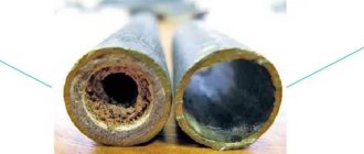
Currently, most residential owners prefer to use warm water floors for heating. The efficiency of this design depends on proper coolant flow.
Adjusting the flow meter of the underfloor heating manifold will allow you to monitor water consumption in the pipeline and fine-tune the system.
This device can facilitate the balancing process and rationally distribute liquid over the heating circuits, thereby creating uniform heating of all rooms.
The essence of the collector
The main feature of a water heated floor is the coolant; the water gradually moves to the heating circuit and gives off part of its energy.
That is why the heating of the floor occurs with the release of heat to the air that is mixed inside the room, and it, as is known, is directed from the bottom up. A number of devices are responsible for supplying warm water to the circuit and intensity:
- the valve is considered the main one;
- a pump must be present;
- collector.
All control of water distribution is carried out using a flow meter. It is this device that plays the main role in the operation of the entire system.
All collectors are designed specifically for hot water, and they are also necessary to collect waste material. In the unit itself, the process of mixing hot water that comes from the source and return takes place.
Thanks to rotameters, there is a chance to ensure that the entire volume of water reaches the floors. Simply put, the equipment will independently control the heat in the water field.
Floor heating cannot do without a rotameter. The design includes a body made of plastic, but there are models made of brass. A float is placed inside any device. There is a flask with a scale.
The float can move up and down and at the same time points to a certain division of the scale. Judging by it, it will be possible to judge the volume of coolant that circulates in the pipeline.
If we talk about theory, the system works without a device, but in this case the adjustment has to be done manually, relying on your own sensations.
The flow meter for the underfloor heating manifold plays an important role; if it is abandoned, the following problems will arise:
- the fact is that in the absence of a flow meter, some floor contours can be supplied with coolants, while the features of the room will not be taken into account;
- the energy consumption used to operate heating devices, for example, either gas or electricity, will be excessively increased.
Let's say you plan to simultaneously heat the bathroom and another room, for example, a bedroom. A gas-powered boiler will heat water for the bathroom and bedroom absolutely identically, that is, there will be one temperature regime.
It is important to install the equipment correctly; to do this, you need to screw the device itself into the collector socket. Fixation occurs due to the nut. When improving a heated floor, it is advisable to try to control the length of the heat pipeline of all circuits, without paying any attention to the configuration. This will simplify the adjustment of the system and it will still be possible to achieve normal temperature parameters.
But we must take into account that the bathroom is small in size, in order to heat it you need less water from the boiler, but more water is required to supply the bedroom. It is possible to compare the heat of each room, but only in this case will you need to use a flow meter.
If you use this device, the temperature will be set in the bathroom and bedroom for a comfortable stay there.
Having carefully assessed the principle of operation of this device, we can draw the following conclusions:
- the device can function completely autonomously, without the need to use any additional power sources;
- the main operating principle of the flow meter makes it possible to sufficiently consume the coolant for the circuit and further significantly reduce the energy costs of all heating devices;
- the design of the entire device is capable of providing control over the amount of water entering the pipes;
- the manifold, which is installed together with the flow meter, makes it much easier to control the operation of the entire system in general. Also, installation of the system is not complicated and does not require special maintenance.
Results
It is important to ensure that when the water floor heating system is operating, the flow rate on the collector is visible. This is necessary for maintenance. Each water circuit must have its own flow meter.
We recommend: How to choose a thermostatic valve for underfloor heating?
As you can see, in the equipment, each element performs its own functions, so each one needs to be given sufficient attention, and in order for the entire system to work as one whole, it is worth equipping it with a flow meter and a collector, which will evenly distribute all the heat.
- Related Posts
- How to choose a boiler for underfloor heating?
- What is the pipe consumption for underfloor heating per m2?
- How to install Q-Term heated floors?
- How to check a heated floor?
- Features of Fenix heated floors
- How to install a Devi heated floor?
Purpose and types
A warm water floor is distinguished by a large number of pipe circuits and a low temperature of the coolant circulating in them. Basically, heating the coolant to 35-40°C is required. The only boilers that can operate in this mode are condensing gas boilers. But they are rarely installed. All other types of boilers produce hotter water at the outlet. However, it cannot be run into the circuit at this temperature - a too hot floor is uncomfortable. To reduce the temperature, mixing units are needed. In them, in certain proportions, hot water from the supply and cooled water from the return pipeline are mixed. After which, through the manifold for the heated floor, it is supplied to the circuits.
Manifold for underfloor heating with mixing unit and circulation pump
To ensure that all circuits receive water at the same temperature, it is supplied to a heated floor comb - a device with one input and a number of outputs. Such a comb collects cooled water from the circuits, from where it enters the boiler inlet (and partially goes to the mixing unit). This device - supply and return combs - is also called a manifold for heated floors. It can come with a mixing unit, or maybe just combs without any additional “load”.
Doppler method
Counters operating using this method measure the difference in wavelength reflected from a moving stream relative to the wavelength of the emitted signal. Measuring the received and transmitted signals to determine the difference between them is done using wedge-shaped or pipe speed sensors installed at the bottom of the channel or pipe.
Water meters operating on the Doppler effect are used in pressure and gravity systems, fully and partially filled pipes, and open channels. They work in streams of varying degrees of pollution (except clean water). Doppler flow meters are used for commercial metering in pipelines and gravity canals, for measuring flows in rivers and canals of irrigation systems, in storm sewers, at pumping stations, water intake pipelines and discharge of wastewater into reservoirs.
How does the collector work?
Water floors are laid in various ways, for example, concrete or flooring, but regardless of the technology chosen, it is necessary to purchase and install a manifold cabinet.
In the future, two pipes will be inserted into it:
The cyclical nature of the process is ensured by another built-in component of the system - a circulation pump. One way or another, during the operation of a heated floor, say during repair work, the system has to be turned off. To do this, each of the pipes is equipped with shut-off valves. A plastic pipe and a metal shut-off valve are connected to each other through a compression fitting. Then a comb is connected to the valve, mounting an air vent on one end and a drain valve on the other. After assembling the cabinet, they proceed directly to installation. And only with a comb already installed on the wall can you cut the circuit pipes to length.
Tags
Heated floor heated floor heated floor vaulted floors. heated floor. has a polypropylene float, it has full control and is polycarbonate. This position will allow the circuit completely or Warm floor Adjustment of heated floor heated floor collector coolant flow. heated floor collector. adjustment of coolant by volume of coolant you need you need a flow meter or Flow meter device install a flow meter with flow meters and clean the flow meter adjusting the manifold flow meter You need a flow meter or a flow meter device a group of flow meters running in the flow meters in
than control the sensor
Warm floor and the space occupied by the manifold with flow meters
The peculiarity of a heated floor as a heating system is that the heated coolant, moving along the heating circuit, transfers part of the thermal energy to the floor surface. Thus, by heating the floor, heat is transferred to the air mass circulating inside the room in the direction from bottom to top. A number of devices control the supply of warm water to the heating circuits, the intensity and flow rate, including:
- three-way valve;
- circulation pump;
- collector.
The distribution of the coolant is controlled by a flow meter for heated floors. This device plays one of the key roles in the operation of the entire pumping and mixing group. Heated floor collectors are designed to supply hot water and collect waste coolant for its further use in the heating system pipeline. In the pumping and mixing unit, hot water coming from the heating source is mixed with the coolant returned to the circuit - return. The functionality and efficiency of heated floors is based on this operating principle.
Mixing unit with rotameters for a warm water floor system
Together with the operation of safety valves, rotameters are designed to regulate the temperature of the coolant in individual circuits of the water floor. Thanks to these devices, the required volume of prepared water entering the warm water floor system is ensured. In other words, this equipment monitors the amount of coolant in the water heating pipe, and therefore the functionality of the entire heating system.
Is a mixing unit necessary?
A legitimate question, especially considering the decent cost of the collector. It should be recognized that water heated floors without a mixing unit can work normally, but only if they have one heating circuit. What does this mean in practice?
According to the manufacturer’s recommendations, the length of the pipe to be laid in heated floors should not exceed 70 m. Considering that with a maximum gap in the pitch between the pipes, this amount will only be enough for 7 m², it is not difficult to calculate; to heat a medium-sized room, three circuits will need to be laid at once.
In most cases, heated floors are installed for several rooms at once: hallway, bathroom, kitchen, etc. It is unrealistic to ensure a uniform supply of coolant without connecting to the boiler room manifold. But if you need to heat only one small room, then you can do without a mixing unit.
Installation without a collector has several disadvantages, including: the supply of coolant with a temperature identical to that in the general heating system, the impossibility of automatically removing air pockets and controlling pressure.
This is interesting: Which floors are better to make in a private house - we outline it point by point
Typical connection diagrams
Water heated floors are rarely used as the only source of heating. Heating only due to underfloor heating is permissible only in regions with a mild climate, or in rooms with a large area, where heat removal is not limited by furniture, interior items or the low thermal conductivity of the floor covering. Almost always it is necessary to combine radiator circuits, hot water preparation devices and underfloor heating loops in one heating system.
Typical diagram of a combined heating system with connection of radiators and underfloor heating circuits. This is the most technologically advanced and easily customizable option, but it also requires significant initial investment. 1 - heating boiler; 2 — safety group, circulation pump, expansion tank; 3 - manifold for separate two-pipe connection of radiators in a star configuration; 4 — heating radiators; 5 - underfloor heating manifold, includes: bypass, three-way valve, thermostatic head, circulation pump, combs for connecting underfloor heating circuits with gearboxes and flow meters; 6 - heated floor contours
There are quite a large number of variations in the design of the boiler room piping, and each individual case has its own principles of operation of the hydraulic system. However, if you do not take into account very specific options, then there are only five ways to coordinate the operation of heating devices of various types:
- Parallel connection of the underfloor heating collector to the main line of the heating unit. The insertion point into the main line must be made up to the connection point of the radiator network; the coolant supply is provided by an additional circulation pump.
- Association according to the type of primary and secondary rings. The line, wrapped in a ring, has several supply connections in the supply part; the coolant flow in the connected circuits decreases with distance from the heating source. Flow balancing is performed by selecting the pump supply and limiting the flow with regulators.
- Connection to the extreme point of a coplanar manifold. The movement of the coolant in the heated floor loops is ensured by a common pump located in the generator part, while the system is balanced according to the principle of priority flow.
- Connection through a hydraulic separator is optimal when there are a large number of heating devices, a significant difference in flow rates in the circuits and a significant length of underfloor heating loops. This option also uses a coplanar manifold, but the hydraulic arrow is necessary to eliminate the pressure drop that interferes with the correct operation of the circulation pumps.
- Local parallel loop connection via unibox. This option is well suited for connecting a short-length heated floor loop, for example, if you need to heat the floor only in the bathroom.
The simplest option is to connect a heated floor circuit to a radiator heating system with a coolant temperature of 70-80 °C.
1 - line with supply and return of the high-temperature circuit; 2 - heated floor contour; 3 - unibox. It must be remembered that the nature of the operation of a heated floor may also change depending on the installation pattern of the coil. The “snail” scheme is considered optimal, in which the tubes are laid in pairs, which means that the entire area is heated almost evenly. If the warm floor is arranged as a “snake” or “labyrinth”, then the formation of colder and warmer zones is practically guaranteed. This drawback can be eliminated, including through proper configuration.
Cross-correlation ultrasonic counters
Such flow meters operate using the ultrasonic signal cross-correlation method. This technique is based on the principle of constructing velocities at different flow levels; the meter makes it possible to construct a real diagram of the distribution of velocities in the flow. The flow level is also measured.
Ultrasonic pipe and wedge-shaped speed sensors installed in the flow are used with water meters; the liquid level is determined using surface and underwater sensors. It is possible to design combined speed and level sensors.
Meters are used in pressure and gravity, open and closed systems. This is an accurate measurement method that gives reliable results for flows of varying degrees of contamination, including it is effective in heterogeneous media. Flow meters are used in process pipelines, wastewater treatment plants, rivers and reservoirs, etc. In large channels, several sensors can be installed across the entire width to obtain more accurate results.
Why do you need a flow meter?
Theoretically, it is quite possible to do without installing a flow meter in the manifold. However, if you do not install this device, then:
- Different rooms will have different temperatures;
- There may be excessive consumption of electricity to heat water in the system;
- Different circuits will heat up unevenly.
A simple example can be given: a bathroom and a bedroom. A gas or electric boiler heats water equally for both the bath and the bedroom. But the bathroom is at least 3 times smaller in area than the bedroom. Accordingly, the bathroom will be hot and the bedroom will be cool with the same water supply to the floor heating system. This situation is due to the fact that in the bedroom the total length of plastic pipes in the area is much greater. It is precisely in order to regulate a comfortable temperature in the entire apartment that it is desirable to install such a device.
Advice! When installing a water heated floor, you should strive to make the contours of the pipes approximately the same length. This will save energy costs and allow you to more accurately regulate the temperature.
Principle of operation
The device is installed on the return collector outlets. When the set temperature in the system is reached, the manifold valves narrow the lumen of the energy supply or close it completely. This principle of operation is possible with full automation of the system. For this purpose, the collector is equipped with a temperature sensor.
The flow meter itself consists of several parts:
The flask is usually made of durable glass; the body can be plastic or brass. The float is located inside the flask; it serves as an indicator of the coolant speed. The flow meter is also called a float rotameter.
In an automatic water heated floor collector, balancing of coolant flow is carried out using a temperature sensor. If the latter is not provided, then the rotameter can be adjusted manually.
Control elements
Setting up a heated floor collector is impossible without special devices. With their help, the optimal heating mode of the system is established and water flows in the pipelines are regulated. Each of them performs a specific function.
- Water temperature sensor
Installed on the inlet and outlet pipes of the device. These devices do not affect the operation of the system, but indicate the current heating rate. The difference in values can be useful in calculating operating efficiency. They also serve as an indicator of heating mode violations.
- Central thermostat with servo mechanism and sensor.
It is mounted on the inlet pipe of the inlet manifold and connected to the return pipe with cooled coolant. The temperature sensor is placed in the comb body. There is a rotary knob on the body of the thermostat with which you can set the required temperature level. The device receives readings from the sensor about the degree of water heating. Depending on this, the flow of cold and hot coolant is regulated.
- Servo drives on the inlet comb nozzles
According to the principle of operation, they are completely similar to a thermostat, but with minor additions. With their help, the volume of water flow for each circuit of the water floor is regulated. Depending on the model, this can be done in manual or automatic modes. For the latter, servos with built-in temperature sensors are used, which can be connected to a common remote thermostat.
- Flow meters
Devices that are optional for installation, but which, however, can become effective elements for manually controlling the operation of a water heated floor. They are installed on the return manifold pipes and are locking mechanisms with a glass bulb.
When you turn the head on the body, the rod in the device changes its position. This affects the volume of liquid passing through it. For clarity, a measurement scale is printed on the surface of the flowmeter, indicating the flow rate of water l/min.
Installation of a system with flow meters
The flow meter is installed on the return of the collector, as recommended by the manufacturers.
However, a feed installation option is possible. The main and important requirement for installing the device is to place it strictly vertically . This facilitates the correct calculation of the coolant level. The collector is placed in a horizontal position.
Automatic operation of the collector and rotameter requires the connection of a temperature sensor. This allows you to block the access of water to the loops when the desired heating degree is reached.
Flow meter installation:
- The device is screwed into the collector socket with a key in a strictly vertical position. The rotameter has an O-ring and a nut.
- Twist and remove the flask by turning it counterclockwise. Remove the ring and return the flask to its original position.
- Turn the brass ring clockwise, bringing it to the desired value, to find the balance of the speed of incoming water.
- Place a cover over the ring to protect it from damage.
At the end of the process, the system is checked for functionality.
Flow meter installation principles
The flow meter is connected when the collector and heating circuits are connected. To perform the task correctly, the equipment should be fixed on a special comb to which the waste coolant flows. When the required surface temperature is reached inside the collector, a valve is activated, which blocks access to water.
Setting up heated floors using flow meters requires the use of a thermostat. It is necessary to optimize operation and comply with a given scheme. When installing all elements, you should adhere to extreme compactness in order to prevent operational problems in the future.
Perform installation in the following sequence:
- screwing the flowmeter into the technical hole of the installation using a wrench of the required size;
- preparing the equipment for operation (this requires turning the flask in a counterclockwise direction);
- dismantling the fuse installed by the manufacturer;
- setting the required pressure by turning the brass ring clockwise;
- place a special pad on the ring to prevent mechanical vibrations;
- test the functioning of the entire structure.
Before proceeding with the actual installation, you should make sure that you have all the necessary tools and components.
Flowmeter functionality
A rotameter or, to give a full definition to this unit, a float rotameter, at first glance, is a common mechanical device. The design of the product is based on a plastic case (there are models made of brass), inside of which there is a polypropylene float. The body is equipped with a transparent bulb on which a marking scale is applied. The movement of the float up and down inside the device indicates a certain value on the scale, by which one can judge the volume of coolant circulating in the pipeline system - whether it is enough for the full operation of the heating circuits.
Traditional flow meter for underfloor heating manifold in various versions: on the left - in a plastic case, on the right - in brass.
From a theoretical point of view, the heating system can operate without this device. In this case, you will have to manually adjust the volume of water entering the circuit, based on your personal feelings when the air temperature in the room changes.
- individual circuits of the water floor will be supplied with coolant without taking into account the characteristics of the room, as a result of which the temperature values of the floor surface of heated rooms will differ;
- the energy consumption used to operate heating devices (electricity or gas) will be increased.
For example, you plan to heat the bathroom and children's room at the same time. An autonomous gas boiler will heat water for the bathroom and nursery in the same way, at the same temperature. However, the bathroom is smaller in area and will require less boiler water to heat it than to supply a heated floor in a nursery. You can achieve optimal supply of coolant to heated floors in each room using a flow meter. Consequently, due to the operation of this device, it will be possible to achieve individual temperature values for comfort in the bathroom and children's room.
Assessing the operation and principle of operation of the device, the following conclusions can be drawn:
- the device operates completely autonomously, without requiring additional power sources;
- the operating principle of the flow meter allows you to create optimal coolant flow for heating circuits, significantly reducing the energy consumption of heating devices;
- the design of the device provides visual control over the amount of water in the pipelines;
- the collector together with flow meters for underfloor heating significantly facilitates control over the operation of the entire system, is easy to install and unpretentious to maintain.
Water meter design
The design of the rotameter is mechanical, the material is plastic and/or metal (brass). The upper segment of measuring and adjustment models has a transparent tube with graduation.
There is a float inside, which is why the device is called “float”. This element, fixed to the rod, is supported by a spring (the flow changes the pressure, compresses/decompresses it). At the bottom inside there is a valve connected to the described elements, which changes the flow of liquid according to their position.
Criterias of choice
The quality of functioning of the underfloor heating system depends on the correct selection of the flow meter. Three types of rotameters are produced:
- Measuring. This type of flow meter is installed with a manual adjustment valve. Control is carried out taking into account measurement readings.
- Regulating. It performs only one function - controlling the amount of coolant entering the water circuits.
- Combined. Such a device combines two actions - adjustment and measurement. The cost of the product is significantly higher than that of models performing the same type of functions.
When purchasing a flow meter for heated floors, you should pay attention to the following product parameters:
- Case material. Devices made of brass have high wear resistance. The top of such a body should be covered with nickel. Plastic products are cheaper, but they have a reduced strength rating.
- Device integrity. Before purchasing a rotameter, it is recommended to carefully inspect the housing and transparent bulb to exclude the presence of cracks or other defects.
- Inner part. The spring in the middle of the flowmeter body should be made of stainless steel.
- Flask. The transparent cap with a measuring scale in high-quality models is made of polycarbonate. This material is quite strong and has high heat resistance, which is especially important when used in heating systems.
- Specifications. The instructions supplied with the device indicate the temperature level. This indicator should be no lower than 110 degrees. Also equally important is the pressure - at least 10 bar.
- Maximum throughput value. The rotameter must be able to conduct at least 2-4 meters of coolant through itself in an hour.
Flow meter for heated floors You should also pay attention to the manufacturer of the product. The main indicator of the reliability of a product is the availability of a quality certificate and the provision of a guarantee, which responsible companies offer for up to five years.
Manufacturing materials
Three-way thermomixing valves are made from the following materials:
- Brass is a copper alloy with zinc additives. The product is not subject to corrosive destruction, it is strong and durable. Sometimes these thermomixers have a chrome or nickel coating, which protects against darkening. This option is most often used in residential areas.
- Bronze is a copper alloy with tin additives. It is rare, although the quality is no worse than brass.
- Stainless steel is an excellent metal for making control products. It is characterized by durability, strength, and corrosion resistance. But the cost of appliances made from it is high, so they are not suitable for a private home.
There are titanium and carbon steel regulators, but they are recommended for industrial use. Valves are produced from silumin (an alloy of aluminum and silicon), their disadvantage is low strength.
Installation and configuration of a heated floor collector - how to do it
Where to place the collector
It is recommended to place the collector above the level of all connected circuits. Automatic air vents should be located on the combs, and be at the highest point of the entire floor heating system. If you don’t want the floors to not work and become airy, you need to maintain the level.
The distance from the finished floor to the connection point of the pipes on the combs should be such that no obstacles are created for the convenient connection of pipelines coming out of the screed.
More often, collectors are assembled by the manufacturer for connection “on the left”. If it is necessary to connect “on the right”, the product components are rearranged in accordance with the instructions.
It may also be necessary to rotate the pump 90 degrees in order to reduce the overall size of the product. This is usually not difficult to follow the instructions.
Consolidation
The easiest way to fix the collector is to use a special cabinet, built-in or wall-mounted.
Use standard mounting schemes provided by the manufacturer. Use a special cabinet or racks, shields with vibration dampers.
Equipment, collector design
Let's look at the installation of a collector using the example of a product from one of the manufacturers.
This collector is assembled according to a common scheme and includes standard components.
- 1. Circulation pump.
After fixing the collector, underfloor heating loops and supply pipelines are connected to it, while all valves and taps must be closed.
Coolant in the system
An important issue is preventing oxygen from entering the system. It is necessary to use materials, parts, and units with minimal permeability to oxygen.
How to fill a heated floor system
The underfloor heating system is filled with coolant through the drain valves on the manifold. The connected loops are filled one by one.
To do this, the control valves (thermostatic and balancing) of only one circuit are opened alternately, while all other valves on the manifold must be closed.
- Bypass valves 5, thermostatic valve 3, trim valves 2 and 4 are closed.
It is recommended to carry out hydraulic tests of the entire underfloor heating system. To do this, the pressure in the manifold and circuits rises to at least 1.43 from the working pressure, but not below 3 atm, for at least 2 hours.
Setting the flow rate in the collector based on coolant temperature
Commissioning and initial setup of the underfloor heating collector are as follows:
- Valve 2 is completely open.
3 completely open.
4 completely closed.
Pump 1 is on.
During the first few days (as well as during operation), it is possible to further configure the system with valve 4 according to the situation and preferences.
Installation and adjustment of the pump
Depending on the required performance, a 15-40 pump can be installed for 2 - 6 collectors or a 15-60 pump for 7 - 10 collectors.
Both pumps without electronic control, such as UPS, and modern ones with electronic control, such as ALPHA2L, can be used.
In the first case, the settings are limited to the “Fixed speed” modes. Depending on the heated area, it is possible to use 1, 2 or 3 speeds, and the temperature difference between supply and return should be within 5 - 10 degrees.
How to balance underfloor heating circuits
The collector is balanced (initial setting) using balancing valves. It is necessary to equalize the pressure drop between the circuits and supply the required amount of coolant to each circuit.
- Use a 5 mm hex key to remove the cover (A).
To install the servo drive on the thermostatic control valve, remove the manual control handle (A), install the adapter ring (B) on the valve, insert the servo drive into the grooves of the adapter ring, and turn the adjusting ring clockwise until it clicks.
Time-pulse ultrasonic counters
The time-pulse method (or, in other words, phase shift) is based on measuring the travel time of a signal against the flow and in the direction of fluid movement. To convert the ultrasonic signal, two or four piezoelectric elements are installed on the pipeline, offset along the movement of water. As a rule, disk elements are used, less often - ring elements (for small diameters).
Piezo elements can be installed inside the flow (on the inner walls of a pipe or channel) or outside the pipeline (in this case, the signal passes through the outer wall). Depending on the sensors used, meters can be installed in gravity systems (both open and closed), as well as in completely closed pipelines with excess pressure of the environment. There are the following types of speed sensors:
- pipe - cut into the water supply from the outside. Can be used in pressure and non-pressure environments;
- wedge-shaped - installed on the bottom or inner wall of the pipe. As a rule, they are used in non-pressure channels or in pipelines of large diameters, if installing and servicing the sensor outside is inconvenient;
- spherical or hemispherical - mounted on inclined walls of open trapezoidal channels;
- rod - have the form of tubes, installed on the vertical walls of the channels;
- overhead – non-contact sensors, placed on the outer surface of the pipeline.
Depending on the method of installing sensors, contact and non-contact devices are distinguished. The advantage of non-contact portable flow meters is the ability to install them on pipelines without compromising their integrity. They are rarely installed permanently; they are more often used for calibration measurements at different points.
Time-pulse flowmeters are suitable for determining the flow rate of clean or slightly contaminated water (with minor inclusions of suspended particles). They are used in water supply and drainage, in cooling circuits, in irrigation schemes, at pumping pressure stations, in open natural and artificial canals and rivers. They are used for both commercial and technological accounting.
Features of adjustment
For each individual room, the rotameters are adjusted separately. Control is carried out according to the diagram of the installed circuits
In this case, the level of heating of the liquid and pressure is taken into account
It is recommended to carry out balancing according to the following instructions:
- The total amount of coolant passing through the collector in one minute is determined. Indicators are taken in liters. The resulting value is taken as 100 percent.
- The percentage flow rate of each individual water circuit is calculated. The result is converted to liters per minute.
- The flow meter regulates the amount of liquid supplied to the pipeline.
Using these steps, you can perform long-term adjustments to the water circuit. To indicate the actual parameters, it is necessary to observe the flow meter readings. According to observations, it is possible to accurately determine the flow rate of the circuits connected to the collector.
Manifold with flow meters for heated floors
The flow meter is adjusted depending on the installed model. After connecting the device to the manifold, preliminary settings should be made by setting the initial position, which allows access to liquid.
In rotameters without a built-in valve, an additional locking device is used to set the “open” position. In this case, balancing is performed during the operation of the system.
Combination devices for metering coolant flow can be pre-set using full turns of the built-in valve. Each turn allows you to reduce the clearance by a set value.
Adjustment of the flow meter of the floor heating system is carried out taking into account the control of the fluid speed in one minute - from 0.5 to 5 liters.
Before setting up the rotameter, you should check the condition of the installed circuit. Trial testing is necessary to exclude the presence of leaks in the circuit, which could cause distortion of the indicators in the device.
The flow meter is an important element in a multi-circuit underfloor heating system. The device allows for a uniform flow of liquid into all individual pipelines. In order for heating equipment to function as efficiently as possible, you must select the right rotameter, as well as install and configure it in accordance with technical requirements.
Finally, the heating system of my house is assembled. The boiler is started. Let me remind you that I decided to heat my house only with heated floors. Although there are not many rooms in the house, in order for the comfort in all rooms to be the same, it is necessary to adjust the heated floor. We will talk about how to set up a heated floor in this article.
Setting up a heated floor is not as complicated as it might seem at first glance. Generally speaking, setting up a heated floor consists of three stages. First, balancing the underfloor heating loops, then setting up the pump and mixing unit, and finally setting up the controller if you decide to automate the heating system. I decided to fully automate the heating system in my house. Therefore, I purchased a controller, servos and temperature sensors. Let's look at the first stage of setup in detail, since the success of the entire setup depends on how well it is done.
Problems that may arise
Let's give a specific example.
Difficulties in installing the system
The length of the contours in rooms of different sizes is different. This creates problems.
- A heated floor circuit is installed in the bathroom, living room and kitchen.
- It connects to one collector.
- It is clear that the floor surface area in these rooms is different. Consequently, the length of the pipelines laid under the coating also differs.
- This means that the coolant consumption in them will also be different.
Note! In short heating rings, the level of hydraulic resistance of the tubes is lower. Based on this, water circulates in them faster than in long analogues
Consequently, at the same temperature of the liquid on the supply manifold, the floor will be overheated in some rooms, while in others it will remain cold.
The same situation can arise when using radiator heating circuits that have a different number of sections and different lengths of pipes that are connected to the same floor collector. That is, some rooms will be overheated, while others will be cold.
To prevent this from happening, the instructions recommend determining the water flow in the radiator system by installing a thermostat on each battery. In essence, it is a valve that quantitatively regulates flow. Approximately the same can be done with a floor heating system.
Ways to solve the problem
It is possible to balance the heating circuits of an underfloor heating system that are connected to the same collector group in two ways.
- When using the first of them, you need to make all the rings of equal length and correctly distribute them under the coating. For example, three circuits will be in the guest room, two in the kitchen and one in the bathroom.
- The second way is to mount only 3 circuits, according to the number of rooms. However, they will need to be connected not directly to the collectors, but through special devices - flow meters for heated floors, also called rotameters. They are intended to be balancing valves.
In the example given, the term “flow meter” does not mean a measuring device, but a special tap with which you can control and set the flow rate of the coolant.
It should be taken into account that devices from some manufacturers can only be connected to a return manifold.
Optimal design of the collector group.
- The best option is when the manifold assembly has this design - the supply manifold is equipped with a rotameter, and a thermostat is installed on the return analogue.
- Thanks to this, the supply part of the group directs a precisely dosed volume of coolant to each of the heating circuits. The return manifold closes and opens the circuits as the liquid cools in the pipes.
- In addition, it is desirable that the supply manifold for heated floors with flow meters have an automatic air vent and be connected to the return analog by a bypass having a bypass valve.
Note! Air that interferes with its operation is removed from the heating system through a vent. When it gets warmer outside, the thermostats close the circuits, at which time the bypass valve turns on and reduces the increased pressure.
At the moment, manufacturers produce many flow meters, which are both measuring devices and regulators of coolant flow. There are also devices that combine these functions. Naturally, their price is higher.
If you purchase only a measuring device, it will need to be installed together with an ordinary valve. By opening or closing the tap, according to the readings of the rotameter scale, you can regulate the flow of coolant.
How to balance heating circuits
An example of system balancing.
- The total passage of coolant through the collector (l./min.) is taken as 100 percent.
- Next (also in percentage) the consumption for each of the circuits is determined. For example - 15%, 35% and 50%. They are converted (proportionally) to liters per minute.
- Then you need to unscrew or tighten the head of the rotameter (or the tap connected to the measuring flow meter), thereby setting the required readings.
- It should be taken into account that this way only calculated balancing of the circuits can be carried out.
Assembling a manifold with flow meters.
- The actual adjustment is made based on the actual coolant flow. For this purpose, it is necessary to place a measuring rotameter in front of the supply part of the manifold for heated floors. Based on its readings, it will be possible to distribute the total costs among the circuits connected to the collector group.
Methods for adjusting the temperature of heating floors
To achieve the required temperature values that meet standard standards, you need to configure the device.
Correct adjustment of heated water floors is possible taking into account the type of room. The suitable temperature level for residential premises is from 20 to 28 degrees. For a kitchen, hallway or bathroom, heating from 19 to 24 degrees is suitable.
For your information! The permissible air humidity in the room is 60%, but 40 - 50% is considered optimal.
The main purpose of regulation is to ensure a constant temperature difference between the inlet and outlet. To determine the temperature difference, the thickness and material of the screed and the laying pitch of the pipes are taken into account.
The methods of adjusting the structure are influenced by the installed equipment; it can be mechanical or automatic. The device responsible for water flow is adjusted; this can be done by mixing hot and cooled coolant, or by limiting it.
Automatic adjustment
If underfloor heating is adjusted automatically, then the main adjustment elements are the RTL thermal head or the unibox valve. The level of heating of the floor depends on the set indicator; the higher it is, the hotter the liquid running through the pipes will be, and therefore the floor covering will warm up more strongly.
How to automatically adjust a water heated floor - this can be done in two ways:
- Using a thermostatic self-regulating device, adjustment is made using valves or a tap with heads.
- Using an electronic system, it includes an electric thermometer, a controller, and electric drives.
Electronic control devices are expensive, but with their help you can program floor heating and set it up for optimal and efficient operation.
Electronic regulators are represented on the market by many companies, the most popular being Onor products.
Manual temperature equalization
The manual setup process is simple but time-consuming. The water heating temperature is adjusted by opening or closing the valves. The procedure becomes much simpler if you have a device that meters the supply to each branch.
For your information! Heating floors will function effectively with manual settings - with intensive water circulation in the pipeline, this can be achieved using a separate heat pump.
Before you start adjusting the temperature level in the water floor, you need to make sure that the system is full and there are no air pockets. Setting is the supply of coolant to each coil and setting its flow rate. Control is carried out taking into account the difference in flow temperature at inlet and outlet. This procedure must be carried out annually.
Important! The temperature of the incoming coolant and the exhaust coolant in all loops should be approximately the same, the permissible difference is 5 - 15 degrees.
Monitoring the adjustment process of the water floor will make it easier to use a thermometer, laser or electric. Its presence will significantly reduce setup time.
Functions
Water heated floors have significant differences from standard radiator heating. The floor pipeline, which lies in a cement screed, requires water at a certain temperature level, much lower than that circulating in the radiators. Therefore, it is necessary to install a three-mix running unit, in which the coolant will be brought to the required degree.
Bringing the liquid to the required degree of heating that meets the standards for underfloor heating (which ranges from +35 to 55 degrees) is the main function of a three-way thermomixing valve.
Optimal temperature parameters
Setting up a water heated floor is carried out depending on individual needs. Some people like it when the room is warm, while others prefer invigorating freshness, even in the most severe frosts. But despite this, there are general standards that were developed taking into account sanitary standards, these include:
- floor heating up to 28 degrees;
- if there is another heat source or if you live indoors permanently, the ideal level is from 22 to 26 - these are optimal conditions for a person;
- if this type of heat source is the only one, or it is located in the bathroom, corridor, balcony, or in a house where people do not live permanently, it is permissible to raise the degree to 32.
Therefore, when regulating water floors, in addition to your preferences, so that the microclimate in the apartment is healthy, you should take these standards into account.
Adjustment based on return water temperature
Coolant flow, power and temperature difference between the supply and return pipelines are interconnected. If you reduce the coolant flow in the loop, the temperature difference will inevitably increase. It is by this dependence that the correct setting can be determined.
In the event that all underfloor heating loops have the same temperature difference between the supply and return pipelines, this will mean that in all loops the coolant flow corresponds to the current power. And since the temperature in the supply manifold is the same for all loops, it is possible to equalize the temperatures only in front of the return manifold.
It is more convenient to take temperature readings using special thermometers that are mounted between the pipe and the return manifold.
The reference temperature is measured on the longest loop. After this, all other valves are adjusted depending on deviations from this temperature. If the temperature on some loop is lower than the reference one, then the flow rate in this loop is also low. Therefore, the valve of this loop must be opened slightly. If the coolant flow is higher than the reference value, the valve must be closed. After adjustment, you must wait half an hour and then repeat the operation. And repeat this until the coolant temperature in all loops in front of the return manifold is equal.
High quality flow meter
In the store you may encounter a wide selection of different rotameters, so in order to choose a high-quality copy, you can select it according to the following characteristics:
- The flowmeter must have a high-quality housing without chips or protrusions. The body material is brass, but the top is coated with nickel.
- The internal spring of the rotameter must be made of stainless steel.
- Polycarbonate is an example of an ideal material for a transparent flowmeter bulb, because this material can withstand high temperatures, as well as some physical influences.
- It is impossible to determine this in a store, so you will have to trust the manufacturer and pay attention to the indicators: the device must withstand temperatures up to 110°C, as well as a pressure of 10 bar.
- The maximum throughput of the rotameter should not be lower than 2-4 cubic meters per hour. The measuring scale must correspond to these readings.
- The warranty for these products is long, often from 5 years.
Conclusion
A manifold for a warm water floor with flow meters allows you to control the flow of coolant, which ensures a comfortable floor temperature in any room connected to this circuit. This method of organizing a heated floor system additionally saves money, because you spend less energy on heating water.
Sources
- https://TeploRes.ru/ustrojstva-i-pribory/rashodomer-teplonositelya-2.html
- https://MasterpoToku.ru/full/kak-podklucit-kollektor-teplogo-pola-7-osibok-i-avtomaticeskoe-regulirovka-temperatury.html
- https://ZnatokTepla.ru/teplyj-pol/kollektor-s-rashodomerami-dlya-teplogo-pola.html
- https://mr-build.ru/newteplo/regulirovka-teplogo-pola.html
- https://lucheeotoplenie.ru/teplyj-pol/regulirovka-kollektora-teplogo-pola.html
- https://okcomfort.com/pol/pol-s-podogrevom/vodyanoj-teplyj-pol/kak-nastroit.html
- https://mr-build.ru/newteplo/rashodomer-dla-teplogo-pola.html
- https://OmShantiDom.ru/teplyj-pol/vodyanoj-teplyj-regulirovka-temperatury.html
- https://polspec.com/teplyy-pol/kak-vybrat-i-ustanovit-raskhodomer-dlya-teplogo-pola.html
What do you think of this article?
Manufacturers
Preference should be given to mixing valves from manufacturers that have proven themselves well in the market. Such companies include:
- Esbe (Sweden) - occupies a leading position in the quality of products of this type. The valves are reliable, with a warranty period of more than 5 years.
- Valtec is a Russian-Italian company; its mixing taps have good characteristics at an affordable price. Warranty - 7 years.
- Honeywell (America) - the priority of mixers from this company is considered to be convenient and uncomplicated installation. They are reliable, but expensive.
However, it should be remembered that even high-quality products if installed incorrectly will not ensure correct operation of the system.
Collector heating device
In construction, radiant heating is widely used. Here, separate pipelines are laid to each radiator. This allows you to regulate the air temperature in each heat exchanger.
Photo 1. Manifold for heating systems. The arrows show the components of the device.
It is in the beam system that the collector is used. It has the following characteristics:
- Provides automatic removal of air from the heating system.
- Disables a separate radiator.
- Turns off a group of radiators if necessary.
- Distributes heated coolant to radiators and underfloor heating pipes.
- Returns the cooled coolant to the pipes of the heating boiler.
The beam system also uses at least 2 combs, the combination of which is called a collector. One comb is responsible for the heated coolant , the second for the cooled one .
Reference. Not only the collector can turn off heating devices, but also individual taps that are located directly on the radiator.
A flow meter or thermostat and other elements are installed on the comb body
How to choose a location for installation?
In multi-storey buildings, collector groups should be installed on all floors ; this simplifies checking the serviceability of devices and regulating their operation.
The groups are mounted in special niches, which are located at a small height from the floor.
The niche also accommodates combs and fittings.
In the absence of niches, collector groups are placed in any premises with the necessary humidity. A corridor, closet, or storage room are suitable for such purposes
The equipment is covered with special cabinets, overhead or built-in. Holes for pipes are made in their side walls.
System calculation
The formula for calculating collector heating is as follows:
S0 = S1 + S2 + S3 + Sn.
In this formula, S1 - Sn is the cross-sectional area of the outgoing branches, where n is the number of branches. S0 is the cross-sectional area of the comb.
Before applying the formulas, the number of heating circuits is determined, a drawing is made, and only then calculations are made.
After applying the formula, a final version of the diagram is drawn up, in which additional devices are taken into account and each individual group of pipelines is indicated.
How to calculate the correct pipe diameter?
To create an effective heating collector, it is not enough to just build a circuit. It is also necessary to determine the correct diameter of the pipes.
When choosing pipes, consider:
- Hydraulic losses . If the system uses pipes of different diameters, this will inevitably lead to hydraulic losses.
- The speed of the coolant. The water should not cool down before it reaches the last radiator.
- Coolant volume. Pipes with a larger diameter reduce fluid loss, but at the same time it increases the cost of heating the coolant.
It is also important to carry out the calculations correctly, this will help increase the efficiency of the entire heat supply system.
The formula for calculation is as follows:
m = P x V
When calculating the optimal pipe diameter, it is recommended to use special programs . They will make the result more accurate.